Today, remote controls are found with virtually every electronic product available on the market. Early mechanical remotes turned the TV off and on and had control of the volume in the audio circuits. Along came the radiofrequency (RF) remote for operating TVs. The RF remote sometimes would turn on the neighbor's TV if you lived in an apartment house. Later, the infrared remote controlled every function on the TV chassis. The recent remote control transmitter not only operates the TV but also controls the VCR. Now the infrared remote operates the TV/VCR, CD player, home theater, DVD player, AM/FM stereo/CD combo system, auto CD trunk player, liquid crystal display (LCD) TV/video monitor found in automobiles, and digital satellite system (DSS) dish receiver (Fig. 1).
The remote control transmitter can be damaged by rough treatment. Although children may be able to operate the remote control better than some adults, little ones can cause a lot of damage. They carry the remote around and drop it on the floor, pour soda pop into it, stick sharp objects into the buttons, and sometimes use it as a hammer. Besides hiding under newspapers, blankets, and rugs, a remote control can be stepped on easily.
Actually, a remote should be left in a safe place so that the little ones cannot play with it.
A mistreated or dropped remote cannot operate with dislodged batteries, a broken case and PC boards, or sprung battery contacts. This can result in intermittent or no operation. Most remote control transmitters operate on two or three AAA or AA batteries.
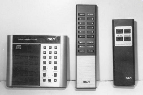
FIG. 1 Early remote transmitters used RF control until the infrared remote
was introduced.
Remote control functions
The infrared signal from a remote control device is picked up by a sensor in the unit to be controlled. The signal is picked up and applied to a system control integrated circuit (IC) that provides the various functions. Today, a TV remote can operate most of the features of both a TV chassis and a VCR. The DSS/TV/VCR remote can control the TV channels, up and down channels, single-channel button control, DSS cable, display, rewind, record, fast forward, menu processing, clear, picture in picture (PIP), move PIP, freeze PIP, skip, swap PIP, reset, antenna, volume up and down, and mute.
DSS remote control features may include power, set, TV, VCR, DVD, mute, up and down volume, channels up and down, exit, menu, quick, guide, WHO, audio, back, freeze, pushbuttons for each channel, OK, play, stop, record, pause, rewind, and fast forward for VCR operation.
A deluxe A/V receiver remote control may operate the TV, VCR, CD, tape, and receiver functions. Some of the buttons found on the face of the A/V remote control include on and off, TV, VCR, tuner, tape, CD, DVD, record skip, fast skip, play, reverse, TV channels up and down, volume up and down, independent TV channel buttons, tape deck, and muting controls.
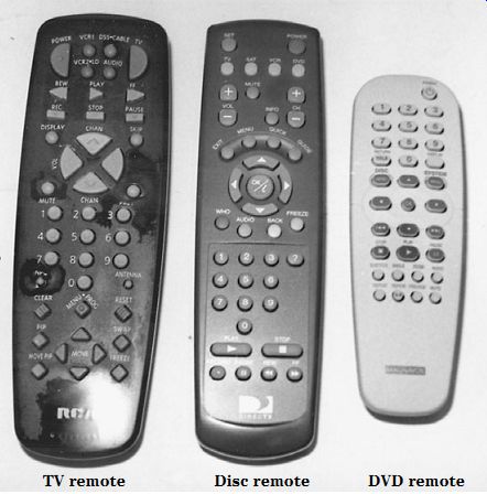
FIG. 2 A remote transmitter may operate a VCR, CD player, and DVD player
besides the TV. TV remote Disc remote DVD remote
RF remote control
The supersonic RF remote control transmitter sends out an RF signal that is collected by an RF indicator and sent to a system control processor. The RF control generates an electronic signal to control certain frequencies to be radiated through a speaker or transmitter. The frequency chosen was between 44.75 and 47 kHz. The frequency avoids most erroneous signals that might trigger the remote control receiver. Of course, garage door openers, door and telephone bells, and other super- sonic signals can trigger some TVs. Erroneous signals from various electrical and RF generating devices can trigger remote control receivers.
Infrared remotes
You must point an infrared remote transmitter directly at the unit to be controlled or no function will occur. If someone or something is in front of the infrared detector, the infrared signal will not trigger the infrared receiver. Nothing happens when a person walks in front of a TV as the remote is being used to select a station. The infrared remote will not trigger another remote electronic product found in a different room.
The infrared remote sends out an infrared signal from one or two transmitting light-emitting diodes (LEDs). This infrared signal is picked up by an infrared photo transistor sensor, amplified by transistors or one IC component, and fed to a system control IC. The system control may consist of a microprocessor, a central processing unit (CPU), or a system control IC in the latest TV circuits. The processor chip sends the remote control messages to the various circuits to be operated (Fig. 2). In the sound circuits of some remote-controlled receivers, a small motor also rotates the volume control up and down.
The dropped remote
One of the biggest difficulties when using a remote control is dropping the remote on a hard floor. Sometimes the remote becomes tangled up with newspapers and magazines and is dropped accidentally on the hard floor. You try to turn the TV or receiver on, and there is no operation. The dropped remote can come apart, or the batteries can pop out from the plastic case. Simply remove all the batteries and re install them with the correct polarity.
When these small batteries are installed backward, the remote will not function.
Check the positive and negative terminal signs inside the remote when installing new or dropped-case batteries. Make sure that the battery end terminals are not bent out of line. Take a small screwdriver or knife blade and bend the battery terminals toward the batteries to make a good contact. Sometimes if the remote is dropped on a cement floor, the PC board can be cracked or the wire traces can be broken.
Dead, no operation
A dead remote may be caused by defective, corroded, or weak batteries. Most remote control units operate with AAA or AA batteries. Two or more batteries (3 to 6 V and 9 V) are connected in series to power some remote control transmitters. Some units are operated with only two AA (1.5-V) batteries. The high-powered DSS control may operate with four AA (6-V) batteries. A remote transmitter will not function with dislodged batteries, improper polarity, bad end-contact strips, or weak batteries.
The remote transmitter may not operate the TV or receiver when it is left for a long time and not used. Remote transmitters left in a cold room may not control the TV the next time the on button is pressed, may become weak from many hours of operation, or may not work if the battery voltage falls to 1 V. Sometimes one battery becomes defective and causes the remote to malfunction. If the remote will only turn on the TV when it is within 2 or 3 ft of the TV, suspect weak batteries (Fig. 3).
Preferably, check the batteries with a battery tester. If one is not available, check each battery under load with the low-voltage range of a digital multimeter (DMM). Hold down one button, and test the voltage across each battery. Replace all batteries that test 1 V or less. Weak batteries can cause intermittent or weak operation. It is best to replace all batteries when one or more are found to be weak or dead. Always replace all the batteries at the same time. Replace remote control batteries with high-energy batteries.
Heavy-duty power cells or ultra-alkaline batteries have a relative service life of from 2 to 10 times longer than ordinary carbon batteries. Wipe the new battery contacts by rubbing against a cloth, towel, or pant leg before installing. Make sure that the positive (+) terminal is inserted properly. Most battery holders have marked positive and negative terminals. Double-check the battery polarity.
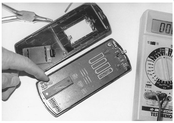
FIG. 3 Suspect weak batteries when remote operation is intermittent or the
remote must be close to the electronic product to function.
Aim at the target
You must aim the remote transmitter directly at the receiver's infrared indicator or the electronic product will not operate. Aim the remote high above any object that might be in front of you and the electronic product to be operated. The infrared re mote operates silently, and the only indication that the remote is working is when the light appears on the remote transmitter. Bring the remote close to the TV to see if it will function. Check for weak or dislodged batteries if the remote fails to turn on the TV. Suspect weak batteries when the remote will only operate a few feet from the TV and will not function while you are sitting in an easy chair.
A quick method to determine if the remote is not functioning or the infrared indictor within the electronic product is defective is to push each button of the remote next to a battery-operated portable radio. Each time a button is pressed, you can hear a gurgling sound in the portable radio. If a button produces an erratic gurgling noise, this particular button assembly is dirty and not making a good contact. However, this test does not indicate the strength of the remote infrared signal.
Another method is to use an infrared indicator card in front of the remote transmit ter. The infrared card will change to a different color if the transmitter is working. These indicator cards can be obtained through TV and parts distributors. The RCA infrared indicator card for checking the output of remote control transmitters is stock number 153093. Such infrared cards will only indicate if the infrared signal is present but not how strong or weak the signal is. They only indicate that the remote control is operating.
Try another one
Simply try another remote to see if it will turn on the TV set, VCR, CD player, or DVD player. Usually, there are several different remotes in the house. Most remotes will have a function that will operate another receiver in the TV or VCR. If the subbed re mote operates one or two functions, you can assume that the sensor and receiver are operating. Then check the defective remote transmitter.
Tap that remote
Just tapping the remote may make it work, indicating weak batteries, poor battery contacts, or batteries that are not seated properly. An intermittent remote can irritate most anyone. Remove the battery cover and test each battery on the battery tester or under load with the voltage tester of a digital multimeter (DMM). Clean the battery tab contacts. Make sure that these contacts are not corroded. Sometimes, if a battery begins to leak, it can corrode the metal battery connection. Sandpaper or a finger nail strip can easily clean a damaged battery clip.
Loose components or cracked printed circuit (PC) boards can cause a remote to operate intermittently. Inspect the PC boards under a strong light. Check all the coils, transistors, and capacitors for loose or broken leads. Resolder all connections on the PC board. Make sure that the wires to the battery terminals are intact and soldered. When large defective components are found inside a remote transmitter, send it in for repair, or if it is under warranty, exchange it at the manufacturer's warranty or tuner depot. Re place the remote if the unit is out of warranty because you can find them everywhere at a very low price.
Infrared power meter
The infrared power meter that is used to check the laser optical assembly in a CD player also can be used to test out infrared remote control transmitters. Start with the lowest scale of the power meter (0 to 0.3 mW). If the results are poor, move up to the next scale. The laser power meter may have a 0.3-, 1-, or 3-mW range with switchable wavelength settings of 633 and 750 to 820 nm. A laser power meter that can be used in such infrared tests is a Tenma number 72-670 (Fig. 4). In addition, a Leader laser power meter number 70-510 can be ordered by mail from MCM Electronics, 650 Congress Park Drive, Centerville, OH 45459-4072.
FIG. 4 A laser power meter can quickly test a remote transmitter.
Place the probe 3 in from the pickup probe, and register the measurement on the power meter. Likewise, check the power of the remote control unit, and write down the measurement. By making comparison tests with new remotes, defective or weak remotes can be discovered. Move the remote back and forth to acquire the best reading. A weak or a dead remote will have a low or no measurement compared with a normal remote. Then adjust the batteries and contact terminals to obtain a higher measurement. Remote comparison tests with the laser power meter can indicate if the remote or receiver is defective.
Weak reception
Weak, intermittent, or erratic remote control operation results from weak batteries, bad battery terminals, and dislodged batteries. Try the remote out as you approach the TV or receiver to determine the distance at which the remote operates. Replace weak batteries when some of the functions of the remote will perform only extremely close to the electronic product. Inspect the end terminals where the batteries make contact. Clean the contacts with cleaning fluid. Try another remote to determine if the remote in question is defective or the problem is in the infrared indicator in the receiver.
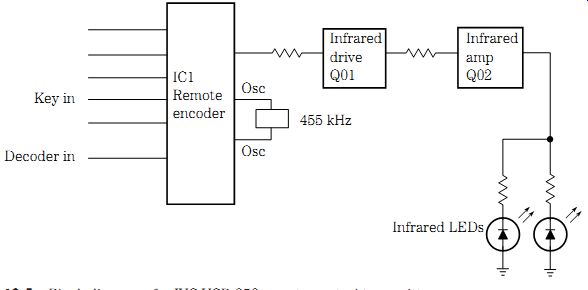
FIG. 5 Block diagram of a JVC VCR-258 remote control transmitter.
Infrared remote circuits
The infrared remote transmitter may operate with one or two infrared LEDs in the output. These LEDs are usually driven by one or two transistors in a series operation. The driver transistor has a code output terminal from the remote encoder IC.
Several different pushbuttons provide key in, decoder in, and scan out terminal connections from the encoder IC. Two AA or AAA batteries provide voltage to the re mote transmitter circuits.
In a JVC VCR-225 VCR, the remote encoder IC1 drives an NPN and a PNP transistor in a series circuit with two infrared LEDs at the output. The first transistor (Q01) acts as a infrared driver, and the second transistor (Q02) acts as a infrared amp output.
Both infrared LEDs are fed in a parallel output circuit from collector Q02. The key in pin terminals of the remote decoder IC1 are fed from fast-forward, rewind, power, play, pause/still, stop, TV/video, channel next, and channel back switch keys. The record (REC) button is tied to decoder in terminals 9 and 10.
A 455-kHz oscillator network provides oscillator action on pins 2 and 3 of IC1. The infrared code input is taken from pin 17 to the base of Q01 with a low-ohm resistor tied in series with the collector of Q01 to the base terminal of Q02. The two infrared LEDs are tied to the collector terminals of infrared amp Q02. Two AA 1.5-V batteries power the remote control transmitter (Fig. 5).
In a Panasonic PV-M2021 TV/VCR, the remote transmitter has only one emitting infrared LED, an infrared driver transistor (Q6801), and a multifunction remote control IC6801. A crystal oscillator is found on pin terminals 20 and 21. The key in circuits from the different pushbuttons tie into pins 3 through 10. The scan-key circuits are tied to pins 12 through 18, whereas pin 19 goes to the base terminal of Q6801. A 3-V battery dc source powers the remote transmitter (Fig. 6).
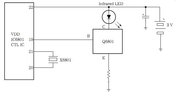
FIG. 6 The infrared wireless remote transmitter block diagram found with
a Panasonic PV-M2021 TV/VCR.
Remote control problems
One of the biggest problems with remote controls is dropping the remote on a hard surface and dislodging the batteries. A weak battery can cause intermittent or no operation of the remote transmitter. Oozing batteries can corrode the battery contacts.
Dirty or poor battery contacts can cause no or intermittent operation of the remote.
Replace the batteries when the remote will work one time and not the next. If the re mote control will only operate up close to the TV, replace the weak batteries. Reseat the batteries when the plastic battery lid will not close properly.
If the batteries are replaced and the remote still does not function, remove the top or bottom cover. A stiff knife blade between the two lids can pop open the plastic case. Check each transistor with the transistor tester or the diode tester of a DMM. Test the infrared diode as you would any silicon diode. The infrared diode can be checked on the diode tester of a DMM with a higher reading than a normal silicon diode. Each pushbutton can be tested with low-ohm resistance tests on a DMM. Clip the DMM leads across the pushbutton terminals, and press the button down for a shorted measurement. Replacing the large encoder IC, however, may cost as much as a new remote. Generally, it is easier to replace the remote with a new one because replacements are fairly cheap and can be purchased anywhere (Fig. 7).
More than one
A remote control transmitter can operate most TVs, VCRs, CD players, DVD players, and deluxe receivers. The General Electric RRC500 does the work of three remotes, whereas model RRC600 does the work of four remotes. RRC600 controls up to four infrared audio/video products, with over 200 key combinations, program sequencing, LCD display, and a low-battery indicator.
This remote, like all other universal remote control units, can be programmed to work on virtually all electronic products. These remote control units can be purchased at TV dealers, hardware stores, mall stores, and Radio Shack (Fig. 8). The universal remote operates on batteries and can be checked with the infrared tester like other re motes. The RCA DSS receiver can be operated with some universal remote control transmitters (e.g., Radio Shack 15-2116).
FIG. 7 Quickly check the infrared LED with the diode tester of a DMM.
FIG. 8 Inside view of a remote control with separate buttons for the TV and
VCR/CD player.
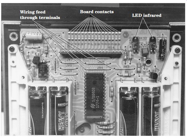
FIG. 9 The infrared IC, transistor, and LEDs found in a dual remote control
transmitter.
Inside the remote
The plastic top or bottom plate of a remote control can be removed by inserting a screwdriver or knife blade in the broken seam. The top and bottom plastic case parts are held together by plastic clips on each side and at the ends. Remove the battery cover or lid and batteries before trying to open the plastic case. Very few components are found on the inside of a remote control (Fig. 9).
If the PC board is cracked and cannot be repaired, replace the remote control.
Check the emitter LED with the diode tester of a DMM; it should read about twice the resistance of a silicon diode in only one direction. Likewise, the LED light can be checked in the same manner. Check the transistors with the diode tester of a DMM. Of ten the pushbutton terminals are found in the PC wiring side of the remote.
Remote receiver problems
When the remote has been tested or subbed with another unit and the electronic product still does not respond, the trouble can be in the infrared receiver or standby power supply circuits. In today's TV receivers, the standby voltage is on all the time, even when the TV is turned off. The remote receiver must be alive to receive the commands of the remote control to turn the electronic product on.
The remote control receiver sensor is found in the front panel of any electronic product. This infrared sensor is actually an infrared phototransistor that picks up the infrared signal and connects it to the remote receiver in the TV, VCR, or CD player. The infrared sensor is usually placed in a shielded container to prevent outside noise and unwanted signals from striking it.
In earlier infrared receivers, small transistors were used to amplify the weak signal to the system control IC. You may now find an IC component between the infrared sensor and the decoder. One large IC may be found with a transistor amp before feeding the remote signal to the system control IC. In turn, the system control IC operates the various functions of the remote transmitter.
TV RECEIVER REMOTE CIRCUITS
The TV remote circuits consist of an infrared detector, a remote receiver, a driver transistor, and a system control IC or microprocessor. The standby power supply must be on all the time to provide voltage to the infrared receiver and system control circuits. The infrared detector picks up the remote transmitter's signal, which is amplified and decoded within the IC receiver circuits. Sometimes the infrared detector or phototransistor and IC provide signal directly to the IC microprocessor or system control IC. This infrared signal may go through several different connectors and boards before it is applied to the system control IC.
JVC INFRARED IC RECEIVER
In early infrared IC receivers, the infrared LED detector signal was amplified by several transistors. Today, the infrared detector has an IC component in the receiver circuits. The infrared receiver (IC1) receives the infrared signal from the detector, and the output is fed to an operational board or to the control IC in a JVC VCR-255 VCR.
The infrared IC1 receiver signal is fed to an operation and monitor board and then on to the mechanical control IC601. IC1 is powered by a regulated 12-V standby voltage source. A standby voltage source is on all the time as long as the TV is plugged into an ac receptacle (Fig. 10).
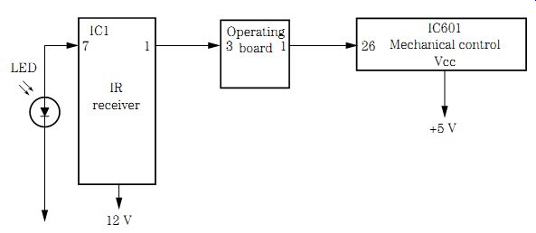
FIG. 10 Block diagram of a JVC VCR-255 infrared receiver.
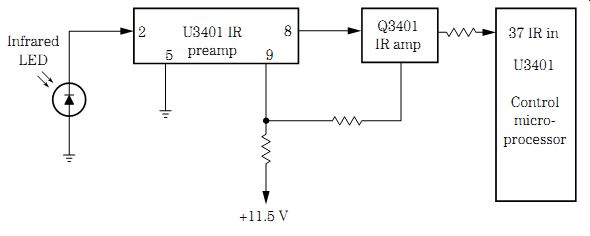
FIG. 11 Block diagram of an RCA CTC167 infrared receiver and remote circuits.
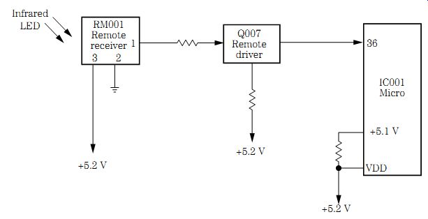
FIG. 12 Block diagram of the infrared receiver in a Panasonic CT-27S18S/CS
TV.
RCA CTC167 INFRARED RECEIVER
The infrared preamp IC (U3401) is found in the tuner control schematic with CR3401 as the LED detector that feeds into pin 2 of U3401 of an RCA CTC167 chassis. The output signal at pin 8 feeds to an infrared amp transistor (Q3401) and to input terminal 37 of the control microprocessor (U3401). The infrared receiver IC is powered by an 11.5-V source from the secondary voltage of the flyback (T4401). A standby voltage source feeds a 12- and 5-V source to power control microprocessor U3101. U3101 provides the remote signal to the various control functions of the TV (Fig. 11).
PANASONIC REMOTE RECEIVER
The infrared remote receiver signal is picked up in a Panasonic CT-27S18S/CS TV by the infrared remote receiver (RM001) and fed to a remote switch transistor (Q007). The NPN remote switch transistor feeds the infrared signal from the collector terminal to the remote receiver at pin terminal 36 of the microprocessor (IC001). The RM001 remote receiver is powered from a 5.2-V source to most terminals on the microprocessor IC001.
The 5.2-V source is fed from a separate standby transformer source. The manual control button functions are found on the terminals of the microprocessor (IC001) (Fig. 12).
Troubleshooting the TV infrared receiver circuits
To determine if the infrared remote or the electronic product receiving circuits are defective, try another remote. Usually there is more than one in the house. If neither remote control operates the TV, VCR, CD player, or DVD player, suspect a defective component inside the infrared receiving unit. Notice if the TV works with the manual controls but not with the remote. Locate the infrared sensor, and trace it to the preamp IC. Some infrared receivers have a scope test point at the output of the infrared IC. Check the supply voltage on one pin terminal of the infrared IC. Usually the supply voltage is either 5 or 12 V dc. Go directly to the standby power supply if very low or no supply voltage is measured at the infrared IC and driver transistor.
Sometimes loose or broken cable connections produce intermittent remote control functions in the receiver circuits. Scope the remote signal, and take accurate voltage and resistance measurements on the IC and transistor components to locate the defective component. Test diodes and transistors in the receiving circuits with the diode tester of a DMM. Check for a badly soldered joint on the infrared sensor where it connects to the PC board when there is intermittent remote operation in a Magnavox 19PRC-0121 TV.
NO RECEIVER ACTION, RCA CTC167
Although manual control operated all functions in an RCA TV, remote operations were dead. However, the same remote control operated the VCR player. This meant that the trouble had to be in the infrared preamp section of the receiver. The defective component had to be in the infrared preamp IC (U3401). A quick voltage measurement on terminal pins of the infrared IC (U3401) showed practically nothing (0.57 V).
At first, the standby power supply was suspected of providing no or very little supply voltage to pin 9 of the infrared preamp IC. CR3402 and CR3401 checked normal with the diode tester of a DMM. A low resistance measurement was found from pin 9 to ground. After removing pin 9 from the PC wiring with solder wick and an iron, the 5.1 V supply source showed up. The infrared preamp (U3401) was replaced because a leak age test indicated that the IC was causing the low supply voltage source (Fig. 13).
NO INFRARED RECEIVER RESPONSE, GE CTC146
Although the manual buttons on the front of the TV worked, no remote functions occurred with the infrared remote in a GE CTC146 TV. A quick voltage test was quite normal. A continuity test from the infrared circuits to pin 8 of U3401 showed an open circuit. Resoldering the trace PC wiring restored the remote control functions at pin 8 of U3401 (Fig. 14).
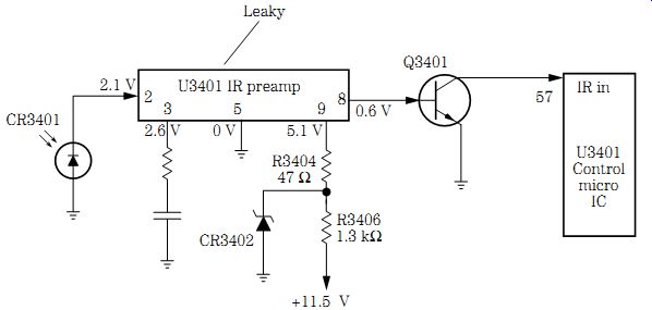
FIG. 13 A leaky preamp IC (U3401) reduced the 5.1-V source to 0.15 V in an
RCA CTC167 infrared remote receiver.
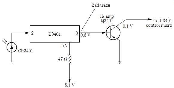
FIG. 14 A badly soldered joint at pin 8 of U3401 caused no remote functions
in a GE CTC146 TV.
Infrared receiver case histories
A leaky channel up switch caused the channels to scan continuously with reception only on channels 3, 4, and 83 with no remote action in an Orion TV1928 TV. No re- mote control action in a Panasonic CTZ-2042R TV was caused by a bad M004 remote receiver (part number EUR37234). The defective IC003 remote receiver in a Panasonic CT-27G24A TV produced no remote control action. A corroded resistor R139 (100 ohms, 1/8 W) located at the front of an Emerson TC1966D TV caused the remote not to function. The auto programming would not lock in on cable channels 7 to 13, 16 to 18, and 19 to 37, and when the remote was used, the picture would tear horizontally as a result of a bad electrolytic C052 (100 uF, 16 V) in a KTV-19TEC TV.
In an Admiral JSJ-12674 TV, channel 8 would not change and there was no remote action as a result of a bad EEPROM memory chip (IC2701). Replace the MM001 remote receiver when there are no remote functions in a Panasonic CT-27G31U TV. Check and replace the microprocessor (IC2001) in a Sharp 25G-M100 TV when the remote will not operate. A badly soldered joint on pin 5 (ground) of connector J4 of the ribbon cable from the infrared receiver to the main board in a Magnavox 25G1-03 TV caused intermittent loss of remote control action. Replace the IC (CX20160K) in the remote receiver for no remote operation in a Sony KV-13TR24 TV. No remote functions occurred in a Zenith SS1915N8 TV as a result of a badly soldered joint connection from the infrared receiver where it joins the main PC board.
RCA CTC145 REMOTE RECEIVER
In this TV chassis, the remote sensor is fed into a transistor infrared amp and a second, third, and fourth infrared amp in series. All the infrared amp transistors and sensors are enclosed in a shielded area. The top shield cover must be in place before the remote will function (Fig. 15). A +12-V source is fed to the infrared receiver and analog microprocessor (U3300).
When the infrared receiver does not function, check the dc voltage ( _12 V) to the infrared stages. Test the infrared detector (CR3404) with the diode tester of a DMM. Take an in-circuit transistor test of each transistor. A scope test at the fourth infrared amp output or pin 36 of U3300 should indicate whether the remote receiver is functioning. The infrared test point is found at FB3304 and FB3305. Suspect IC U3300 if the infrared receiver is functioning but there is no remote control. Check for a standby +5 V on the microprocessor.
FIG. 15 In the early RCA CTC145 TV remote receiver, transistors Q3401 through Q3404 amplified the infrared signal to the system control IC (U3301).
TV standby circuits
The standby circuits in the low-voltage power supply provide an operating voltage source to the infrared receiver and system control or microprocessor circuits. The standby power supply might have a separate low-voltage power transformer regulated supply in some TV circuits. The latest standby power supplies are taken off the secondary winding of the switching transformer. The standby power supply provides a 5- or 12-V source to the infrared receiver circuits.
A simple low-voltage power transformer supply may consist of a low-voltage power transformer, a half-wave silicon diode, filter capacitors, and a zener diode or transistor regulated circuit. The power transformer is connected after the main ac fuse and is connected directly to the primary winding (120 V ac) of the power transformer. The secondary winding of the standby power transformer is connected to a single silicon diode and common ground terminal. Several resistors, diodes, and electrolytic capacitors are found in the 5.2-V standby source. No remote action in a Sylvania 20B1-03 TV was caused by a defective C2 capacitor (3.3 uF, 50 V) inside the remote control receiver.
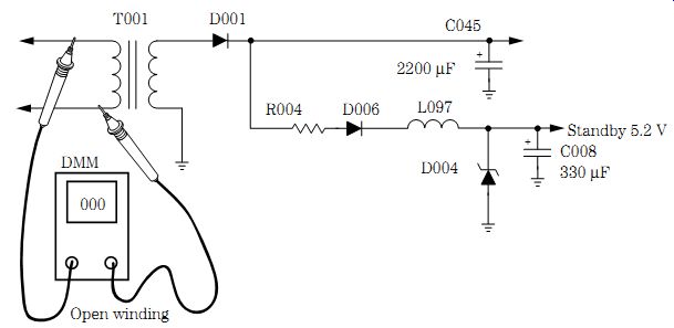
FIG. 16 An open primary winding of the power transformer (T001) caused no
5.2-V standby voltage in a Panasonic CT-31S18S/CS TV.
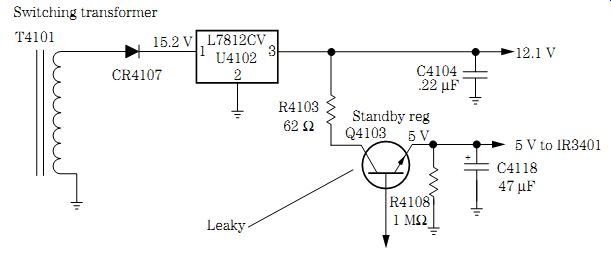
FIG. 17 A leaky regulator (Q4103) caused low standby voltage (5 V) to the
IR3401 remote receiver.
Dead remote operation
A Panasonic CT-31S18S/CS TV would not turn on with the remote control. The re mote transmitter operated the VCR but not the TV. This meant that the trouble had to lie in the infrared receiver circuits. The remote receiver was located at the front of the TV chassis, and no supply voltage was found at pin 3 of the system control IC.
Since most remote infrared receivers feed into a system control IC or microprocessor, the voltage source was traced back to the standby power supply.
A separate power transformer (T001) was found on the TV chassis with D001 rectifying the standby voltage. No standby voltage source was noted at the collector terminal of D001 or at the positive terminal of the main filter capacitor C045 (2200 uF). Since the secondary voltage of most low-voltage power supplies is wound with heavier copper wire than the primary winding, a quick continuity check of the primary winding was taken.
The primary winding should have a resistance of around 500 to 850 ohms, and the winding was open. Usually, power transformers are damaged by shorted silicon diodes or electrolytic capacitors. D001, D002, D003, D004, and D006 were normal on the diode tester of a DMM. Replacing T001 resolved the dead remote power source. These small low voltage transformers can be found at most electronic outlets or Radio Shack (Fig. 16).
Switching transformers
In the latest infrared remote power circuits, the standby power supply is taken from a switching transformer winding. The switching transformer is alive all the time the TV is plugged into an ac outlet. A silicon diode, transistor, and IC voltage regulators are found in a regulated standby power source. You may find a 5- or 12-V source feeding the infrared remote receiver and system control IC so that the remote transmitter can trigger the remote control system (Fig. 17). The power switch (SW2501) was found to be open in a Sharp 25J-M100 TV, and this resulted in no remote control action.
Intermittent standby voltage
The infrared remote receiver in an RCA CTC166 TV consisted of only the IR4301 re mote receiver module that picks up the infrared signal and feeds it into pin 1 of the system control microprocessor (U3101). The 5-V standby power source is fed from a +5-V standby regulator (Q4103), which receives a 12-V input voltage from the 12-V standby regulator IC (U4102).
The 15.2-V source that feeds U4102 comes from the secondary winding trans former T4101. CR4101 rectifies the dc voltage applied to IC (U4102) and the 5-V source from a +5-V standby regulator transistor (Q4103). The same +5-V source feeds most system control functions of U3101.
The intermittent +5-V source was traced to the low-voltage power source. The 5-V source appeared erratic or intermittent when the DMM was used to monitor it at the emitter terminal of Q4103. Sometimes the voltage was okay for a few hours, and at other times the TV could only be operated by the pushbutton on/off switch, volume up and volume down, and channel up and down functions. The 12-V source feeding the collector of Q4103 was normal at all times. Q4103 was replaced with part number 223704, and this resolved the intermittent remote control operation (Fig. 18).
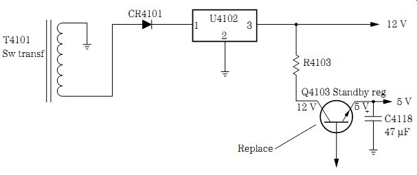
FIG. 18 Replace Q4103 for intermittent +5-V standby voltage in an RCA CTC166
TV.
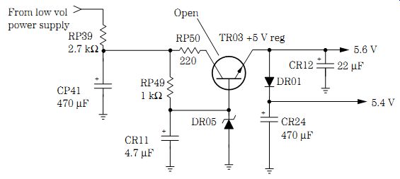
FIG. 19 An open regulator transistor (TR03) in the 5.6-V source caused no
standby voltage to the preamp IC (IR02) in an RCA TX82N TV.
Open 5-V regulator, no remote function
In an RCA TX82N TV, the remote would not operate the remote control functions, but the front panel controls were okay. Another remote was tried with the same result. This indicated that the defective component had to be in the infrared receiver or standby power supply. A quick voltage measurement on preamp IR02 indicated very little supply voltage. The standby voltage source was traced to the low-voltage power supply circuits. A quick method to locate the voltage supply source is to take an ohmmeter measurement from the supply pin of IR02 to the low-voltage circuits.
The 5-V source was traced back to CR24 (470 uF) and DR01. No voltage was measured on DR01 or on the emitter terminal of the 5-V standby regulator transistor (TR03).
A dc voltage was found on the collector and base terminals of TR03. Both DR05 and DR01 were checked with the diode tester of a DMM. TR03 was checked in the circuit with the diode tester of a DMM, and the emitter terminal appeared open. TR03 was replaced with a universal NTE123AP transistor, and this resolved the missing 5-V power source to the remote control receiver circuits (Fig. 19). Also, defective TR03 and DR05 can cause intermittent startup and shutdown symptoms in this same RCA chassis.
Servicing standby power circuits
When low or no dc voltage is found at the IC or transistor preamp within the infrared receiver, go directly to the standby voltage source. Carefully look over the TV chassis or electronic product for a small power transformer that supplies ac voltage to the standby power circuits. Determine if the standby voltage is fed to a low-voltage regulator source from a switching power transformer in switching power supply circuits if no single low-voltage transformer is found on the TV chassis. You may find that the standby power source is in the switching power supply of many of the latest TV chassis. If in doubt, check a similar TV chassis or a schematic from the same manufacturer.
Quickly check the dc low voltage on each diode in the secondary of the switching transformer circuits for no or a low-voltage source. Next, check the dc voltage on each IC or transistor regulator for a 12- or 5-V source. The standby output voltage will be at the emitter terminal of the transistor regulator. Another method is to check the voltage on each electrolytic capacitor in the secondary voltage sources. The regulator that has no or very low voltage can be the suspected power source.
Now trace the missing voltage source to a diode, transistor, or IC voltage regulator.
Check each transistor in the low-voltage sources with the diode tester of a DMM. Check the dc voltage on the collector and base terminals of the suspected transistor regulator.
The dc voltage may be a little higher on the base and collector terminals when there is a defective transistor regulator. A shorted transistor regulator may have very low voltage on all three terminals.
The input terminal of an IC voltage regulator will be high with no or low voltage out of the output terminal when there is an open regulator transistor. A leaky IC regulator may have low voltage on the input terminal and very little voltage on the output terminal (Fig. 20). Since the IC regulator has only three terminals and one terminal is grounded, low input and output voltage can indicate a defective IC regulator.
Intermittent remote operation
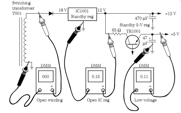
FIG. 20 Check the various circuits within the standby voltage circuits with
a DMM.
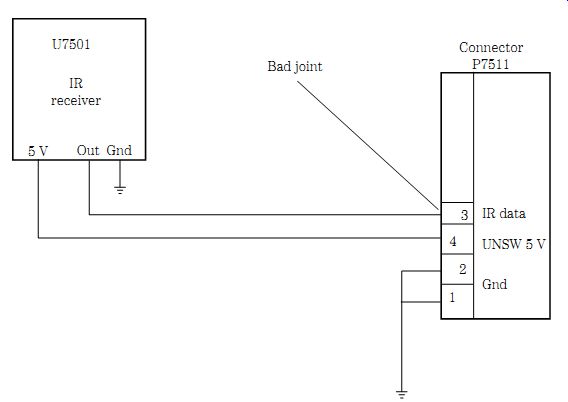
FIG. 21 Intermittent remote action as a result of a poorly soldered joint
at pin 3 of the connector (P7551) in a Panasonic PV-M2021 TV/VCR.
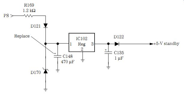
FIG. 22 Sometimes no channel up or channel down operation was caused by electrolytic
C148 (470 uF) in an Emerson TC1965D TV.
Sometimes the remote function would operate and at other times not in a Panasonic PV-M2021 TV/VCR. Trying another remote control transmitter did not help. A quick voltage measurement (+5 V) on the infrared sensor (U7501) was normal for several hours. When the wiring connector P7551 was touched, the re mote system appeared normal and then went into the intermittent mode. The connecting wire to pin 3 was re-soldered, and the remote began to function. The badly soldered connection at P7551 was the cause of the intermittent remote operation (Fig. 21).
No channel up and down
The manual up and down buttons operated okay, but the remote control would not function in an Emerson TC1965D TV. The remote transmitter seemed okay. Some times the remote up and down would function and at other times not. The 5-V standby source was taken off the external power supply and fed to the remote receiver circuits. The TV remote would operate for a whole day every time it was used.
Sometimes the +5-V source appeared low and at other times normal. The input voltage on pin 1 would vary on the remote IC. IC102 was suspected but tested okay.
Since a bad electrolytic filter can cause low voltage in a power supply source, C148 was checked with an equivalent series resistance (ESR) meter. When C148 was shunted with another 470-uF electrolytic, the remote worked for days. Replacing the C148 (470-uF) electrolytic filter capacitor resolved the no channel up and down symptom (Fig. 22).
No remote receiver action
The remote control would not turn on a Sharp 19SB60R portable TV. The remote was tested and seemed normal. Very little voltage was found on receiver terminal pin 2. A voltage test was made on the +5-V standby voltage and was fairly normal. Resistor R1016 (100 ohms) appeared quite warm (Fig. 23). A low resistance measurement was made at pin 2, and the receiver shielded area showed only 27 ohms to ground.
Pin 2 was removed from the remote receiver, and the voltage was still low. On checking the wiring, a zener diode appeared burned and quite warm. Replacing leaky diode D1052 solved the problem.
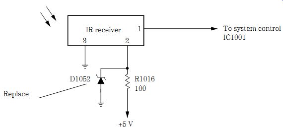
FIG. 23 Leaky D1052 in a Sharp 19SB60R portable TV resulted in a dead remote
control receiver.
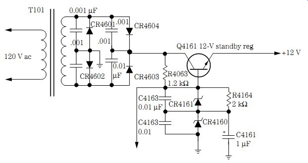
FIG. 24 Replace both CR4161 and CR4160 in the standby circuits when the remote
will not function in a dead RCA CTC157 TV.
No remote, dead TV
A dead RCA CTC157 TV receiver with no remote operation was brought in. Because the picture tube had a blank raster and there was no remote action, the symptoms were traced to the low-voltage standby circuits. The 12-V voltage source was found in the standby regulator power supply circuits.
The standby transformer was located on the chassis, and the ac voltage was measured to the bridge rectifier circuits. A reading of 24.7 V was found on the collector terminal of the 12-V standby regulator (Q4161). Very low voltage was found at the emitter terminal (Fig. 24). Q4161 tested good with an in-circuit transistor test. CR4161 and CR4160 were found to be leaky and were replaced. The 12-V standby voltage was now measured on the emitter terminal of Q4161 regulator. CR4161 and CR4160 were re placed with universal ECG5071A zener diodes.
Check Table 1 on p. 410 for troubleshooting remote controls, infrared receivers, and standby circuits.
Table 1. Remote control troubleshooting.
=============
[Symptom:
Dead remote control
Intermittent remote operation
Weak reception
Remote normal-no action
Standby power supply problems ]
[Repair:
Check and test the batteries. Check the remote against the indicator card. Test the remote with a laser power meter. Sub another remote.
Clean the battery terminals. Check for loose batteries. Remove the batteries, and clean the end terminals with sandpaper. Bend the terminals out for a tight fit. Suspect the remote has been dropped several times. Inspect the PC board for cracks or loose parts.
Check batteries-replace all the batteries when one is found bad.
Test the remote on an indicator or power meter.
Check the voltage source to the IC or transistor amps. Take waveform tests. Test each transistor in the circuit. Take voltage tests on the IC amp or receiver. Test the sensor unit with a diode test of the DMM.
Suspect the standby voltage supply.
Check the output voltage supplied to the IR receiver. Test the output voltage on the standby supply. When low or no voltage is found at the IR regulators, test the transistors and zener diode regulators with a diode test of the DMM. Remember the standby voltage must be present or the remote won't work.]
============