A DVD player may appear in a separate cabinet, by itself, or with other electronic products. A DVD/CD player combination provides digital video and audio music on separate discs. You can enjoy a stunning picture with a DVD and play your favorite music on a CD. Some DVD players can play DVD video, MP3s, CD-Rs, and CDR-Ws. A DVD/CD combo player can be found in home theater systems and even in boom-box players (Fig. 1).
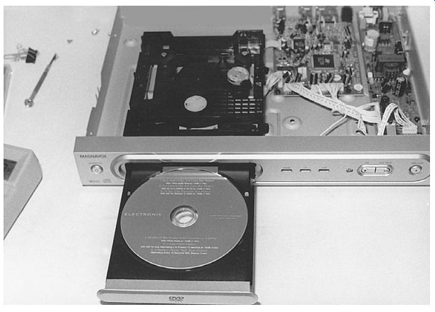
FIG. 1 Loading a DVD in a DVD/CD player.
A DVD/CD/VCR combination player can provide digital video in the TV chassis or VCR and your favorite music with a CD player. Some of these DVD players also can play back your MP3s. A DVD/CD/VCR combo player may appear in a single cabinet or within a TV set. You can record your own discs on the DVD/VCR recorder.
DVD/CD RW combo drive units appear in portable 2004 notebooks. Portable DVD notebooks can play a DVD, a CD-R/RW, a video CD, or an MP3 on a 5-in or 6.8-in liquid crystal display (LCD) screen. An in-dash or overhead DVD/CD player is now produced for mobile video viewing within an automobile. You can play many hours of recordings on a DVD/CD three- or five-disc changer.
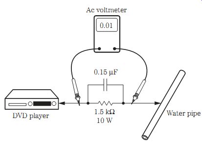
FIG. 2 Check the ac voltage across a 1.5-kilohm resistor for a hot current
leakage test.
CD and DVD comparison
The CD provides a method of storage for video, audio, or computer data. The original CD provided high-fidelity music with a typical capacity of 650 MB, whereas the DVD offers a minimum 4.7 GB by having a shorter laser wavelength, greater pit density, narrow track spacing, faster rotation speeds, and faster servo systems.
The DVD laser can produce a shorter-wavelength beam that is measured in nanometers. A shorter wavelength provides greater precision in operation. Two different data layers provide accurate focusing systems. The second DVD layer must have a laser beam that focuses deeper. The laser beam in a DVD player must be stronger so as to read both the first and second layers. As in a CD player, the laser beam strikes the bottom side of the disc, opposite the label side, which is mounted upward.
Safety precautions
Before a DVD player is returned to the customer, make cold and hot leakage tests.
Simply connect a jumper wire between the unplugged ac two-prong plug of the ac cord. For a cold leakage tests, take the resistance measurement between the jumped ac plug and the outside of the metal cabinet, screw-head connectors, control shafts, and exposed metal parts. The ohmmeter measurement should be somewhere between 1 and 5 megohms.
For a hot leakage test, plug the DVD player into an ac outlet. Connect a 1.5-kilohm, 10-W resistor in parallel with a 0.15-uF capacitor between an exposed metal part of the DVD player and a good ground (Fig. 2). Measure the ac voltage across the resistor and capacitor. The ac voltage should not be over 0.75 V root mean squared (RMS). Check for possible shock hazard in the DVD player if the ac voltage reading is higher. Recheck and repair the equipment before it is returned for easy viewing and high-fidelity listening.
Electronically sensitive devices
Some semiconductors can be damaged by electricity or continuous handling of electronically sensitive (ES) devices. Integrated circuits (ICs), field-effect transistors, and semiconductor chip components can be damaged by electrostatic discharge (ESD). Always wear an ESD wrist band or strap to drain off electrostatic charges from your body. Do not place ES devices on a conductive surface such as metal or foil. Make sure that optical assembly is grounded at all times.
Use only an antistatic soldering iron, or ground the metal point of the soldering iron. Use only an antistatic solder removal device. Do not use Freon or chemicals that can generate electric charges that can damage ES devices. Remove the replacement ES device only when it is ready to be mounted. Remove the electrical leads before mounting. Touch the unit to the chassis in which the ES device is installed. Make sure that no power is applied to the DVD player when installing ES devices.
Optical pickup
As in a CD player, the optical pickup assembly in a DVD player consists of a laser, a mirror, and a photo diode required to receive the information stored on the DVD/CD and change it into electrical energy. The spindle or disc motor rotates the disc while the DVD and CD data are picked up by the optical laser assembly. The objective lens focuses the beam onto the disc and collects the reflected light. The reflected light directs the laser beam toward a photodetector.
The optical mechanical assembly consists of the spindle or turntable motor, the SLED motor, focus and tracking coils, the clamper, and the servo control. The loading motor pushes out a loading drawer or tray and takes it back into the spindle motor to be loaded.
A clamper device holds the disc in position on the spindle or disc platform (Fig. 3).
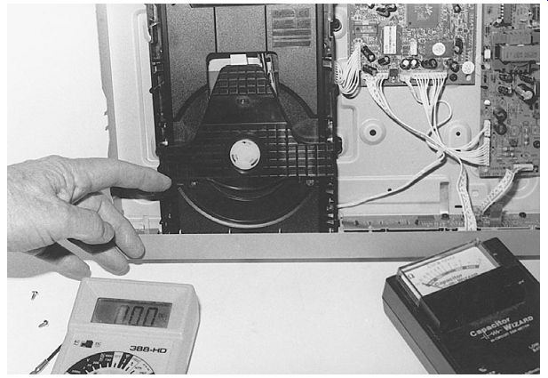
FIG. 3 The laser pickup assembly found within a DVD/CD player.
Do not take a peek
Remember, an invisible laser radiation is emitted from the optical assembly. You can not see the laser light. Do not look directly at the pickup lens assembly. You can dam age your eyes if you stare at the bare optical lens assembly while the player is operating. Usually a laser beam warning is found attached to the side of the optical as sembly. Always keep a disc loaded on the spindle when you are servicing a DVD/CD player. Remember, the laser beam is not visible like that of a light-emitting diode (LED) or pilot light.
Electrostatic grounding
The laser diode of the optical lens assembly can be damaged by static electricity built up on your clothes or your body. Make sure that your body is grounded with a anti static wrist strap. Place a conductive material on the work bench where the DVD/CD player is placed, and the conductive sheet should be grounded. Do not let your clothes touch the traverse or optical assembly when installing a new optical pickup assembly. Be sure to remove the shorting clip from the flexible ribbon connecting the optical unit to the DVD/CD player after installation.
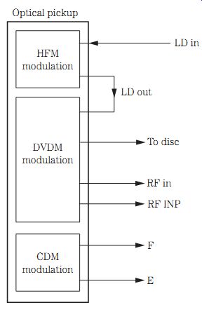
FIG. 4 Block diagram of an optical pickup assembly in a DVD/CD player with
LDM, DVDM, and CDM modulation.
Block diagram of a DVD/CD optical assembly
The optical pickup assembly of a DVD/CD player may consist of a high-frequency modulator (HFM), a DVD modulator (DVDM), and a CD modulator (CDM). The linear drive (LD) switch is found between the front-end processor and LD in of the high-frequency modulator. The LD out of the high-frequency modulator is fed to the LD in of the DVD modulator. The SW signal is fed to the DVD modulator and onto a disc servo control (DSC) processor (IC2001).
The tracking and focus signals from the DVD modulator are fed to the front-end sensor (IC5201). RFN and RFP are also fed to IC5201. A CD supply switch is fed into the LD terminals of the CD modulator. The focus, error, and monitor signals are also fed into the front-end processor (Fig. 4).
The HFM optical pickup assembly consists of an IC module and surface-mounted components. The DVDM optical assembly contains many optical integrated circuits (ICs), transistors, and diode components. The CDM assembly may consist of several optical ICs, diodes, and transistors within the CDM block of the optical pickup unit.
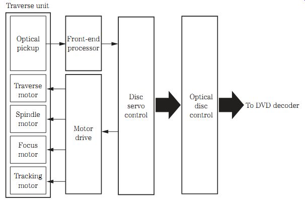
FIG. 5 Block diagram of the traverse unit found in a Panasonic DVD/CD/VCR
player.
Block diagram of a DVD/CD/VCR optical assembly
The DVD traverse unit in a DVD/CD/VCR player may consist of an optical pickup assembly that is fed into a front-end processor (FEP), and the output of the FEP is fed to a DSC processor. The traverse motor is fed from a motor driver IC that is con trolled by the DSC processor. Likewise, the spindle motor, focus motor, and tracking motor are controlled by the motor drive IC with signal from the DSC processor.
The DSC IC signal is fed to the optical disc control processor and then fed to the decoder IC (Fig. 5).
Always use a variable-voltage isolation transformer when servicing a DVD/CD/VCR chassis. The isolation transformer can prevent accidents resulting in personal injury from a possible electric shock. The isolation transformer also protects the DVD/CD/VCR player from being damaged by accidental shorting that may occur during servicing. Be sides protecting the electronic technician and the DVD/CD/VCR player, expensive test equipment also is protected from extreme damage by the isolation transformer. The isolation transformer can be used to vary the power line voltage for erratic and intermittent operation of the DVD player.
The DVD/CD player
A DVD/CD player may have a high-speed scan, Dolby digital/data transmission system (DTS) output, ultra surround sound, and remote operation. A DVD/CD player may have DVD-R/CD-R/RW/WMA/MP3 playback. A DVD/CD player may have twin lasers for DVD/CD playback with an on-screen component video and RCA video output. A DVD/CD player has loading, spindle, and disc motors and a SLED motor. Besides the loading and spindle motors, a DVD/CD changer has stepping motors, as well as focus and tracking coils within the optical pickup assembly.
The DVD/CD/VCR player
A DVD/CD/VCR player may contain a DVD/four-head hi-fi stereo VCR combo with Dolby digital/DTS, DVD/DVD-R/VCD/CD/CD-R/RW/MP3 playback that is operated from a remote control transmitter. A DVD/CD/VCR player may have Color Stream component video outputs, icon-based on-screen display, and Toslink for optical connectivity.
The slim-design DVD recorder and player may have progressive scan, Dolby digital/DTS outputs, play list playback, and up to 12 hours of extended recording. A DVD recorder can play DVD video, DVD RAM, DVD-R, video CD, CD, CD-R, and CD-RW.
A DVD/CD/VCR player may contain DVD/CD loading, spindle, and turntable motors and a SLED motor. A VCR section contains capstan, loading, cylinder, and drum motors.
The capstan, loading, and cylinder motors are controlled by a capstan/cylinder/loading motor driver IC.
The optical pickup assembly within a DVD/CD/VCR player may contain traverse, spindle, focus, and tracking motors. A motor drive IC controls the traverse, spindle, focus, and tracking motors, whereas a front-end processor receives the laser optical pickup signal. The DSC IC controls the motor driver IC and also receives the front-end processor's signal. The DSC IC signal is fed to the optical disc control processor and on into the DVD decoder microprocessor.
Look me over
After removing the top cabinet shell, take a peek at the various components of the DVD/CD player chassis. The power supply components should be located near the large main filter capacitor and switching transformer. Likewise, all transistors and IC regulators are found nearby. Simply trace from the ac cord into the DVD/CD player chassis to locate the low-voltage bridge rectifier and switching control IC or transistor. They will have the highest dc voltage on their terminals. The two different power supplies found in a DVD/CD/VCR player will have two switching transformers, one feeding the DVD/CD circuits and another supplying power to the VCR circuits. Only one switching transformer is found in a DVD/CD player (Fig. 6).
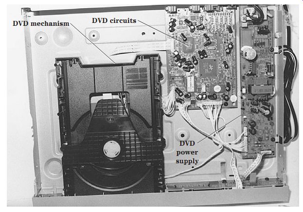
FIG. 6 Try to locate the various components on the topside of a DVD/CD player.
Disassembly of a Panasonic DVD/CD changer
Remove the four screws that hold the top cover of the DVD/CD changer, two on each side of the unit. Remove the two screws at the top and rear for top cover removal. To remove the front panel, remove the three metal screws at the bottom edge and the two screws, one on each side, of the plastic front cover.
Remove the four screws that hold the tray assembly at the rear panel. Remove two screws, three connectors, and four FFCs from the top of the tray assembly. A closed lock gear on the left side of the tray assembly must be pressed to release the plastic tray assembly. Pull the tray assembly toward the front, and remove all connecting cables.
Push and release the four claws, and then remove the tray assembly.
Disassemble the rear panel by the removing 10 screws at the rear of the DVD/CD/VCR player. Remove the clamper plate assembly by removing the two screws, one on each side, mounted on the plastic clamper. Push out the claw clamp at the corner, and the clamper plate assembly can be raised upward. To disassemble the fixed plate, magnet, and clamper, release the three claws inside the round clamper plate assembly. Extreme care should be used when removing the loading mechanism, back-end module, and middle chassis. Make a diagram or screw-mounting drawing and lay the parts in line so that the components can be replaced without any difficulty and without any service literature.
After replacing the DVD/CD/VCR changer, the traverse unit must be left in a standby position. Press the open/close button to close the loading tray. Press the power button to turn the power off. Now disconnect the power plug from the ac outlet. Do not disconnect the power plug from the ac receptacle with the tray open. If you try to close the tray manually, the traverse unit will not go to the upper (standby) position, and the player cannot be handled or transported.
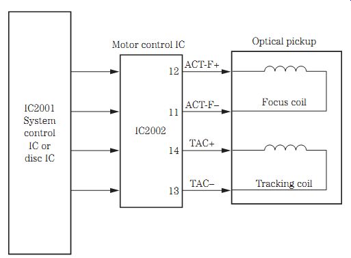
FIG. 7 The tracking and focus coils are driven by a motor driver IC that
is controlled by a system control IC or microprocessor.
The focus and tracking coils
The purpose of the focus servo circuits is to keep the laser beam focused correctly on the pits of the disc surface. The focus circuits detect the focus error signal and are used with the FOK circuit to determine the focus adjustment timing. The focus circuits shift the objective lens up and down to find the correct focus point. A signal from the processor or system control IC controls the focus driver IC or transistors that are tied to the focus coil. All the latest focus coil circuits are controlled by a mo tor driver IC. The focus and tracking coils operate the same as in early CD players.
The purpose of the tracking servo system is to place the laser beam directly in the center of the pit track both laterally and horizontally. Tracking coil assembly movement is horizontal, where the focus coil assembly moves closer or further. The tracking error signal from the pickup optical assembly goes to the servo IC, which drives a tracking coil driver IC (Fig. 7). The tracking driver IC provides voltage to the tracking and focus coil assembly located in the optical pickup assembly.
In a Panasonic DVD/CD/VCR player, the focus and tracking motors are driven by a motor driver IC that is controlled by a DSC microprocessor. The spindle and traverse motors are driven by the same motor driver IC. Separate motors drive the focus, tracking, spindle, and traverse operations instead of coils in DVD/CD/VCR players (Fig. 8).
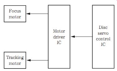
FIG. 8 The focus and tracking motors are driven by a motor driver IC from
a DSC microprocessor in a DVD/CD/VCR player.
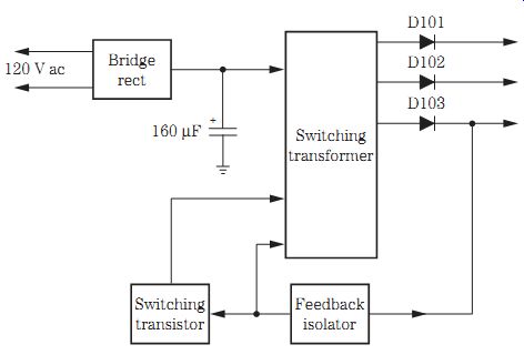
FIG. 9 Block diagram of a switching power supply found in a DVD/CD player.
Low-voltage power supplies
Most low-voltage power supplies found in DVD/CD players consist of transformer switching circuits. The normal 120-V ac input is like most low-voltage power supply TV circuits. A bridge rectifier produces a high dc voltage to the switching trans former and switch-drive transistor. The switching transistor provides a switching off and on path in the primary side of the switching transformer that produces a magnetic field to create a voltage in the secondary winding of the transformer.
A switching power supply or a switch-mode power supply (SMPS) is found in DVD/CD players (Fig. 9). These same switching circuits are found in present-day TV circuits. No on/off switch is found in the input circuits of the switching power supply.
Several half- and full-wave silicon diode circuits are found in the various voltage sources in the secondary winding of a switching transformer. A photocoupler or isolator provides feedback from the secondary winding source to the primary winding of the switching transformer. Low-pass-filter (LPF) transistors may be found in the different voltage sources. Some DVD/CD player power supplies have only transistor voltage regulators within the various voltage sources. IC voltage regulators are found in the larger voltage sources. A switching IC, instead of a switching transistor, may be located in more recent switching power supplies.
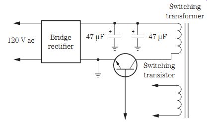
FIG. 10 Block diagram of a DVD/CD changer low-voltage power supply with a
common input ground.
The switch-mode power supply (SMPS) input circuits are above the ground that is called a hot ground. When taking voltage measurements on a switching transistor or IC component, make sure that the ground clip of the voltmeter is connected to the hot ground or a bad voltage measurement will occur. Remember, the main low-voltage in put is at the hot ground side. All components tied to the primary winding of the switching transformer are at hot ground potential. Clip the ground or black lead of the voltmeter to the main filter capacitor hot ground for accurate voltage measurements within SMPSs or switching power supplies.
A signal processor or secondary windings of the switching transformer operate at a cold or common ground. All voltage measurements within the secondary windings of a switching transformer can be taken at the common or cold ground. Again, use the main filter capacitor negative terminal as the common ground side. Some low-voltage power supplies with a switching transistor and transformer have a common ground on the secondary side (Fig. 10).
The main filter capacitor in a DVD/CD player is not as large as that found in a TV chassis. A TV main filter capacitor may be 470 to 680 uF and 150 to 200 V, whereas two 47- uF electrolytics are found in the parallel filter circuit of a DVD/CD player. Determine if the main filter capacitor has a common or hot ground before taking critical voltage measurements.
The secondary voltages in a DVD/CD player are usually 5-, 8-, and 12-V sources. A higher 20 to 24 V dc is fed to the display circuits. The DVD/CD/VCR deck has UNSW +14-V, audio +15.7-V, and UNSW +33-V sources. The regulated output voltages in a DVD/CD changer are at 2.5, 5, and 9 V. You may find several voltage control switch and current-limiter switch transistors within the DVD/CD output circuits. Transistor and IC voltage regulators are found throughout the secondary voltage sources.
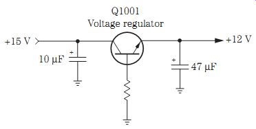
FIG. 11 The output supply voltage is taken from the emitter terminal of a
transistor regulator.
Transistor regulators
Although most of the latest DVD/CD players contain IC voltage regulators, transistors are found in switching, LPN, and voltage regulator circuits. The positive voltage source is taken from the emitter terminal of the transistor and filtered with electrolytics in the output voltage source. A transistor voltage regulator works as a series regulator, whereas a zener diode appears in a shunt-type regulator. The regulator circuit stabilizes the rectified-filter power supply, keeps the voltage source stable, and does not vary with a change in load (Fig. 11).
A defective transistor regulator can appear intermittent, open, or leaky. An intermittent voltage measured at the regulator output emitter terminal can produce intermittent operation at the voltage regulator source. An open transistor regulator has no or very little voltage at the output voltage source and produces a dead symptom. A shorted transistor regulator can produce a lower dc voltage output, and the voltage on all three terminals of the transistor may indicate a common low voltage. Critical voltage input and output tests on the transistor voltage regulator can indicate a defective transistor voltage regulator. Take a transistor in-circuit test with the diode tester of a digital multimeter (DMM) or transistor tester if in doubt. Also check the switching transistors with the diode tester of a DMM.
IC voltage regulators
The latest IC voltage regulators are found in DVD/CD player chassis. A regular IC voltage regulator has input, output, and ground terminals. The shunt IC regulator may appear as an internal zener diode or a multi-terminal voltage regulator (Fig. 12). An adjustable IC voltage regulator might have four or five connecting terminals.
IC shunt, digital voltage IC, and motor IC regulators (9 V) are found in several DVD/CD players.
An open IC voltage regulator will have very little or no voltage at the output terminal. The shorted or leaky IC voltage regulator may have a low voltage at the output terminal. Suspect an intermittent IC regulator when there is a varying voltage on the output and a normal voltage on the input terminals. Take critical input and output voltage measurements with a DMM on the suspected IC to determine if the IC regulator is defective.
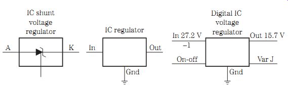
FIG. 12 The different types of IC voltage regulators found in today's low-voltage
power sources.
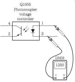
FIG. 13 Testing the photo-coupler with the diode tester of a DMM.
Photocoupler or isolator
The switching transformer power supply circuits have a photocoupler or isolator IC that provides feedback from the output secondary voltage to the primary side of the transformer. An optical isolator IC provides the same results in switch-mode power supply (SMPS) circuits. The optical isolator contains an internal light-emitting diode (LED) and a photodiode or transistor in one package. The optical isolator with the switching transformer isolates the secondary (cold) ground from the primary (hot) ground. An LED is found on the secondary voltage side, and the photodiode or transistor is at the input circuits (Fig. 13).
Test both sides of the voltage-controlled photocoupler or isolator with the diode tester of a DMM. A diode measurement on the LED side will be at least twice the resistance measurement of a normal silicon diode in only one direction. If terminals 1 and 2 show a resistance measurement in both directions with the diode tester of a DMM, suspect a leaky coupler or isolator. Pin terminals 3 and 4 should show no resistance with reversed test leads.
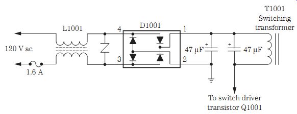
FIG. 14 A typical low-voltage bridge circuit found Troubleshooting low-voltage
circuits
Troubleshoot the low-voltage circuits in a DVD/CD player as in a TV chassis. Quickly check the dc voltage across the main filter capacitor. No voltage here may indicate an open fuse, isolation resistor, or bridge rectifier. Most DVD/CD players employ a bridge rectifier circuit instead of single silicon diodes. The low-voltage bridge rectifiers work directly off the 120-V ac power line as in a TV chassis.
Low dc voltage across the main filter capacitor may indicate a leaky or shorted diode or a defective electrolytic capacitor. Unplug the DVD/CD player from the ac outlet, and check each diode within the bridge component with the diode tester of a DMM. Suspect open diodes within the bridge circuit when there is no or very little output voltage if the power line voltage is at the input terminals of the bridge rectifier.
Sometimes a defective electrolytic filter capacitor can have lower capacity and cause a lower dc output voltage from the power supply. Check for an equivalent series resistance (ESR) loss and different capacitance of the main filter capacitor with an ESR meter. If the capacitor shows ESR capabilities or a loss of capacity, replace it. A defective main filter capacitor may cause the chassis to not start up or to start up and then shut down. Usually, a lower dc voltage is measured across the main filter capacitor if the component is leaky or defective. Remember, the output voltage on the main filter capacitor is much higher than that found in secondary voltage sources.
If an ESR meter is not handy and low voltage is measured at the main filter capacitor, pull the ac cord out of the wall receptacle. Clip a higher or same capacity and voltage electrolytic across the suspected capacitor. Now power the unit up and take another voltage measurement. Always observe the correct polarity of the electrolytic capacitor. The dc voltage should rise to normal when the original capacitor has lost its capacity or has ESR problems. Replace the defective electrolytic with one of the same or higher capacity and working voltage (Fig. 14).
Troubleshooting the switching power supply
Servicing the switching power supply in a DVD/CD player is the same as troubleshooting a TV switching power supply. Check the dc voltage across the main filter capacitor.
If no or low dc voltage is found across the main filter capacitor, check the low-voltage circuits. Check all isolation resistors, bridge rectifiers, and electrolytic capacitors.
Go to the switching IC or transistor when high dc voltage is found across the main filter capacitor and there are no secondary voltage sources. Take critical voltage measurements on the switching transistor. Very high voltage on the switching transistor collector terminal indicates an open transistor or emitter resistor if one is found between the emitter leg and hot ground.
Most switching transformer power supply problems are caused by the switching transistor or IC. This switching transistor can appear leaky, shorted, or open. A shorted switching transistor may open the main power line fuse. Do not overlook an open or leaky voltage control switch transistor within the base circuit of the switching transistor.
Sometimes a switching transformer is found to be bad, but very seldom. The switching transformer should be replaced with the original part, although some switching transformers are now available. Check for open or burned resistors within the switching transistor or IC circuits.
Check the secondary voltage on the silicon diodes within the switching transformer sources. When a certain section of a DVD/CD player does not function, always check the dc voltage source. Check the voltage across each secondary filter electrolytic net work with a quick voltage measurement. The output voltages in the secondary sources will vary form 3.3 to 12 V.
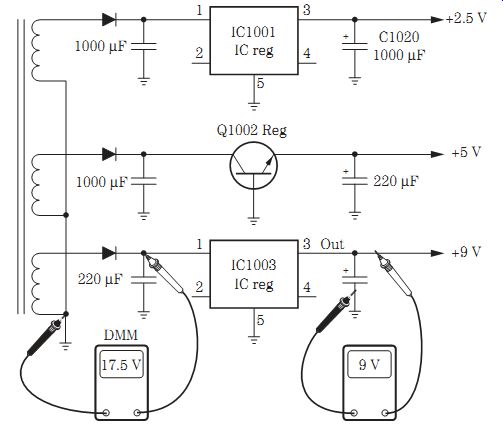
FIG. 15 Checking the secondary voltage source with the diode tester of a
DMM.
Simply measure the electrolytic working voltage on the capacitor when a schematic is not available. The measured voltage will not exceed the working voltage found marked on the electrolytic capacitor. By quickly measuring the dc voltage on each silicon diode or corresponding filter capacitor, you can locate a defective low-voltage source (Fig. 15). Double-check the electrolytic with an ESR meter.
When all the secondary voltages are found across all filter capacitors, go to the in put and output terminals of the IC regulator. Measure the input voltage on the collector terminal of the transistor regulator. The normal output dc voltage on the emitter terminal will be less than that found on the collector terminal. Again, check the working voltage marked on the electrolytic capacitor at the output voltage source.
For instance, a filter output capacitor with a 1000- uF, 25-V rating works in a 13- to 15-V output source. The 10- to 47- uF, 6.3-V electrolytic may be located in a 5-V source.
A 10- to 47- uF, 50-V electrolytic filter may be located within a +33-V source. A 220- uF, 16-V electrolytic filter may provide a smooth filter action for a 9-V motor source. Re member, the working voltage of an electrolytic filter capacitor will always be higher than the actual voltage source. Check all electrolytic capacitors within the low-voltage and switching power supplies with an ESR meter.
The DVD/CD/VCR player power supply
The low-voltage power supply found in a DVD/CD/VCR player may be composed of two different power supplies. The two switching power supplies have a switching transformer and transistor operating within the switching circuits, whereas the other power supply may have a switching IC component. Both switching power supplies may be protected by the same 3-A fuse. A bridge rectifier in each power supply may contain a bridge rectifier or separate silicon diodes and be filtered by an 82- to 150- uF electrolytic capacitor. The input switching power supply circuits have a hot ground, whereas the secondary circuits of the switching transformer have a cold ground (Fig. 16).
A feedback isolator or voltage error detector IC provides feedback from the secondary voltage source to a separate primary winding. The hot and cold grounds are isolated by the switching transformer and the error switching detector or isolator IC. When taking voltage measurements within the switching input circuits, take the measurement across the main filter capacitor, and use the hot ground of the capacitor for other voltage measurements in the input circuits. All secondary transformer voltage sources can be taken from the common (cold) ground side, or use one of the negative ground terminals of a filter capacitor as common ground.
A shunt regulator IC is found between common ground and the isolator error voltage detector in a DVD/CD/VCR player (Fig. 17). The shunt regulator (IC1003) is tied to the LED photodiode within the error voltage detector (IC1005). A diode test with the diode tester of a DMM can indicate a good diode assembly with a low ohm measurement in one direction.
Several secondary windings within the switching transformer have several silicon diodes rectifying the different voltage sources. Fairly large electrolytic capacitors (47 to 100 uF) are found in the secondary voltage sources. Transistor and IC voltage regulators may be found in these voltage sources. A +12- and +5-V source may be connected to the DVD circuits. A separate +5-V source may feed the analog and digital circuits.
Most of the processing ICs operate from the 5-V source.
The second switching power supply provides a voltage source to the VCR circuits.
The 3.3- and 3.6-V sources are developed from an IC voltage regulator in the 5-V line. A 3.3-V source may feed the SD RAM IC. The 3.6-V source may feed the flash-memory circuits. A 5-V source feeds the Syscon, video, and LED circuits, whereas a 12-V source supplies voltage to the switching power on +12-V and power on/off transistors. The _14-V source applies voltage to the UNSW14 Advance processor IC, and the 15.7-V source feeds the audio VCR circuits. You can service the switching IC power supply like the switching transformer circuits in a TV chassis. If a schematic is handy, troubleshoot the waveforms with an oscilloscope.
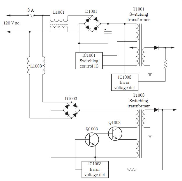
FIG. 16 Block diagram of a switching transformer circuit of a dual power
supply in a DVD/CD/VCR player.
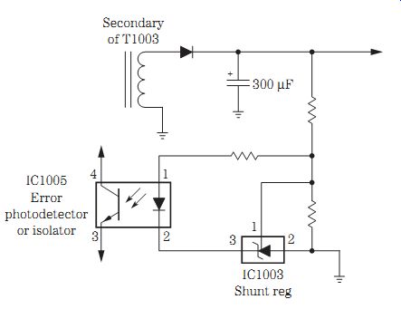
FIG. 17 Block diagram of a shunt coupler between the isolator (IC1005) and
common ground.
Switching transistors
Many different switching transistors are found in a DVD/CD player. The current limiter switching transistor operates in the low-voltage primary circuits of the switching transformer. Several voltage-control switching transistors are found and operate within the secondary winding of the switching transformer. A couple of switching transistors may be found in the switch power on/off of the analog +5-V circuits. Two +9-V motor-switching transistors operate the 9-V motor circuits. Two switching transistors are found in the muting audio output jack circuits.
Switching transistors are located in the power supply that feeds the VCR and turn on circuits within the DVD/CD/VCR player. Switching power-on +12-V and switching power-off transistors are found in the 12-V source (Fig. 18). The switching power-on +5-V transistor is located within the video SW 5-V source. A switching rec on transistor and switch delay rec on-on transistor are found in the system control (servo) circuitry of the VCR section. Suspect a defective in-circuit switching transistor when a certain operation will not function. Check the suspected switching transistor with the diode tester of a DMM. Do not overlook switching transistors located within the hi-fi section of a DVD/CD/VCR player.
Chips and more chips
There are many surface-mounted device (SMD) chips found within DVD/CD/VCR player circuits. There are many resistor and capacitor chips in virtually every DVD circuit. Besides SMD transistors and IC components, several chip inductors and chip filters are found in a DVD player chassis. Check the resistance of the chip resistors and inductors with the low-ohm range of a DMM. A chip inductor will have very little resistance. Test the chip capacitors with an ESR meter.
Check each chip transistor with the diode tester of a DMM. Compare the input signal with the output signal of a suspected chip IC or microprocessor. Take a critical voltage measurement on the Vcc or Vdd terminal of a suspected chip IC. Be very careful when checking voltage on a chip IC or microprocessor. Use sharp-pointed test probes on the test equipment so as not to short out a terminal nearby (Fig. 19).
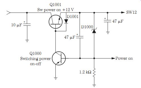
FIG. 18 Switching transistors within the switching power supply circuits
of a DVD/CD player.
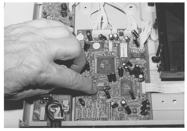
FIG. 19 There are SMD transistors, ICs, inductors, and filters within a DVD/CD
player.
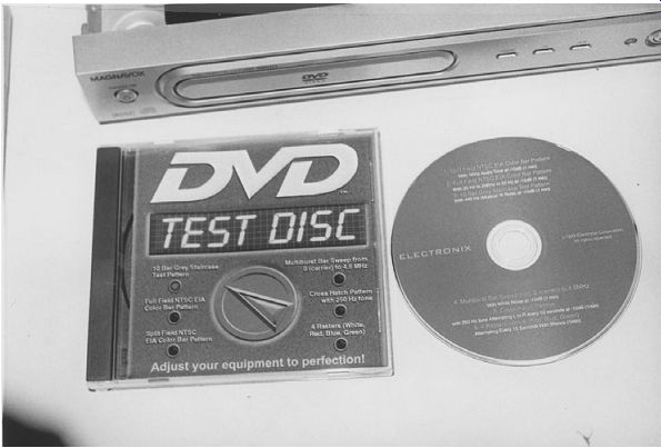
FIG. 20 A DVD test disc can check the color-bar pattern, full-field pattern,
grey-staircase test pattern, multiburst bar sweep, cross-hatch, and white,
red, blue, and green rasters.
The DVD test disc
A DVD test disc provides signals for tilt, luminance level, and color-bar adjustments.
A DVD test disc may provide a split-field National Television System Committee/Electronic Industries Alliance (NTSC/EIA) code-bar pattern with a 1-kHz audio tone. The full-field NTSC/EIA color-bar pattern with 20 Hz to 20 kHz to 20 Hz at -10 dB is found on the DVD test disc. A 10-bar gray-staircase test pattern with 440 Hz (musical A note) at -10 dB is found on the test disc. The DVD test disc may have a multiburst bar sweep signal from 0 (carrier) to 4.5 MHz with white noise at -10 dB. You also may find a cross-hatch pattern with a 250-Hz tone alternating left to right every 10 seconds on the DVD test disc. Most selections are continuous. Silence is used to test audio systems for generated noise, ground loops, and interference (Fig. 20). A DVD test disc (32-16660) can be purchased at MCM Electronics, 650 Congress Park Drive, Centerville, OH 45459-4072.
There are other DVD test discs that can be purchased at most electronics parts distributors. Panasonic has a DVD test disc (DVDT-S01) for electrical adjustments. Check with the service warranty station that you service for its test discs.
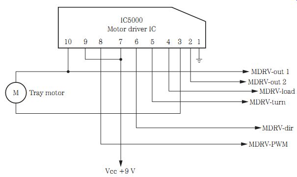
FIG. 21 The tray motor with a motor driver IC in a DVD/CD changer.
Tray motor operations
The tray motor rotates the rotating tray that might hold three or five discs in a DVD/CD changer. The tray motor drives a belt that turns a tray gear that turns the large tray holding the different DVDs. The tray motor may operate from a 9-V source from the power supply or a voltage regulator IC. The 9 V is fed from the power source to pin terminals 7 and 9 of a motor driver IC. The motor driver voltage from motor driver IC500 is found on terminals 3 and 10, which feed voltage to the motor terminals (Fig. 21).
Check the dc voltage across the tray motor terminals to determine if the motor driver IC500 is supplying voltage to the tray motor. If the motor does not operate with a dc voltage found on the motor terminals, take a continuity ohmmeter test across the motor terminals. An open tray motor will have no resistance, whereas a normal measurement has a low continuity reading. No voltage across the motor terminals may indicate a defective motor driver IC. Measure the supply voltage at the Vcc terminals of the motor (7 and 9). Suspect a leaky motor driver IC if no or low voltage is found at the supply terminals. If the voltage is low, suspect a leaky motor driver IC or improper sup ply voltage.
Measure the voltage at the supply terminals (Vcc) on the motor driver IC. Go directly to the low-voltage power supply for the 9-V source. A defective IC voltage regulator can provide no, low, or intermittent supply voltage. Monitor the supply voltage at the output terminal of the tray motor for erratic or intermittent rotation of the tray mo tor. A defective tray motor also can cause intermittent tray rotation.
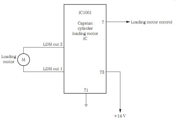
FIG. 22 The loading motor circuits and capstan/cylinder loading motor driver
IC.
Loading motor operation
The loading motor may be controlled by a voltage from the motor driver IC500 that also drives the tray motor or from a separate motor IC. The loading motor in some DVD/CD/VCR units is controlled by a signal from the system control microcontroller to a loading motor driver IC. The microcontroller processor controls the forward, re verse, and stop rotations.
The capstan motor, cylinder, and loading motor may be controlled by the same capstan/cylinder/loading motor driver IC. The loading motor load and unload terminals are LDM out 2 and LDM out 1. The loading motor loads and unloads the disc in DVD/CD/VCR players (Fig. 22). The UNSW 14-V source is fed from the secondary voltage source to the capstan/cylinder/loading motor driver IC.
Check the voltage source applied to the loading motor in either load or unload modes. No or low dc motor voltage may indicate a defective motor driver IC or a bad loading motor. Remove one motor terminal, and take another voltage measurement.
Suspect a bad motor if the supply voltage to the loading motor is higher than normal. A bad motor is indicated by normal drive voltage and no motor rotation. Check the continuity of the motor with the low-ohm scale of a DMM. When motor rotation is erratic or intermittent, monitor the dc voltage at the motor terminals to determine if the driver IC or the motor is defective.
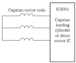
FIG. 23 Block diagram of the capstan mo tor driver IC in a DVD/CD/VCR player.
Loading motor belt problems
Most loading and capstan motors have a drive belt. A worn, loose, or stretched mo tor belt can cause intermittent or erratic loading. The loading motor belt with grease or oil on it may result in erratic loading. A worn and stretched loading motor belt can come off the pulley into the gear area, resulting in no loading. A cracked or broken belt can cause the disc not to load. Check all belts when the disc will not load or a cassette will not load in a VCR player.
Clean the old, hardened grease or oil off the capstan motor and drive belt when the capstan motor speed is slow or the belt drags and produces a wow and flutter tape speed. A worn or loose capstan belt can cause a garbled audio sound. A dry or frozen capstan bearing can cause the capstan belt to slip. Loss of playback and recording functions can be caused by a cracked or broken capstan drive belt. The broken capstan belt results in no rotation of the tape in the VCR. Realign the new belt if it is too loose or keeps coming off the motor pulley.
Capstan motor circuits
The capstan motor circuits within a DVD/CD/VCR player may operate from the same driver IC as the loading and cylinder motors. A capstan motor assembly may include the capstan motor Hall elements, MR head, cylinder, Hall IC, capstan motor, and the motor control IC. Troubleshoot the capstan motor as in any VCR (Fig. 23). The capstan motor may operate from a 12- or 14-V source.
A defective capstan motor or frozen motor bearings can cause the tape to become stuck in rotation. Improper or low dc voltage applied to the capstan motor can cause a dead rotation or slow speeds. Sometimes the bad capstan motor can open the low-ohm resistors in series with the motor and supply voltage source. A flat armature or a dead spot with no rotation can occur in a defective capstan motor. Try rotating the motor pulley by hand when the capstan motor is dead and then takes off. Simply replace the defective capstan motor.
Take a low-voltage measurement across the capstan motor terminals. Suspect a bad motor if a normal dc voltage (9 to 14 V) is found at the motor terminals with no rotation. Check the capstan motor driver IC when no or low dc voltage is found at the mo tor terminals. Recheck the motor voltage source with one motor terminal removed from the motor driver IC. Usually, a defective motor driver IC also will cause no rotation in any motor that is connected to the same motor driver IC. Suspect a motor driver IC when none of the motors will operate that are connected to the same driver IC.
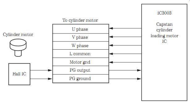
FIG. 24 Block diagram of the cylinder or drum motor IC circuits in a DVD/CD/VCR
player.
Cylinder or drum motor operation
The cylinder motor circuits may consist of a cylinder motor, Hall IC, cylinder or drum motor driver IC, a motor position detector, and a cylinder pulse generator (PG). Service the cylinder or drum motor as in any VCR player. No rotation of the drum motor may be caused by improper voltage to the motor, a poor or defective voltage regulator IC, or a faulty drum motor driver IC. A poor connection between the cylinder motor and the servo IC can cause no cylinder rotation. Check for bad PC board lower drum assembly connections. Open or low-ohm resistors in the voltage source of the cylinder motor can cause no motor rotation. Check for a badly soldered joint on the cylinder circuit board assembly (Fig. 24). The cylinder motor may operate from a 12- to 14-V source.
A defective drum or cylinder motor can cause the tape to load and then the motor to shut down. Bad tape end sensors can cause the tape to load with a motor shutdown symptom. A bad cylinder or drum motor can cause the motor to start and quit with mo tor shutdown symptoms. Suspect a bad cylinder motor driver or servo IC when the motor begins to run and then shuts down. Take critical voltage measurements on the cylinder motor driver IC and servo control processor. Check for an improper voltage source to the driver and servo ICs supplied from a defective IC or transistor voltage regulator source.

FIG. 25 Block diagram of the stepping motor found in a DVD/CD changer.
Stepping motors
Stepping motors are found in a DVD/CD (three- to five-disc) changer. The stepping motors help to load several discs and sometimes are called the up and down motors.
Like all motors found in a DVD player, a motor driver IC drives the rotation of the stepping motors. The optical pickup assembly may be driven by the same motor driver IC2500 (Fig. 25). Check the stepping motors as you would any other motor within a DVD/CD player.
Disc or spin motor operation
The disc, spindle, or turntable motor starts to rotate the disc after it has been loaded in the DVD/CD player. A small platform is mounted at the end of the spindle motor's shaft that spins the CD or DVD at a variable rate of speed. The spindle motor is usually located right under the clamper assembly. The disc motor starts out at 500 rpm and slows down to 200 rpm as the pickup assembly moves toward the outer rim of the CD in a CD player (Fig. 26).
The spindle motor can be controlled with a separate IC or combined with the SLED motor from a motor driver IC500. Check for a dead disc motor by starting at the motor circuits and working toward the servo or microcomputer IC. Check the motor voltage across the motor terminals. If the dc voltage is low or there is no supply voltage, check for a defective motor driver IC501. Measure the supply voltage on the motor driver IC.
Low voltage on the motor driver IC may be caused by a leaky motor driver IC or a defective voltage supply source.
A defective spindle or turntable motor can cause no disc rotation. Suspect a defective motor driver IC when the spindle motor will not stop in the stop mode; a low dc voltage can be found on the disc motor terminals. Check for poor terminal pin connections on the motor driver IC if the spindle or disc motor starts at a high rate of speed. A defective disc motor can cause very high speed problems (Fig. 27).
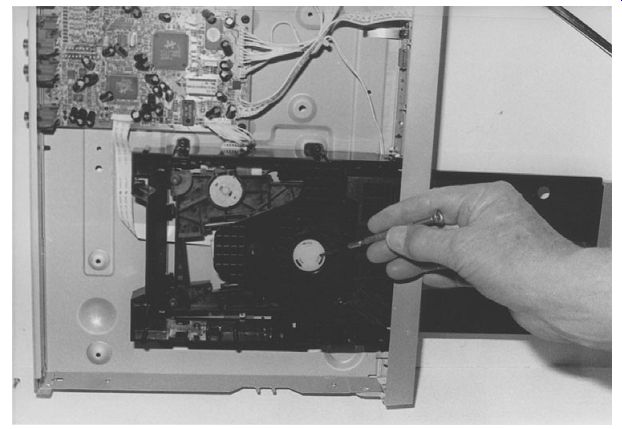
FIG. 26 The spindle or disc motor found in a DVD/CD player.
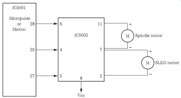
FIG. 27 Block diagram of the motor driver IC to the spindle and SLED motors.
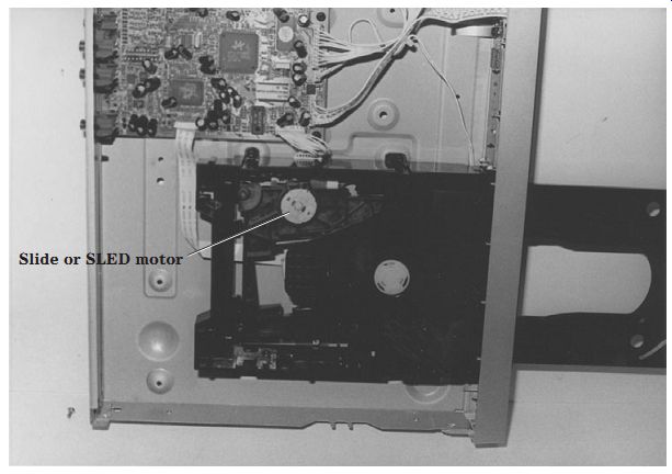
FIG. 28 The SLED or slide motor moves the optical assembly from the inside
to the outside rim of a DVD/CD.
SLED or slide motor operation
The SLED, slide, or feed motor in a CD player moves the optical assembly across the disc from the inside to the outside rim of the CD, keeping the optical lens constantly in line with the center of the optical axis. Usually the motor is driven by a rotating gear that moves the laser beam down one or two sliding bars. The slide motor may have fast-forward and rewind mode operations. A separate spindle and traverse mo tor may be driven from the same driver IC that also may operate the focus and tracking motor in a DVD/CD/VCR player.
Check for a gummed-up track or poor meshing of the pulley and gears when there is erratic or intermittent operation of the slide motor. Notice if the voltage on the slide motor terminals is intermittent. Monitor the voltage on the motor terminals. Erratic or intermittent voltage can be caused by a defective motor driver IC. A defective motor can cause erratic or intermittent rotation of the disc (Fig. 28).
You may find a small motor belt that drives a worm gear pulley to move the pickup assembly in some models. A broken or worn gear belt can result in no or erratic optical assembly movement. Clean the motor belt of oil or grease spots if movement is erratic.
Replace the motor drive belt if it shows any signs of slippage.
Suspect a motor driver IC when the SLED or spindle motor does not rotate if they are controlled by the same motor driver IC. Simply scope the waveforms on and into the motor driver IC. Check the voltage from the motor driver IC to each motor.
If there is no voltage, measure the dc supply voltage (Vcc) to the motor driver IC from the low-voltage source in the power supply. Scope the supply signal from the microcomputer or system control IC with no signal applied to the motor driver IC.
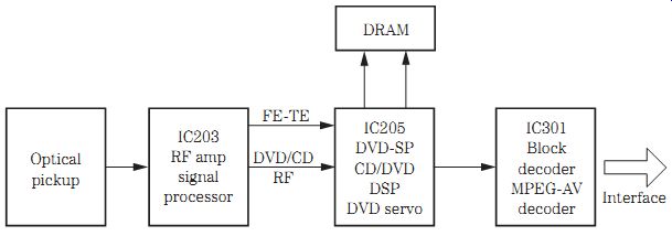
FIG. 29 An early DVD/CD player with an RF amplifier signal processor that
amplifies the RF signal from the optical pickup assembly.
Radiofrequency (RF) preamplifier
In early RCA and Zenith DVD/CD players, the output from the laser optical pickup was fed to the DVD A, B, C, D, DVD RF and CDA, and BEF signals. The RF signal processor is somewhat like the CD RF amplifier circuits. This RF signal is amplified and passed on to a CD/DVD DSP, and DVD servo IC205. The FE, TE, and DVD/CD RF is fed from the RF amplifier IC to IC205. IC205 provides demodulation and C1-C2 error-correction circuits.
The RF signal processor also may include internal RF automatic gain control (AGC) circuits, automatic phase control (APC), internal auto asymmetry, an internal disc effect detector, and an internal focus protect function against disc effects. Scope the output of the RF amplifier to determine if the optical pickup signal and the RF amplifier are normal.
In some models, the servo control phase duration modulation tracking and CD-ROM compatibility are fed from the RF amplifier IC to the servo IC. A RAM buffer or DRAM IC is connected to IC205. The demodulation, corrector, and DVD data are fed from IC205 to the block decoder IC301 (Fig. 29).
System control or microcontroller
Like the standard CD player system control IC, the microcontroller in a DVD/CD/VCR player controls the loading motor operations. The loading motor is controlled by IC8002 to a loading motor driver IC to the loading motor terminals. The system control IC also controls the mode switch positions, reset, power down, drive, and servo data. The take-up reel, take-up photo, and supply photo (TRL) LEDs are controlled by the system control IC.
The Xtal oscillator, safety tab broken, video delay, and PC and clock serial data 1 are controlled by IC8001. The system control IC also operates the DVD ready, DVD reset, host ready, DVD serial data, DVD serial data 1, and DVD serial clock function. IC8002 controls the progressive on, key data (1-5), VCR LED on, VCR rec LED on, DVD LED on, LED on, and progressive LED on operations. The infrared remote receiver signal is connected to pin 5 of the system control IC. A 5-V volt (Vdd) source powers the operations of the system microcontroller (IC8002) (Fig. 30).
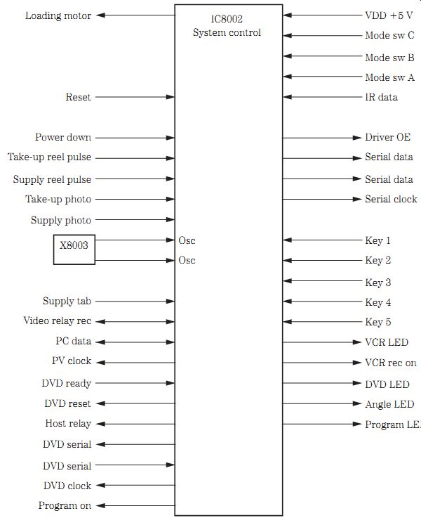
FIG. 30 The system control microcontroller (IC8002) controls many different
operations within a DVD/CD/VCR player.
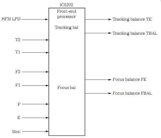
FIG. 31 The DVD front-end processor found in a DVD/CD changer.
Front-end processor
The front-end processor IC receives the DVD audio/video signal from the HFM, DVDM, and CDM optical pickup unit in a DVD/CD changer. In a DVD player, the optical pickup output is fed from the RF amplifier IC. The optical pickup signal from the traverse unit is fed to the front-end processor, and the output is fed to the disc servo and optical disc control process IC in a DVD/CD/VCR player. The front-end processor (FEP) receives the DVD modulation and CDM modulation signal (DVD audio/video signal line) from the optical pickup unit in a DVD/CD player (Fig. 31).
The tracking balance, focus balance, and TE signals are fed to the decoder IC.
A +5-V source is fed to pin 1, and a 3.3-V source is applied to pin 2. Simply scope the input and output of the DVD audio/video signal lines of the front-end processor IC.
Take critical voltage tests on the supply voltage source (Vcc) terminals of the IC front end processor. The tracking and focus balance signal is sent from the front-end processor to the DVD decoder or disc servo control IC.
From the optical pickup assembly in a DVD/CD/VCR player, the optical pickup signal is fed to a front-end processor IC, a disc servo control IC, an optical disc control processor, and a decoder microprocessor (Fig. 32). The same DVD/CD/VCR player's optical pickup unit contains the traverse, spindle, focus, and tracking motors. Here the focus and tracking motors are found instead of coils.
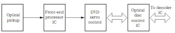
FIG. 32 Block diagram of a DVD/CD/VCR player showing the DVD signal from
the optical pickup assembly to the decoder IC.
DVD digital signal processor IC
The DVD digital signal processor converts the high-frequency input signal to digital with an 8-bit analog-to-digital (A/D) converter. The gain control is set by an AGC circuit for the best performance of the converter. The A/D converter-CLC circuits provide a clocking sync for the preceding operations. The amplifier and equalized RF signal that is fed into the DVD DSP circuits also includes a portion of the DSP signal that is sliced data, which functions as a bit decoder and provides error correction.
MPEG decoder The DVD technologies depend on MPEG encoding and decoding to provide high-fidelity movies and other video programs. The MPEG audio/video decoder IC8002 in a DVD/CD/VCR player receives the host data (16 bits) from the optical disc control IC.
The host IF signal is fed to a DVD decoder and error-correction circuits. IC8102 (64 MB SDRAM) provides clock, an SDRAM address bus, and an SDRAM data bus to and from the error-correction circuits. The MPEG decoder signal is fed to a video signal processing circuit feeding a YUV data (8-bit) signal to the NTSC error IC8201. The video process circuits also provide a horizontal and vertical output sync signal.
The DVD decoder circuit separates the video and audio signals and applies the audio signal to an audio decoder circuit that is fed to a D/A converter (IC8003). A reduced instruction set computing (RISC) processor circuit provides a memory address bus and a memory data bus to and from the flash memory IC8012. The output of the RISC processor is fed to a flip-flop IC8002. A regulated 3.6-V supply source is fed to the MPEG decoder IC8002 (Fig. 33).
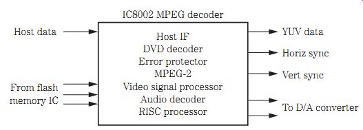
FIG. 33 The MPEG decoder (IC8002) found in a DVD/CD/VCR player.
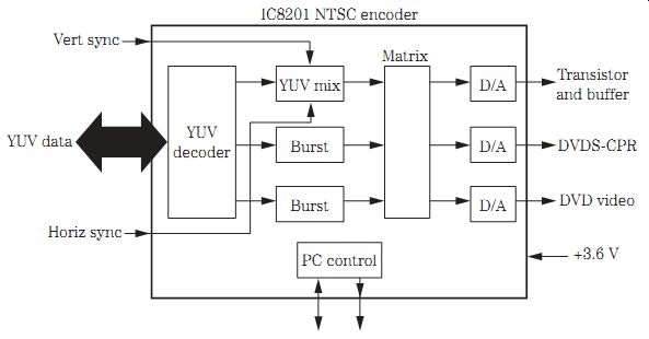
FIG. 34 Block diagram of the NTSC encoder within a DVD/CD/VCR player.
NTSC encoder
The NTSC format has 525 scanning lines, whereas the standard phase alternate line (PAL) format has 625 scanning lines at 50 Hz instead of 60 Hz. A DVD player must play both the NTSC and the PAL standard. This means that additional video is included so that either system can be used.
The YUV data (8 bits) derive from the video signal processor circuits within the MPEG decoder IC. Also, the horizontal and vertical sync signals are fed into IC8201.
The three outlets from the YUV decoder are fed to a sync mix and burst mix to the matrix circuits. The four D/A converter signals are fed from the matrix circuits to a transistor buffer and filters circuits, providing a DVDS-Y/Y, DVD S-C/PR, DVD video, and DVD PB to the video signal path circuits in a DVD/CD/VCR player (Fig. 34).
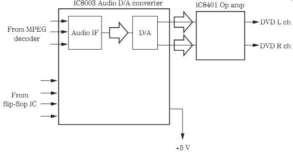
FIG. 35 The audio D/A converter supplies right and left audio signals to
the OP amplifier.
D/A audio converter
The D/A converter IC actually changes the digital signal from digital to analog (audio). An audio decoder from the MPEG decoder IC in a DVD/CD/VCR player is fed into the inputs of the D/A converter IC. The flip-flop IC provides a mode control clock, mode control latch, mode control data, and a reset signal at the input of the D/A converter. The audio intermediate frequency (IF) signal is fed internally to the D/A converter stage, separating the audio into left and right audio signals (Fig. 35).
The D/A converter within a DVD/CD changer is fed SCK, data, LRCK, and BCK from the A/V decoder. The D/A audio output is tied into two different OP amps before it is fed to the RCA right and left output jacks.
The D/A converter circuits can be serviced in the same manner as within a CD player. Check the audio signal with the oscilloscope and at the left and right output jacks. The audio signal can be signal traced from the output of the D/A converter to the audio IC amp. Scope the left and right input audio into the OP amp and at the output terminals to the right and left output jacks. You also can check the audio from the D/A converter stage with the external audio amplifier. One or two audio OP amps may be found in other DVD/CD players after the D/A converter IC.
Scope the input terminals of the D/A converter IC when there is no left or right output signal. If the audio signal from the audio decoder is found into the D/A converter and not at the output, suspect a defective D/A IC or an improper voltage source. When a scope is not available, check the audio output from the D/A converter IC with an external audio amplifier.
Try to locate the 5-V source with a DMM. A very low voltage source may indicate a leaky D/A IC or an improper voltage source. Remove the voltage supply pin from the D/A converter from the PC wiring. Notice if the voltage returns close to the 5-V source. Suspect a defective voltage regulator source if the voltage is still low or there is no voltage. Replace the leaky D/A IC if the 5 V returns to normal. Most circuits found in a DVD/CD player can be serviced like those found in a CD player.
Transistor muting
Like most CD and DVD players, the audio output is muted before the audio output jacks. The audio signal is fed into the collector terminal of the right and left audio lines, providing muting of both audio channels. The base terminal of each muting transistor is controlled by a switching or system control IC. Muting of the sound is accomplished when mechanical operations occur and should not be heard within the audio channels.
Remove the collector terminal when one or both muting transistors have no sound in the audio output channels. If the sound output is intermittent, check the muting transistors. Test each transistor when one or both cut off the sound all the time. Suspect a switching transistor or system control IC if both muting transistors are normal (Fig. 36).
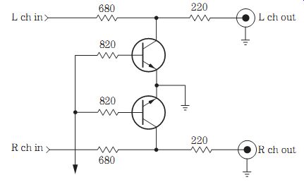
FIG. 36 The left and right audio muting transistors in a DVD/CD player.
Remote control operations
Check the remote transmitter as discussed in Chap. 12. Suspect a defective infrared receiver when the remote control transmitter can operate certain functions within other electronic products. Usually the infrared signal from the infrared receiver is fed into the system control IC. The infrared receiver picks up the infrared signal from the remote transmitter and feeds it into the infrared data of the system control IC.
Check the supply voltage on the infrared receiver, which is fed by a 5-V source.
Suspect a 5-V regulator IC when the voltage is low at the infrared receiver. Remove the 5-V pin terminal from the infrared receiver, and take another measurement.
Check the IC components within the receiver when the 5-V source is normal. Scope the output terminal (3) or at the test point to prove that the infrared receiver is functioning (Fig. 37).
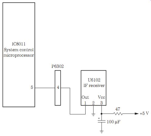
FIG. 37 The infrared receiver circuits in a DVD/CD/VCR player.
DVD troubleshooting chart
Most CD player problems are the same as those found in DVD/CD players. Check Table 1 for additional DVD/CD player service problems and solutions.
Table 1. Troubleshooting DVD/CD player problems.
==============
Problem | Procedure
----------
Basic troubles
No power No power supply Mechanical problems Optical pickup assembly Circuit problems
Actual DVD/CD problems:
Dead, no power No play Play fails to start Plays only part of disc Disc will not load Intermittent skipping Improper tracking Disc starts to play and stops Disc spins slowly, will not play completely Tray will not move back and forth Will not spin, skips, and stops
No video or audio No picture Picture distorted during T rapid advance No audio in the left channel No audio, dim display Noisy audio Program cannot be viewed on TV No audio while disc is playing Improper tracking
Distorted or garbled audio Disc changer will not play No muting during program mode Protection relay will not turn on or off speakers
------------
Check power off/on switch Check connecting cables
Check fuse Check bridge rectifiers Check main filter capacitors with an ESR meter Check switching transistors and ICs
Check tray loading Check loading motor Check traverse unit
Check laser diode with laser meter Scope RF waveforms on RF amp Replace OPU if no function
Check LD drive Servo system control, traverse, focus, and tracking disc servo Signal processing IC or microprocessor Flip-flop IC D/A converter
Check ac fuse Check bridge rectifiers Test electrolytic capacitors
Make sure disc label is up Recheck power cord at receptacle Check ac fuse When will not play outer disc, check ribbon cable to optical assembly
Check deck for DVDs, video CDs, and CDs Dirty disc can cause reduced video and audio, clean disc Clean disc Try another disc Make sure label side is up
Open resistor in carriage motor circuits Gummed-up rails Clean with alcohol and cloth Clean laser lens assembly with alcohol and Q-Tip Check voltage regulator IC to disc motor
Check bad loading belt Check disc reverse switch Dirty mechanism Broken worm gear Tray binding, clean up Spray and clean loading switch Replace defective loading motor Check voltage to loading motor Check voltage at loading motor IC Test each electrolytic in power supply with an ESR meter Check loading switch Replace defective loading motor
Clean lens assembly Worn receptacle, unstable clamper Check table height Bad worm gear assembly Replace disc motor
Clean lens assembly Check tracking coil movement Test tracking driver motor IC
Check driver motor IC regulator Replace split laser, head gear
Clean lens assembly Clean timing mirror Check for scratched lens assembly Check flat ribbon cable to optical pickup
Make sure TV is on Check all connecting cables Check DVD and TV hookups Try another disc
This is normal on most DVD players Check TV to DVD connections Check all cable connections Set VEN/TV to selector TV Turn the TV to the right channel
Check audio from the D/A converter to audio output jacks Test audio from D/A converter with external audio amplifier Check D/A converter supply voltage Replace D/A converter for no audio Replace demodulator IC Bad decoder IC Suspect leaky coupling capacitors Open resistors in audio output Check audio OP amp ICs Check defective muting transistor
Check voltage regulator source Replace defective regulator Solder bad terminals on decoder IC
Replace D/A converter Check filter capacitors with an ESR meter Replace IC OP amp with static in both channels Replace optical pickup with static noise while playing Replace RAM IC for high-pitched noise in sound Replace RAM IC for ticking noise in audio Replace D/A converter for noise in background Replace crystal for low-level noise in the audio Check audio output jacks with the external audio amplifier to check output stages
Replace D/A converter Replace RAM IC Replace defective OP amp IC Check for change in resistance in audio output circuits Check all coupling capacitors with an ESR meter Troubleshoot the audio output circuits with scope or external audio amp Check muting transistors Check system control IC Replace mechanism micro IC Check protection relay Clean points on relay Check for poorly soldered connections on the relay Replace defective zener diode Check silicon diode across relay coil Check all connections on regulator transistor
Replace worm gear and level assembly
============