The compact disc (CD) first appeared on the market in late 1982; and since that time a large number of CD players have made their appearance.
Whilst the CD player is a world-wide standard that utilizes a laser beam to extract the information from the disc, the methods of mechanical and electronic circuitry that eventually enable the information to be effectively extracted and reproduced are various. Some CD players can prove to be quite reasonable to service, whilst others are not, usually because of accessibility, or rather the lack of it, numerous adjustments, or the lack of them, and especially some mechanical adjustments that mystify or frustrate when the required results fail to materialize.
The aim of this guide is to help engineers to achieve a reasonable understanding of CD technology, especially those who have recently decided 'to give CD a go' and engineers newly into the profession. A down-to-earth approach has been applied wherever possible throughout the guide.
The guide is not intended to replace the service manual (no complete circuit diagrams have been included), but to complement the service manual so that the engineer can, hopefully, achieve an appreciation of some of the circuit intricacies.
Before delving into the depths of CD players themselves, it is worthwhile to consider what is actually on the CD itself, as this will provide a reasonable appreciation of some of the relevant circuits as they are approached in terms of terminology and as to why certain things 'happen', either on the disc or in the player.
As various generations of CD players have appeared, whether for the domestic hi-fi or the in-car markets, numerous improvements, innovations and developments have continually taken place, but whatever those various developments may have been, the CD itself still remains in the same original format.
The compact disc: some basic facts
There are two sizes of CD, i.e. 8 cm and 12 cm, with the starting speed of either size of disc being in the region of 486-568 rpm, and the scanning of the disc commencing from the centre. As the CD continues to be played towards the outer edge of the disc, the actual rotation speed slows down so that the disc maintains a constant surface speed as it passes a laser beam which retrieves the data information from the disc.
The constant surface speed of the CD passing the laser beam is in the region of 1.2-1.4 m s-1, and this is referred to as constant linear velocity (CLV), whereas the fixed speed of 33 1/3 rpm of a vinyl record was referred to as constant angular velocity (CAV). The important difference between the two types of drive is related to the fact that more data or information can be effectively 'packed' onto a CLV disc compared to the CAV system. Again comparison with a vinyl record reveals that the surface speed of the record at the outer edge was much faster than at the centre, indicating that the analog audio information was effectively more 'stretched out' at the outer edge compared to that nearer the centre.
The normally accepted maximum playing time for the 12 cm disc is in the region of 74 min, whilst the maximum playing time for the 8 cm disc is around 20 min, but by pushing the limits of the manufacturing tolerances increased maximum playing times can be made possible.
The finishing speeds of the two sizes of disc are approximately 300-350 rpm for the 8 cm disc, and 196-228 rpm for the 12 cm disc, with the actual finishing speed being related to which ever surface speed was chosen, within the range of 1.2-1.4 m s^-1, at the time of recording the disc.
The compact disc: what information it contains
The audio analog information to be recorded onto the disc is regularly sampled at a specific rate in an analog to digital converter (A to D converter) with each sample being turned into digital data in the form of 16 bit binary data words (Fig. 1.1). There are 65,536 different combinations of the 16 bit binary code from all the 0's through to all the 1'sJ and the sampling frequency used for the CD system is 44.1 kHz. With a stereo system of recording there will be two A to D converters, with one for the left channel and one for the right.
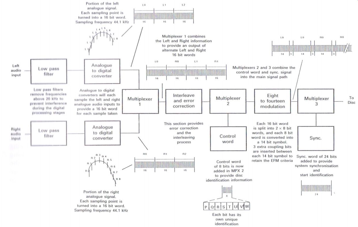
Figure 1.1 Basic CD recording process
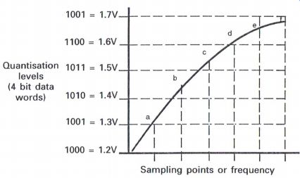
Figure 1.2 Quantization errors
The process of sampling the analog information is refer red to as quantization, and the overall operation can produce certain effects such as quantization errors and aliasing noise.
Quantization errors
Whenever an analog signal is sampled, the sampling frequency will represent the actual times of measuring the signal, whereas quantization will represent the level of the signal at the sample time (Fig. 1.2). Unfortunately, what ever the length of the data word that portrays or depict s a specific sample of the analog signal, quantization errors will occur when the level of the sampled signal at the moment of sampling lies between two quantization levels.
As an example, consider a portion of an analog signal, which for convenience of description is converted into a 4 bit data signal. The analog values shown in Fig. 1.2 each relate to a specific 4 bit data word. The sampling point s indicate the moment when the waveform is sampled in order to determine the relevant 4 bit data word.
The example indicates that at the moment of sampling, the instantaneous value of the wave form lies between two specific data words, and thus whichever data word is selected will comprise a quantization error , which in turn will reflect an analog error when that digital information is converted back int o analog form at a later stage.
This problem will be related to the specific frequency of the analog signal, and also the length of the data words.
The lower pass filter and digital to analog converter
here is no intention of delving int o the intricacies of converting the or signal analog information int o digital data, as there are many excellent reference books available that pursue this particular topic. During the process of recording analog information onto the CD, the audio frequencies are first of all passed through a low pass filter before being applied to the A to D converter as shown in Fig. 1.3 for die left audio channel. The purpose of this filter is to remove all audio frequencies above 20 kHz.
When die audio signal is converted from analog to digital, the signal is sampled at regular intervals, and the value that is obtained at each sample interval is in turn converted int o a 16 bit digital signal.
The sampling frequency for CDs is 44.1 kHz, which is the standard determined to provide the lowest acceptable sampling frequency that will enable the audio spectrum of 0-20 kHz to be reproduced as faithfully as possible, following a criterion stated by Nyquist , an American engineer , in 1928.
---------------
Nyquist criterion
Basically, if an analog signal is digitally sampled, and providing you sample that signal at a rate of at least twice the highest frequency in the bandwidth that is being used, it is possible to reproduce faithfully all the frequencies within that bandwidth. The reason for sampling at a rate of twice the highest frequency is to ensure that at least one sample takes place during the positive half cycle, with the same applying for the negative half cycle.
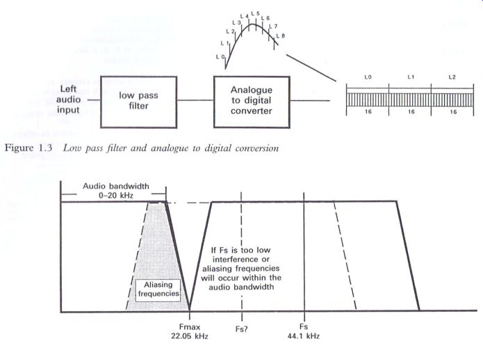
Figure 1.3 Low pass filter and analog to digital conversion
Figure 1.4 Frequency spectrum showing the effects of aliasing if the sampling frequency is too low
Thus with CD3, the audio bandwidth being from 0-20 kHz, the logical sampling frequency would be 40 kHz, but to ensure that effects such as aliasing are minimized, the standard was set at 44.1 kHz (Fig. 1.4). As previously mentioned, the audio signal is first filtered via a low pass filter to remove frequencies in excess of 20 kHz, the reason for this process being to minimize the effect of aliasing, which can be caused when frequencies above 20 kHz are passed through to the A to D converter.
Aliasing frequencies
The A to D converter can, in effect, sample frequencies above the audio range to produce resultant frequencies that can occur within the audio range.
Consider a sampling frequency in the A to D converter of 44 kHz. If a frequency of say 33 kHz, as a result of harmonics outside of the normal listening range from a particular musical instrument, were to be present and therefore sampled, a resultant aliasing frequency of 11 kHz would become apparent. In fact as these harmonics approached the sampling frequency, a range of descending frequencies could be present.
As the analog information is processed into digital data, in the form of 16 bit data words, there will in effect be a 'natural' clock frequency regarding this data information, which is related to the sampling frequency and the number of bits in a data word. For the A to D converter processing either channel of the stereo audio information, this clock frequency will become 44.1 kHz x 16 = 705.6 kHz.
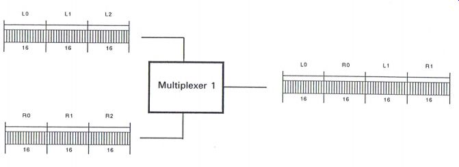
Figure 1.5 Purpose of Multiplexer
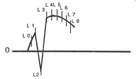
Figure 1.6 The effect of erroneous data (words)----Small section of the
left signal, with an erroneous L2 data word causing an undesirable signal
or 'glitch' at that moment in time as a result of incorrect data due to
scratches or dirt on the surface of the CD.
During the process of preparing the analog information for recording onto the CD, and after each of the left and right analog signals have been sampled and converted into a series of 16 bit data words, there are now effectively two separate channels of data information which now have to be placed onto what will become a single track on the CD. This is achieved by passing the separate left and right data words into a multiplexer, the output of which will be a series of alternate left and right data words, with the left data being the first data word from the output, and thus the first audio data word to appear from the CD (Fig. 1.5).
It is a requirement of the CD specification that the first audio information data word to be laid on the CD track is to be a left data word. This is to enable the decoder within the CD player to 'know' that the first audio data word output from the decoder will be a left data word, so that this data word will be 'directed' towards the left audio channel for subsequent processing. Accordingly the next data word will be a right data word, which will in turn be 'directed' towards the right audio channel.
As a result of this alternating procedure, the natural clock frequency of the data stream must be increased in order that the audio information can be maintained within the correct time-scale.
The bit or clock frequency will now increase by two times to 705.6 kHz X 2 = 1.411200 MHz.
Error correction
Whilst there are benefits to be gained from the process of digital audio recording as used with the CD, such as the improvements in the dynamic range, signal to noise ratio and also stereo separation, when compared to the good old-fashioned vinyl analog recordings, problems do arise when some of the data information become corrupted for some reason or other.
Corruption of the digital data can occur during the manufacturing process of a CD, or as a result of improper care of the disc causing scratches and dirt in various forms to be present on the surface of the disc. These effects can cause incorrect data words which in turn provide an unsuitable output.
-------------
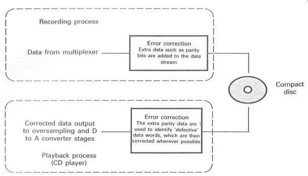
Figure 1.7 The error correction process.
Recording process
Data from multiplexer
Error correction
Extra data such as parity bits are added to the data stream
Compact disc
Corrected data output to D/A converter stages
Error correction , The extra parity data are , used to identify 'defective' data words, which are then corrected wherever possible
to oversampling and D to A
Playback process
------------------
Unfortunately the CD is not as indestructible as one was first led to believe; in fact, the treatment of a CD should be on a par with the treatment of a vinyl long-playing record. Those original 'raspberry jam' demonstrations when CDs were first unveiled have a lot to answer for.
The main physical advantage of the CD is that it does not wear in use as there is no mechanical 'stylus' touching the surface of the disc, with the data being read from the disc via a reflected beam of laser light.
So how does error correction take place? Basically, extra information, such as parity bits, is added to the data stream and eventually recorded onto the CD (Fig. 1.7). When the disc is being played in the CD player, the extra information will assist in identifying any defective words as the data stream is being processed. The error correction stage within the CD player will apply certain types of correction depending upon how many errors are present. This is an extremely complex process, and there are excellent references available to provide the enquiring mind with further information. Here it is sufficient to say that by the addition of this extra information, it is possible for the cd player to identify and endeavor to 'correct' the errors if they are within certain criteria; or if the errors exceed these criteria, the audio output can be muted. If the errors prove to be too difficult to handle, the CD player will usually 'throw in the towel' and shut down as far as the operation of that particular disc is concerned.
How are the errors corrected?
It is useful at this stage to consider, in a very basic form, how the errors are effectively 'corrected' within the CD player.
In Fig. 1.8 we consider the sampled section of an analog signal, compared to the same sample when one of the data words has gone on 'walkabout', which could provide an incorrect output.
The overall processing of the digital information within CD technology is very much a complex mathematical operation. But one of the aims of this guide is to minimize the mathematical content, and endeavor to consider as much of the technology in a more 'low key' approach, and fortunately this approach can be applied to the principles of error correction.
Within the CD player there are three main methods of overcoming errors as they occur, depending upon which error occurs at a specific moment in time.
Muting
It is quite a logical concept that when an error occurs, the result of that error is, in real terms, a different level data word, which in turn produces an undesirable sound or 'glitch' as the output.
------------
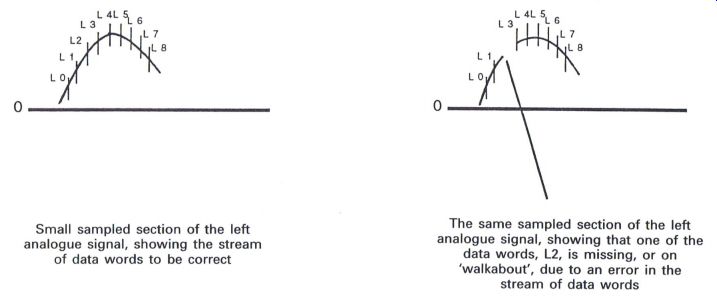
Figure 1.8 Comparison between correct and erroneous data stream
Small sampled section of the left analog signal, showing the stream of data words to be correct -----The same sampled section of the left analog signal, showing that one of the data words, L2, is missing, or on 'walkabout', due to an error in the stream of data words
--------
Again it would be logical to mute the sound output when an error has been identified, so that the recipient does not hear undesirable sounds. Un fortunately life rarely proves easy in the most logical of concepts.
Consider the sampled signal and the application of muting when the error occurs in Fig. 1.9.
If the portion of the analog waveform shown is the motion of the loudspeaker as it responds to the audio signal, then when the muting is applied, a bigger and better 'glitch' could occur, which would probably be even more undesirable than the original error if that had been allowed to be reproduced. In fact, history reveals that in the early design stages of CDs, when this form of error correction was applied at high output levels, the final effect proved detrimental to loudspeakers whereby the speech coil and the cone parted
Again it would be logical to mute the sound output when an error has been identified, so that the recipient does not hear undesirable sounds. Unfortunately life rarely proves easy in the most logical of concepts.
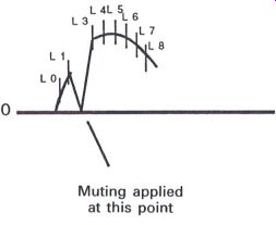
Figure 1.9 The effect of applying muting
Consider the sampled signal and the application of muting when the error occurs in Fig. 1.9.
If the portion of the analog waveform shown is the motion of the loudspeaker as it responds to the audio signal, t hen when the muting is applied, a bigger and better ' glitch' could occur , which would probably be even more undesirable than the or signal error if that had been allowed to be reproduced. In fact , history reveals that in the early design stages of CDs, when this form of error correction was applied at high output levels, the final effect proved detriment al to loudspeakers whereby the speech coil and the cone parted company quite effectively. However, muting does play its part in the error correction process, and is normally applied at the times when an extensive series of errors occurs and other methods prove unacceptable.
Previous word hold
Due to the large number of operations that take place when manipulating the digital information, whether when putting that information on to the disc, or during digital processing within the CD player, a substantial number of memory circuits are used, especially within the CD player itself.
In fact, as the audio data are being processed within the player, there is a period of time when all the digital audio information is sequentially held in memory for a brief period of time.
It could therefore be logical to replace a doubtful data word with the nearest one that is similar in value. When the original analog signal is sampled, and each sample turned into a 16 bit word, there are in fact 65 536 different combinations of the 16 bit code from all the 0's to all the 1's. Thus it is reasonable to accept that the data word preceding the error word could be approximately 1/65,000th different in level to the original correct data word. Again, as it is quite logical to assume that there is no person in existence who is capable of determining such differences in sound levels, then the previous word hold is an acceptable substitute (Fig. 1.10).
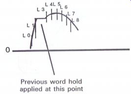
Figure 1.10 Previous word hold--- Previous word hold applied at this point
Linear interpolation
The previous word hold method of error correction can be fur t her improved with linear interpolation, where it is possible to compare the data word before the error word and the data word after the error word and, by taking the average of the sum of these two words and using this as the substitute for the error word, it is possible to achieve a more accurate assumption of the missing word (Fig. 1.11).
Interleaving
Interleaving is an extremely complex process and is complementary to the error correction process, where the basic operation is to ' jumble up' the audio data words on the CD in a defined arrangement , and to re-arrange those data words back int o their original order within the CD player before the process of restoring the digital data back int o the original analog information.
The interleaving process is achieved by inserting the data words into a series of delays. These delays are in multiples of one sampling period or data word in length, and are in the form of random access memory, from where they are initially stored and then extracted in a strictly defined sequence. This actually causes data words to be delayed by varying amounts, which in turn causes the data words to be effectively 'jumbled up' on the disc. Providing these data words are 'un-jumbled' within the CD player in the reverse manner, the data words will re-appear in the correct sequence.
Linear interpolation (L2 = the average of L1 + L3)
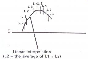
Figure 1.11 Linear
interpolation
Within the CD player this process is reversed through a series of delays which are set in the reverse order, and it is this operation that will effectively 'restructure' the data sequence back into the original order.
Control word
After the error correction and interleaving processes, it is now necessary to insert an extra 8 bit data word, which is referred to as the control word, or sub-code, with another multiplexer performing this task at regular and specific intervals (Fig. 1.13).
The purpose of the control word is to provide disc identification information, and each of the eight bits that comprise the control word has its own unique identification. As the data information is 'laid' along the track on the CD, the control word is inserted immediately before a group or block of audio data information, and immediately after a sync. word, the purpose of which is described at the end of this section.
As the disc rotates within the CD player, the control word is identified within the processing circuits of the player. Each bit, with its own identification, is inserted into a specific memory location, and the relevant memory location is analyzed at regular intervals to determine the data information that has 'built up' over a period of time, which is in effect after 98 control words have been stored.
Fig. 1.12 illustrates the basic concept of the interleaving process. During the recording pro cess the serial data words are turned int o parallel data words by the first serial to parallel converter , and then passed int o each delay with the result that the output will be the data words appearing at differing times. The parallel data words are t hen converted back int o serial data by the subsequent parallel to serial converter before eventually arriving on the CD.
Within the CD player this process is reversed through a series of delays which are set in the reverse order , and it is this operation that will effectively 'restructure the data sequence back into the original order.
Control word
After the error correction and interleaving processes, it is now necessary to insert an extra 8 bit data word, which is refer red to as the control word, or sub-code, with another multiplexer performing this task at regular and specific intervals (Fig. 1.13).
The purpose of the control word is to provide disc identification information, and each of the eight bit s that comprise the control word has it s own unique identification. As the data information is 'laid' along the track on the CD, the control word is inserted immediately before a group or block of audio data information, and immediately after a sync, word, the purpose of which is described at the end of this section .
As the disc rotates within the CD player , the control word is identified within the processing circuit s of the player . Each bit , with its own identification, is inserted int o a specific memory location, and the relevant memory location is analyzed at regular intervals to determine the data information that has ' built up' over a period of time, which is in effect after 98 control words have been stored.
----------------------
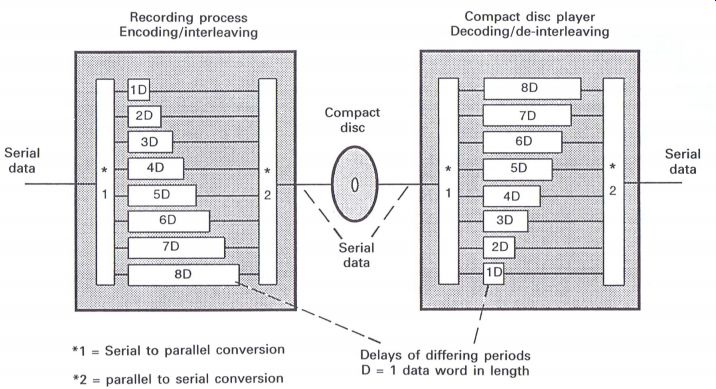
Figure 1.12-------Basic interleaving/de-interleaving process The basic
delay concept , where the serial data are turned int o parallel data, in
terms of blocks of data words. Each data word is delayed by differing amount
s during the recording process, and delayed again during the playback process.
However , providing the decoding is in effect the reverse of the encoding,
the original data word arrangement will be restored.
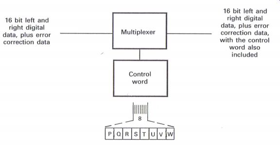
Figure 1.13--------The sound control word 16 bit left and right digital
data, plus error correction data 16 bit left and right digital data, plus
error correction data 16 bit left and right digital data, plus error correction
data, with the control word also included 16 bit left and right digital
data, plus error correction data, with the control word also included
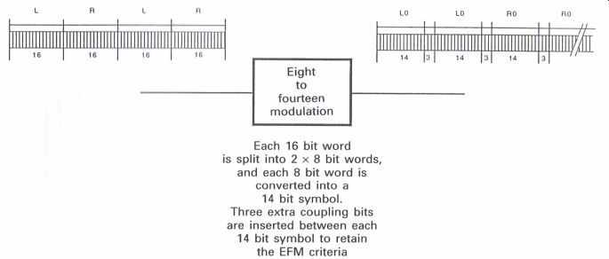
Figure 1.14, eight to fourteen modulation-------Each 16 bit word is split
into 2 x 8 bit words, and each 8 bit word is converted into a 14 bit symbol.
Three extra coupling bits are inserted between each 14 bit symbol to retain
the EFM criteria Each 16 bit word is split into 2 x 8 bit words, and each
8 bit word is converted into a 14 bit symbol. Three extra coupling bits
are inserted between each 14 bit symbol to retain the EFM criteria.
------------ ------------------------------
Only the P and Q bit s are in general use with CD players.
The R through to W bit s are in t ended for use with computer displays and the relevant software to display graphics, such as the words of the song being sung on the disc, a new concept of
'Sing-along a Max' (though not to be confused with Karaoke). The P bit is used to 'inform' the CD player that the music from the disc is about to commence, and enables the internal muting circuit s on some of the early CD players to be switched of f so that the analog information can be applied to the audio circuits. The later and more sophisticated players t end to release the mute circuits in relation to the availability of the data ready for audio processing.
The Q bit contains an extensive range of information including:
1 total playing time,
2 total number of music tracks,
3 individual music track identification,
4 elapsed playing time for each music track,
5 end of playing area information to enable the player to be stopped,
and 6 dc-emphasis information--a requirement by the recording authorities to be able to apply additional emphasis on any specific track and there fore enable the relative de-emphasis circuits to be switched in or out accordingly.
Oilier information can be available such as copyright, catalog number , as well as recording date and serial number , none of which is used within most domestic players currently available.
The total playing time and the total number of music tracks comprise the table of contents (TOC) information which all CD players are required to ‘know' before commencing to play a CD.
The control word is processed within the decoder section of the CD player .
Eight to fourteen modulation
After the process of interleaving the data, and after adding the control word, the next major operation is the technique of eight to fourteen modulation (EFM) (Fig. 1.14). Within this stage of operation during the recording processes onto CD, the 16 bit data words are changed int o two 8 bit data words, and each 8 bit data word is then changed into a 14-bit symbol. The term 'symbol' is used to differentiate e between a data word of 8 or 16 bits, and it s transformation into a 14 bit word or symbol.
To appreciate the reasons for the technique of EFM, it is useful to determine the problems that can occur when the data are actually put onto the CD, and therefore the basic process of disc manufacture is now worth considering.
Compact disc construction
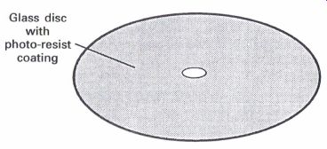
Figure 1.15 CD construction
When a CD is manufactured, a disc of glass, of extremely high precision, is coated with a photo resist material which is sensitive to laser light (Fig. 1.15). This glass disc is placed into the recording machinery at the time of manufacture to expose a fine helical track onto the photo-resist material, the width of the track being 0.5 um (Fig. 1.16).
The laser will expose the photo-resist surface with a 0.5 pm width spiral track as the disc rotates, commencing from the center and working towards the outer edge. The laser beam will be operated in relation to the data information, whereby the laser is switched on and off as the 1's information appears, creating a track of exposed photo-resist material that will comprise a series of dashes, the length of which and the intervals between which will be related to when the 1's occur. No 0's are recorded onto the disc; they are re-generated within the CD players.
Whenever a 1 occurs in the digital data, the laser beam, recording the information onto the photo-resist surface, will alternately switch ON and OFF as each 1 occurs, subsequently exposing the photo-resist surface of the disc and creating a series of 'dashes' 0.5 mm wide, the length being dependent on the period or distance between the 1's.
On completion of the recording process, the unexposed photo-resist material is chemically removed, leaving a helical track across the surface of the glass disc, which becomes the master to produce the inject ion-molding formers for the mass production of the result ant CD. The playing surface of a CD is a thin layer of a special injection-molded plastic material, which is indented from the non-playing side, with a series of ' pits' (Fig. 1.17).
The data stream shown to illustrate how a disc is manufactured 'conveniently' had no consecutive 1's in the data stream, but of course the digital data can comprise any combination of 0's and 1' s, and instances will frequently occur when there will be long series of 0' s or 1's (Figs 1.18 and 1.19).
When a series of 1's occurs (Fig. 1.18) the following problems can arise:
1 The frequency rate will increase.
2 The 'pit ' length may become too short , and may be shorter than the track width.
3 The high 1's rate can be integrated within the servo circuit s to create varying d.c. levels which can cause the servo circuit s to become unstable.
When a series of 0's occurs (Fig. 1.19) the following problems can arise:
1 Without any 1's occurring at regular intervals, the lock of the phase lock loop of the voltage cont rolled oscillator within the CD player decoder circuit can become unstable.
2 If a long series of 0's causes long distances between the pit s or bumps, the 'trackability' of the player can be affected due to long distances without any track being present.
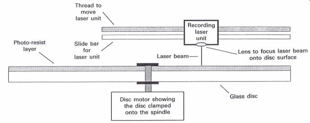
Figure 1.16 Basic mechanical arrangement for disc recording
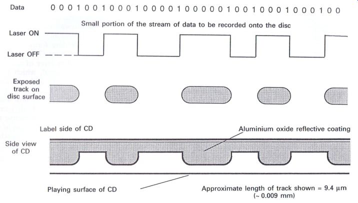
Figure 1.17 Enlarged side section view of CD, showing the 'pits' indented
into the back of the playing surface
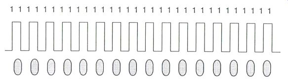
Figure 1.18 A long series of 1's
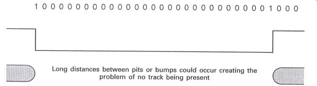
Figure 1.19 A long series of 0's Figure 1.
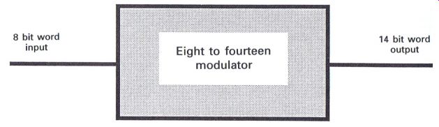
Figure 1.20 The EFM process
To overcome these problems the method of EFM was devised. It is purely a process of being able to effectively transfer the digital data onto the CD without any of the problems outlined above.
When a 16 bit word is prepared for the EFM process, the 16 bit word is split into two 8 bit words. This stage is easily achieved by taking the first 8 bits followed by the second 8 bits. Of the 8 bit sequence of data, there are 256 different combinations, from all the 0's
00000000 through to all the 1's.
1 1 1 1 1 1 1 1
With the 14 bit code there are 16,364 possible combinations from all the 0's
00000000000000 to all the 1's.
11111111111111
However, only 267 of these combinations satisfy certain criteria, which are: (1) that no two 1's are consecutive; (2) that a minimum of two 0's exist between two 1's; and (3) that a maximum of ten
0's exist between two 1's. Of the 267 combinations that fall into these criteria, 256 have been specifically selected, and put into a 'look-up' table. Each 8 bit combination is then 'paired' with a specific 14 bit code, of which three examples are:
00000010 = 10010000100000
01011001 = 10000000000100
11111100 = 01000000010010
The new 14 bit 'symbols' now represent the original data information when 'embodied' onto the CD, and when this information is retrieved from the disc within the CD player, another 'lookup' table will enable the 14 bit data to be transferred back into the original 8 bit code. Two 8 bit 'words' together will now comprise the original 16 bit word that was developed to begin with.
One trusts that this method of explanation will enable the 'light' to shine through reasonably brightly.
The eight to fourteen modulation process
Consider the following 16 bit word
0111101001111100 which is split into two 8 bit words
01111010 01111100 and fed into the eight to fourteen modulator where they are converted into two 14 bit symbols (Fig. 1.20):
10010000000010 01000000000010
Again consider the following 16 bit word 0111101001111100 split into two 8 bit words
01111010 01111100 and fed into the eight to fourteen modulator (Fig. 1.21).
The EFM criteria are as follows:
1 No two 1's will be consecutive.
2 The minimum spacing between two 1's will be two 0's.
3 The maximum spacing between two 1's will be ten 0's.
To overcome these problems the method of EFM was devised. It is purely a process of being able to effectively transfer the digital data onto the CD without any of the problems out lined above.
When a 16 bit word is prepared for the EFM process, the 16 bit word is split into two 8 bit words. This stage is easily achieved by taking the first 8 bit s followed by the second 8 bits. Of the 8 bit sequence of data, there are 256 different combinations, from all the 0's 00000000 through to all the 1's.
11111111
With the 14 bit code there are 16,364 possible combinations from all the 0's 00000000000000 to all the 1's.
11111111111111
However , only 267 of these combinations satisfy certain criteria, which are: (1) that no two 1's are consecutive; (2) that a minimum of two 0' s exist between two 1's; and (3) that a maximum of ten
0's exist between two 1's.
Of the 267 combinations that fall into these criteria, 256 have been specifically selected, and put into a 'look-up' table. Each 8 bit combination is t hen 'paired' with a specific 14 bit code, of which three examples are:
00000010 = 10010000100000
01011001 = 10000000000100 11111100 = 01000000010010
The new 14 bit 'symbols' now represent the original data information when ' embodied' onto the CD, and when this information is retrieved from the disc within the CD player , another 'look up 'table will enable the 14 bit data to be transferred back int o the original 8 bit code. Two 8 bit 'words' together will now comprise the original 16 bit word that was developed to begin with.
One trusts that this method of explanation will enable the ' light ' to shine through reasonably brightly.
The eight to fourteen modulation process
Consider the following 16 bit word
0111101001111100 which is split int o two 8 bit words
01111010 01111100 and fed int o the eight to fourteen modulator where t hey are converted into two 14 bit symbols (Fig. 1.20):
10010000000010 01000000000010
Again consider the following 16 bit word
0111101001111100 split int o two 8 bit words 01111010 01111100 and fed into the eight to fourteen modulator (Fig. 1.21) .
The EFM criteria are as follows:
1 No two 1's will be consecutive.
2 The minimum spacing between two 1's will be two 0's.
3 The maximum spacing between two 1's will be t en 0's.
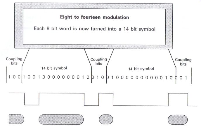
Figure 1.21 The EFM criteria
These criteria will ensure the following:
1 The frequency bandwidth is reduced.
2 The d.c. content is reduced.
3 The pit length is now wider than the track width.
4 With regular appearance of 1's, i.e. no more than ten 0's, the phase locked loop of the VCO in the decoder will remain locked.
5 Trackability across the surface of the disc will be maintained.
Coupling bits
From the above process, it can be observed that three extra bits have been inserted between each 14 bit 'symbol'; these are referred to as coupling bits. The purpose of these extra bits is to allow for the fact that throughout the EFM process, it could not be guaranteed that when one 14 bit symbol ended in a 1, the next 14 bit symbol would not commence in a 1, therefore disrupting the achievements to be gained with this process. The extra bits are inserted under 'computer control' by analyzing subsequent symbols in order that the relevant extra bits enable the required criteria to be maintained. In fact these extra bits are identified within the processing circuits of the CD player and then literally 'thrown away' as they fulfill no further function.
Pit lengths
As a result of the EFM process, there are only nine different 'pit' lengths to carry all the necessary digital data and information for effective CD player operation (Fig. 1.22). Reference is made in Fig. 1.23 to the final clock frequency of 4.3218 MHz, which is the final 'clock' rate for the data on CD, and will be referred to later. From this diagram it can be seen that the start and finish of any 'pit' length is related to the clock frequency of 4.3218 MHz, which is related to the VCO in the CD player, which normally operates at twice the Clock frequency (i.e. 4.3218 x 2 = 8.6436 MHz). Whilst a CD is in operation, and whilst all the different 'pit' lengths are continually appearing in relation to the digital data information, each 'pit' length will develop a subharmonic of the clock frequency.
These criteria will ensure the following:
1 The frequency bandwidth is reduced.
2 The d.c. content is reduced.
3 The pit length is now wider than the track width.
4 With regular appearance of 1's, i.e. no more than ten 0's, the phase locked loop of the VCO in the decoder will remain locked.
5 Trackability across the surface of the disc will be maintained.
Coupling bits
From the above process, it can be observed that three extra bits have been inserted between each 14 bit 'symbol'; these are refer red to as coupling bit s. The purpose of these extra bit s is to allow for the fact that throughout the EFM process, it could not be guaranteed that when one 14 bit symbol ended in a 1, the next 14 bit symbol would not commence in a 1, therefore disrupting the achievement s to be gained with this process. The extra bit s are inserted under ' computer control' by analyzing subsequent symbols in order that the relevant extra bit s enable the required criteria to be maintained. In fact these extra bit s are identified within the processing circuits of the CD player and t hen literally ' thrown away' as t hey fulfill no further function.
Pit lengths
As a result of the EFM process, there are only nine different ' pit lengths to carry all the necessary digital data and information for effective CD player operation (Fig. 1.22). Reference is made in Fig. 1.23 to the final clock frequency of 4.3218 MHz, which is the final 'clock' rate for the data on CD, and will be refer red to later. From this diagram it can be seen that the start and finish of any 'pit length is related to the clock frequency of 4.3218 MHz, which is related to the VCO in the CD player , which normally operates at twice the clock frequency (i.e. 4.3218 x 2 = 8.6436 MHz). Whilst a CD is in operation, and whilst all the different 'pit ' lengths are continually appearing in relation to the digital data information, each 'pit' length will develop a subharmonic of the clock frequency.
'Pits' are sequential along a helical track, and the reflected light from the laser beam varies when compared between a 'pit' and 'no pit' or space area. The start or finish of a 'pit' or 'space' indicates the 1's information, whilst the 0's are re-inserted in the decoder of the CD player
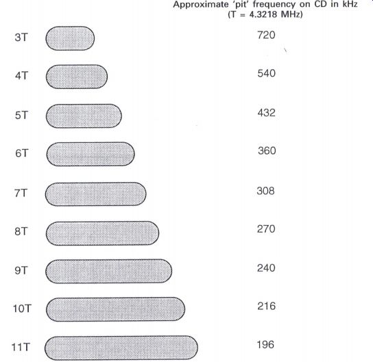
Figure 1.22 Comparison of the various pit lengths
Pits' are sequential along a helical track, and the reflected light from the laser beam varies when compared between a 'pit' and 'no pit ' or space area. The start or finish of a 'pit ' or 'space' indicates the 1's information, whilst the 0's are re-inserted in the decoder of the CD player
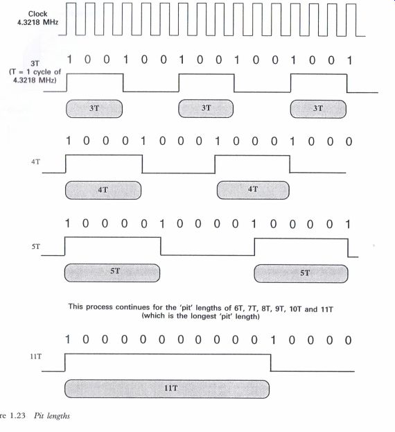
Figure 1.23 Pit lengths -------This process continues for the 'pit' lengths
of 6T, 7T, 8T, 9T, WT and 11T (which is the longest 'pit' length)
Sync. Word
The final information to be inserted in the recording sequence is the sync. word (Fig. 1.24), which is used in the CD player as the 'start point' for the data to commence the necessary processing, and also as a signal to be compared for the disc speed control circuits.
The sync. signal is uniquely different to all other data information on
CD, and comprises a 24 bit word as follows: 100000000001000000000010.
Fig. 1.25, showing how the track is laid down, will indicate how the data
are positioned within one frame.
The path of the original analog signal from its humble beginnings through to becoming an almost insignificant part of a 'pit' or 'bump', depending upon which way you are looking at the disc, or even the space between, has now been completed.
CD technology is a very complex process, and it often a wonder that the technology works as well as it does, especially when installed in a motor vehicle bumping along some of the 'better' highways.
Many engineers have been known to almost run the other way when it comes to CD player servicing, but with a reasonable amount of knowledge CD players do not constitute a major problem. Having considered some of the basic concepts of the CD, it is now worthwhile considering a typical CD player and its basic operation.
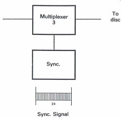
Figure 1.24 Sync. signal data positioning
------------
Frame information
One frame--588 bits Bit rate or disc clock frequency 4.3218 MHz Frame or sync. word frequency--7.35 RM:
(7.35 kHz--4.3218 MHz divided by 588)
--------------
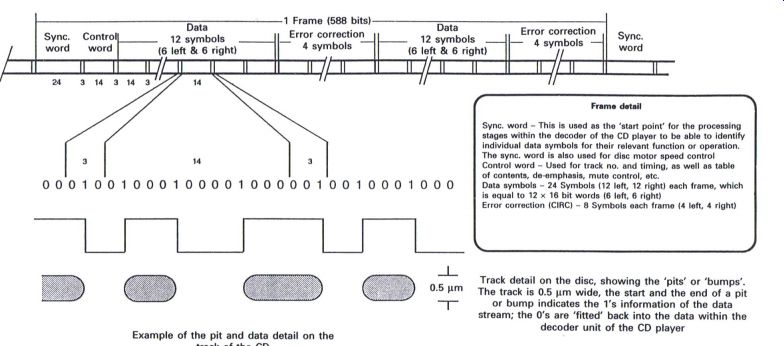
Figure 1.25 Basic CD system track detail
Frame detail
Sync. word--This Is used as the 'start point' for the processing stages within the decoder of the CD player to be able to Identify
The sync. word Is also used for disc motor speed control
Control word--Used for track no. and timing, as well as table at contents, de-emphasis, mute control, etc.
Data symbols--24 Symbols (12 left, 12 right) each frame. which Is equal to 12 x 16 bit words (8 left, 6 right)
Error correction (CIRC)--8 Symbols each frame (4 left, 4 right)
Track detail on the disc, showing the 'pits' or 'bumps'.
The track is 0.5 pm wide, the start and the end of a pit or bump indicates the 1's information of the data stream; the 0's are 'fitted' back into the data within the decoder unit of the CD player
Example of the pit and data detail on the track of the CD
--------------