The main function of a CD player is to play the CD at the relevant speed and retrieve the digital data from the disc by means of a reflected laser beam, converting the digital data back into the original analog form as accurately as possible (Fig. 2.1).
Much of a CD player will comprise various servo systems that will enable the laser beam to be accurately focused onto the surface of the disc and simultaneously track the laser beam across the surface of the disc, whilst it is rotated at the correct speed (Fig. 2.1). All CD players are required to operate in a specific manner, the sequence of which is controlled by some form of system control.
Most of the electronic operations take place within large-scale integrated circuits, which despite their complexity are usually extremely reliable.
Mechanical operations are relatively simple and are limited to motors to drive the disc, optical assembly and the loading and unloading mechanism, and a pair of coils which will enable the lens within the optical assembly to move vertically and laterally. An exception to this is the Philips radial system, where the lens moves only vertically, and where the complete optical assembly moves radially in a similar manner to the moving coil meter.
Optical assembly
The optical assembly is probably one of the most important blocks within the CD player, and there are numerous different designs. A fundamental description of some of the typical optical blocks that are generally available is given in Section 3.
Generally there are two main types of optical block:
1. The Philips or radial optical assembly. This unit will be found in the Philips and Marantz players, as well as Denon, occasionally Sharp and Technics, and some other players such as Binatone and Sentra.
2. The Japanese tangential tracking type, the alternative, appears in all other players, ranging from Aiwa, Akai, Hitachi, Kenwood, through to Pioneer and Sony, plus all other manufacturers in between, and possibly beyond.
Contained within this unit will be the laser diode to produce a laser beam that is reflected from the surface of the CD through certain components within the block onto a photo-diode array which will produce a range of signals that are in fact the effect of reflected light variations from the 'pit' or 'bump' information on the playing surface of the CD, which in turn become the current variations from the photo-diodes contained within the photo diode array.
Suffice to say at this stage, these current variations will in due course produce a range of signals that will represent the music information or data from the disc, together with focus, tracking, and spindle or disc speed information that will enable the disc to be played in the correct manner.
Linked to the optical assembly is the automatic power control block which will enable the laser power to be controlled as required, as well as enabling it to be maintained at a constant power level.
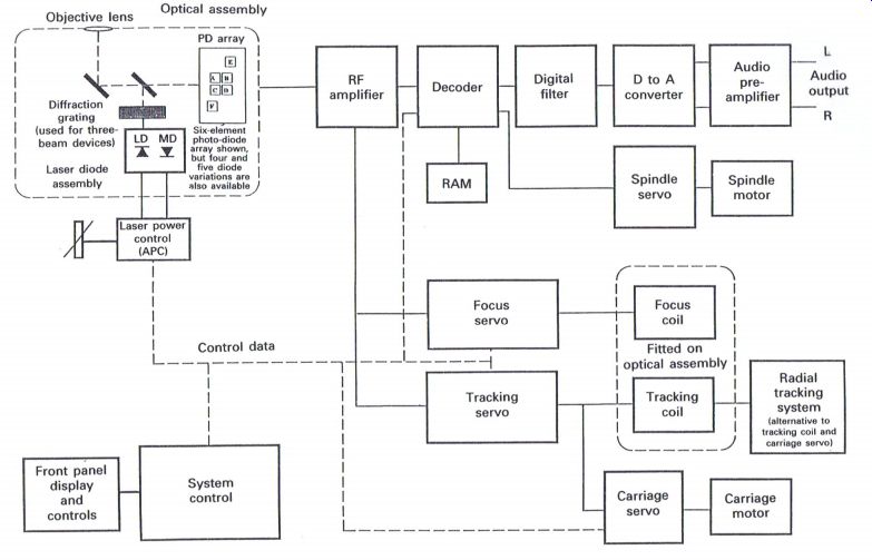
Figure 2.1 Basic block diagram of a CD player
RF amplifier
The current variation signals from the photo-diode array within the optical block are passed to the RF amplifier (Fig. 2.2), where the necessary processing takes place to produce the required information, such as data, focus and tracking which will be passed onto their relevant operating sections.
Other signals are also produced which are de tailed in the signal processing circuits Within the RF amplifier.
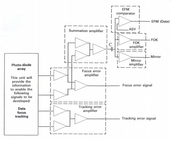
Figure 2.2 RF amplifier
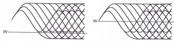
Figure 2.3 RF eye pattern waveforms
RF amplifier: signal processing
The signals from the photo-diode (PD) array, which usually comprises either four or six photodiodes, are processed to produce three basic signals: the data from the disc, the focus and the tracking signals. The basic circuit illustrated in Fig. 2.2 is normally contained within an integrated circuit, with the relevant outputs as indicated.
Focus error amplifier
This circuit amplifies the signals from four of the photo-diodes which will relate to focus information, and then the signals are passed to a differential amplifier to provide the focus error output, the value and polarity of which will be related to the amount and direction of focus error.
When the in-focus situation is achieved, the focus error signal will be zero, but when mis-focus occurs, then depending upon the direction in which the out of focus situation arises, the polarity of the signal will be either positive or negative with respect to zero, and the amount or level of the signal will relate to the extent of the mis-focus.
Tracking error amplifier
The outputs from either a special pair of photodiodes, or possibly four photo-diodes, are used for tracking purposes only, and as the CD rotates, the helical track on the disc will cause different amounts of reflectivity from the surface of the disc. This in turn will develop an output from the differential amplifier which produces the tracking error signal, a signal or voltage, the value and polarity of which will be related to the amount and direction of tracking error, or in the case of the radial optical assembly, the radial error signal.
Summation amplifier
The input to this amplifier comprises the output from four photo-diodes. These signals are summed or added together within this amplifier to produce an output that will be passed on to the decoder. This signal is usually referred to as the RF signal or eye pattern waveform (Fig. 2.3) and comprises the data information from the CD that is to be further processed in order that the original analog audio information may be obtained.
The information relating to disc speed can also be obtained from this signal. The output from this amplifier is fed via a capacitor, C, to three more circuits. The purpose of the capacitor is twofold: firstly, to isolate any d.c. content from the summation amplifier and to produce an RF output signal, comprising frequencies within the range 196-720 kHz with the level varying either side of zero depending upon the reflectivity of the laser beam from the playing surface of the CD. Secondly, the waveforms resulting from the reflected signals from the disc do not tend to be symmetrical due to variations during disc manufacture, as well as the actual shape of the 'pits' or 'bumps' on the disc. Here the capacitor will tend to ensure that the waveform is reasonably symmetrical either side of the zero line, and there fore a waveform effectively crossing the zero line can indicate that a '1' is present within the data stream.
Good quality 'pits' or 'bumps' with sharply defined edges
Poor quality 'pits' or 'bumps' with rounded edges causing the 1's content to be poorly defined
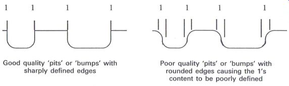
Figure 2.4 Comparison of good and poor quality 'pits' or 'bumps'
The RF or eye pattern waveform is characteristic of any CD player and virtually any type of CD.
The period lengths are related to the differing lengths of the 'pits' or 'bumps' on the playing surface of the disc, which in turn are related to the final clock frequency as a result of all the various processing of the data that takes place prior to the recording of the data onto the CD. The shortest period in the above waveforms is the result of the shortest 'pit' length or space between 'pits', and is equivalent to three cycles of the final clock frequency of 4.3218 MHz. Each period length thereafter is equal to the next 'pit' length and therefore a further cycle of the final clock frequency.
EFM comparator
The RF signal from the capacitor is now passed to the EFM comparator, where it is effectively amplified to provide a square wave output with clean or steep leading and trailing edges. It is extremely important to obtain as square an output as possible as the leading and trailing edges will indicate when a '1' occurs within the data stream.
In the injection mold or 'pressing' stage of the manufacturing process of the CD, variations in quality can occur during the lifetime of a specific mold as it begins to wear with each successive 'pressing', causing the edges of the 'pits' or 'bumps' to become less defined. This can result in problems within the CD player of identifying where a 'pit' starts or commences, and thus impairs its ability to produce a '1' at the correct point in time (Fig. 2.4).
The EFM comparator within most CD players will have two inputs, one being the RF signal, and the other being the ASY (asymmetry) voltage or reference voltage. The latter is related to the timing of the EFM, or squared RF signal waveform, compared with a phase locked clock (PLCK) within the decoder, which after filtering, produces a reference voltage (ASY) for the EFM comparator to operate. The resultant output from the comparator is now passed to the decoder for further processing, to eventually enable the required 16 bit data words to be obtained for conversion back into their original analog counterparts.
FOK amplifier
When a CD is inserted into the player, it is necessary for the focus servo to initially operate the objective lens to achieve focus onto the playing surface of the disc. This is achieved by causing the lens to elevate up and down usually two or three times. When focus has been achieved, which is related to a maximum RF signal from the disc, 3 HIGH output will be obtained from the FOK (focus OK) amplifier, which in turn communicates to the relevant control circuits that focus has been achieved.
In many players the FOK signal is also used to inform the control circuits of the player that a disc is present and ready for playing.
Mirror amplifier
The tracking servo enables the laser beam to gradually move across the playing surface of the CD by a combination of moving the objective sideways as well as physically moving the complete optical assembly.
It is possible for the servo to allow the laser beam to track between the tracks containing the digital information, and therefore it is essential for the tracking servo to 'know' that it is tracking correctly along the data track.
The mirror signal enables the control circuits to be aware that incorrect tracking may be occurring, and this is determined by the fact that this signal will be LOW when actually 'on track' and
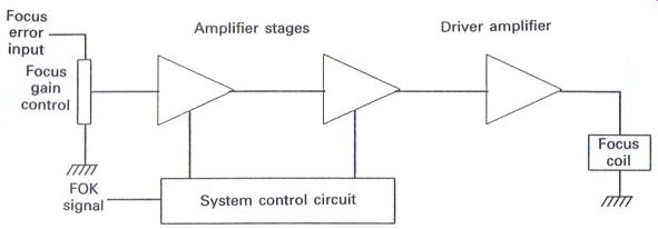
Figure 2.5 Focus servo HIGH when 'off track'. If this signal stays HIGH
beyond a defined period of time, the control circuit will effectively give
the tracking servo a 'kick' until the mirror signal maintains a LOW level,
thereby indicating an 'on-track' condition. The mirror signal is also used
whilst track jumping takes place when a new music track on the disc is
selected by the operator. The start of the required music track is computed
within the player whilst the optical assembly traverses across the disc
simultaneously counting individual tracks as they are crossed.
Servo circuits
Within most CD players there are usually four individual servo systems, but with the radial optical assembly only three servo systems will be present, i.e. the focus, radial and spindle servos:
Focus servo--to maintain the laser beam 'in focus' on the playing surface of the CD, by the vertical movement of the objective lens.
Tracking servo--to enable the laser beam to track across the playing surface of the CD by the sideways movement of the objective lens.
Carriage servo--to fractionally move the optical assembly when the objective lens begins to reach the limits of its operation. This servo works in conjunction with the tracking servo, and is often described as either the sled servo or slider servo.
Radial servo--with the radial optical assembly, this servo will take the place of the tracking and carriage servos. As the complete assembly is required to traverse radially across the surface of the disc in extremely fine movements measuring fractions of a micrometer, a wobble frequency is generated to overcome any 'stiction', a term relating to friction within servo systems, enabling a relatively large device to move in an extremely smooth manner.
Spindle servo--the speed of the disc is related to the position of the laser beam, and therefore the optical assembly, as it obtains the data information from the CD. The data rate from the CD is compared to an internal reference within the CD player, usually a crystal frequency source for stability, with a resultant signal to enable the CD to rotate at the correct speed, which is in the region of 500 rpm at the center or start of the disc, decreasing to around 180 rpm at the end of a 12 cm CD. As the data are processed within the decoder, the 16 bit data words are briefly stored into a random access memory (RAM), and then taken out of the memory as required. This operation is linked to the crystal clock that drives the disc at the approximately correct speed. As the data are removed from the memory, the disc speed will increase and decrease to continually maintain a certain amount of data within the RAM. This servo is frequently referred to as the disc servo or occasionally as the turntable servo.
Focus servo
The focus servo (Fig. 2.5) amplifies the focus error signal and applies the signals to the focus coil which is attached to the objective lens to enable it to move vertically and maintain focus on the playing surface of the CD.
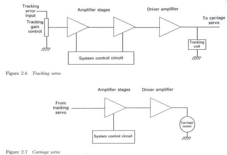
Figure 2.6 Tracking servo
The system control circuit controls the operation of the servo, ensuring that it operates at the correct time, usually after the laser has been switched on. The first operation is to cause the lens to move vertically in order to search for the correct focal point. Having achieved this, and
Figure 2.7 Carriage servo when the FOK signal has been received, the servo will then be allowed to operate normally, maintaining the required 'in-focus' condition. During the focus search sequence the first amplifier stage is normally switched off to prevent the developing focus error signal from counteracting the search operation.
Tracking servo
The tracking servo (Fig. 2.6) has many similarities to the focus servo, but its function is to enable the tracking error signal to be amplified and passed to the tracking coil, which in turn is attached to the objective lens to enable the relevant sideways movement to maintain the tracking requirement across the playing surface of the CD.
The objective lens has only a limited amount of lateral or sideways movement (approximately 2 mm) but as the movement increases laterally this can be interpreted as an increasing output from the tracking circuit which can be used to drive the carriage servo when necessary.
Again, the system control circuits control the operation of the tracking servo, enabling the servo to commence the tracking function when the CD is rotating, which on many players commences after the laser has been switched on and the focus servo has in turn commenced its own operation.
Carriage servo
The function of the carriage servo (Fig. 2.7) is to gradually move the optical assembly across the surface of the CD by driving the carriage motor, which in turn is mechanically connected via a long threaded drive to the optical assembly.
The gearing ratio is extremely high, which means that it can take up to 75 min, depending on the playing time of the CD, to enable the optical assembly to cover the playing area of the disc which can be in the region of 4.5 cm.
As the objective lens moves laterally (up to approximately 1 mm of movement) in conjunction with the tracking servo, the increasing signal to the tracking coil is passed to the carriage servo where it is amplified. When the output voltage
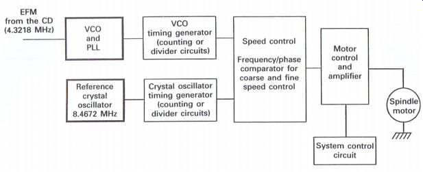
Figure 2.8 Basic spindle or disc motor servo system has reached a level
sufficient to operate the carriage motor, the motor will operate to move
the optical assembly a very small amount. Simultaneously the objective
lens will centralize its position again, with a resultant decrease in the
signal to the tracking coil stopping the carriage motor, until the level
has increased again to repeat the process. This procedure will continue
until the disc has completed the playing sequence.
Some CD players utilize a linear drive motor system instead of a conventional motor, with a similar if not more complicated operating process. Again the servo is controlled by the system control circuit, which allows the carriage servo to come into operation when the tracking servo is functioning. Signals can also be developed from the control circuit which will drive the motor during track location sequences when searching for selected music tracks on the disc, as well as returning the optical assembly back to the center or start position on completion of playing the CD, in readiness for playing another.
Spindle or disc motor servo
The spindle or disc motor ('spindle motor' will be used here for continuity) is required to rotate the disc at a speed that will maintain the surface speed of the disc passing the laser beam at a constant rate, which will be in the region of 1.21.4 m s". In effect this will mean that for a 12 cm disc, the actual rotation speed of the disc will commence at the center or start at around 500 rpm, slowing down to somewhere in the region of 200 rpm towards the outer edge of the disc.
During the sequence of enabling a player to actually play the disc, the spindle motor will 'kick start' usually after the laser and focus stages have operated correctly, with the system control circuit applying a control data signal to the motor control which enables the motor to start running up in speed.
A reference crystal frequency oscillator (8.4672 MHZ) will provide, via the timing generator, a crystal locked frequency to the input of the frequency (coarse) and phase (fine) speed control stage (Fig. 2.8).
As the spindle motor increases in speed, the EFM signal will appear as an increasing frequency which is applied to the voltage controlled oscillator (VCO) and phase locked loop (PLL) stage, which will enable an output of 4.3218 MHz to be applied to the VCO timing generator stage.
When the disc rotation approaches the correct (coarse) speed, the two frequency inputs to the speed control stage will be within a certain tolerance, which will provide an output to the motor control to override the 'kick start' voltage. The complete circuit will now take overall control and maintain the speed of the compact disc to provide an EFM output that will be in the general region of 4.3218 MHz, and after further processing in the decoder stage, the resultant data will be stored in the RAM for further processing.
It will be apparent that the disc speed will not, and indeed cannot, be maintained at an absolute surface speed of 1.2-1.4 m s", due to the requirement of continually reducing the disc speed as the disc is being played, and there is in fact fairly excessive 'wow' and 'flutter', which is corrected by the 'clocking' of the data through
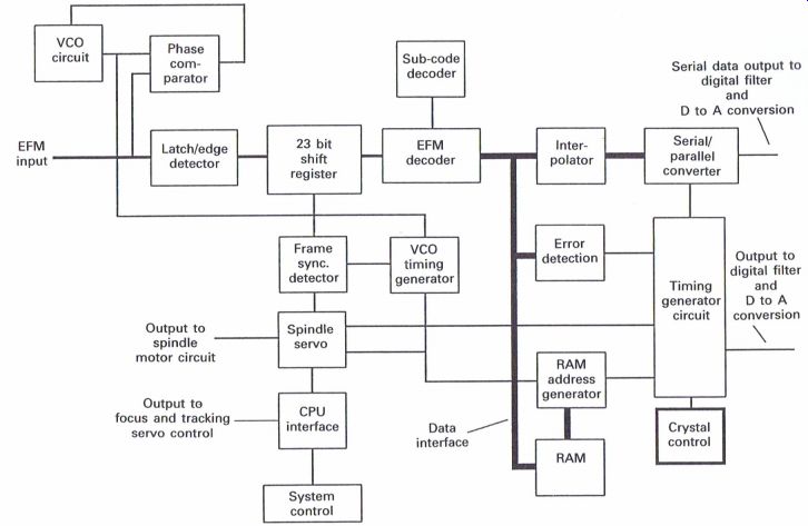
Figure 2.9 Basic decoder the RAM by a crystal reference source, within
the operation of the decoder.
The decoder
Much of the spindle servo circuitry is usually contained within the decoder, but despite its apparently small size as a component within the CD player (usually about the size of a standard postage stamp), it is fair to say that the decoder does quite a lot of work, with the support of a small amount of external circuitry. Fig. 2.9 illustrates the main features of the decoder section of a CD player.
Once the data from the disc have been initially processed from the original 'pits' or 'bumps', the data are now identified as the EFM signal and thus become the input to the decoder. Amongst the many processes that now take place, this signal is used to phase lock 3 VCO, usually operating at 8.64 MHZ, twice the effective CD clock frequency, the sync. signal is removed within the 23 bit shift register, and passed to the frame sync. circuits, with the main bulk of the data now passing to the EFM demodulator. Within the EFM demodulator, the 14 bit symbols are now restored back into their original 8 bit counterparts, with the three coupling bits being virtually discarded. With the exception of the 8 bit control word, the remaining 8 bit data words are now paired together to form the original 16 bit data words that are in effect the digital samples of the original analog information, but in a 'jumbled up' condition as a result of the interleaving process.
De-interleaving takes place with the use of the RAM, with error correction being applied using interpolation and relevant substitutions from the RAM as applicable, resulting from the error correction information contained within the cyclic redundancy check code (CRCC) data from the disc. The 8 bit control word is detected by the sub-code detector, with the P and Q bits being utilized accordingly.
System control plays its own part in the operation of the CD player by 'kick starting' the
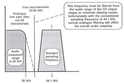
Figure 2.10 Problems with conventional sampling at PS = 4.41 kHz disc
and analyzing the fact that data are being retrieved from the disc. If
any errors are being detected the system control will make decisions as
to the type of correction to be applied, and if too many errors occur will,
in due course, stop the operation of the player. An interface is also present
to link up to the focus and tracking servos to ensure their correct operation.
The final digital data for processing into analog can be either in serial or parallel form; serial data being the normal requirement for domestic CD players, usually fed in modern players to a digital filter for the next stage of processing.
The complete decoder operation is strictly controlled by the crystal control circuit which acts as a master reference for the majority of the decoder functions.
Digital filtering and digital to analog conversion
When the digital data have been converted back into the original analog form, it is necessary to pass the analog signals through a filter network to remove any effects of the sampling frequency (44.1 kHz), which would appear as interference in the form of aliasing noise in the analog output circuits. In order that the effects of the interference are minimized it is essential to ensure that the first subharmonic of the sampling frequency (22.05 kHz) is removed, which will ensure that any effects from 44.1 kHz will be minimal. However, the filter cut-off characteristics must operate from 20 kHz to 22.05 kHz, a cut-off rate which is not possible with conventional inductive, capacitive, resistive types of filters without degrading the analog top end frequency response, which was a problem with the earlier CD players (Fig. 2.10).
Many developments have occurred within CD players with respect to improvements in the digital to analog conversion and filtering stages, and whilst filtering is an area to be improved, it is worthwhile considering the restructuring of the analog information from the digital data from the CD.
As seen in Fig. 2.11, another problem occurs with respect to quantization noise, whereby noise pulses can occur at the sampling points, which though at 44.1 kHz can still cause effects to decrease the signal to noise ratio of the CD player.
A method of overcoming both of these problems, i.e. the reduction in the high frequency response in order to overcome aliasing noise and the effect of quantization noise, is to introduce the technique of oversampling. But it must be remembered that the digital data on the CD are effectively 16 bit data words at the sampling frequency of 44.1 kHz and therefore cannot be altered, whereas techniques within the CD player can.
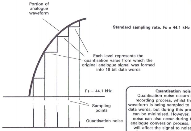
Figure 2.11 Restructuring the original analog info.
-------------
Standard sampling rate, Fs = 44.1 kHz
Each level represents the quantization value from which the original analog signal was formed into 16 bit data words
Quantization noise
Quantization noise occurs during the recording process, whilst the analog waveform is being sampled to produce 16 bit data words, but during this process the effect can be minimized. However, quantization noise can also occur during the digital to analog conversion process, which in turn Will affect the signal to noise ratio of an audio system. This effect can be reduced by using the technique of oversampling
------------
By the use of additional memory, delaying and multiplication techniques, it is possible to make acceptable predictions of a data word that can be included between any two of the sampling points described in Fig. 2.11.
A simple method of describing the achievement of an additional data word which can be effectively 'fitted in between' two original samples is by interpolation, i.e. adding two consecutive data words together, dividing by two and fitting the result in between the two original samples. Two important factors emerge from this concept:
(1) the sampling frequency must double in frequency to 88.2 kHz, and (2) quantization noise will reduce, thereby improving the signal to noise ratio.
The effective doubling of the sampling frequency ensures that a conventional filter can be used to remove the first subharmonic, which is now 44.1 kHz, with the effect of improving the high frequency response of the CD player.
Figs 2.12 and 2.13 illustrate the effect of two times and four times oversampling techniques, though many players utilize even higher sampling frequencies, especially in the realms of bit stream digital to analog methods which will be highlighted later.
The frequency response of the filtering circuits in the output stages is illustrated in Fig. 2.14 where a new sampling frequency of four times the standard used on the CD, i.e. 176.4 kHz, enables a more conventional filter to be designed, with less steep characteristics.
Digital filtering
The increases in the sampling frequencies can be achieved by multiplication and delaying techniques, as illustrated in Fig. 2.15. From this figure it may be appreciated that with the concept of four times oversampling it is possible to produce three digitally produced extra data words, which are in fact predictions, to be inserted between any two actual samples from the CD.
With the technique of delaying the original 16 bit data words, and then multiplying each result ant word four times, each multiplication being a different coefficient, a resultant series of 28 bit words is produced.
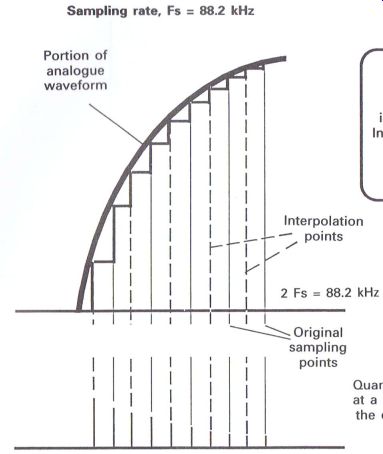
Figure 2.12 Two times oversampling
-----------------
Interpolation
Interpolation occurs when the average of two successive data words is inserted between those two data words.
In practice interpolation takes place within the digital filter of a CD player, where improved interpolation is achieved by analyzing a series of data words
Quantization noise is now at a higher frequency and the overall level has also reduced
-----------------
Summing a complete sequence or group of these resultant 28 bit words produces a weighted average of a large number of samples.
Whilst this description relates to four times oversampling, further improvements can be achieved using eight times oversampling, where the sampling frequency becomes 352.8 kHz. The resultant 28 bit data words are now passed on to noise shaping circuits where further improvements in the signal to noise ratio can be achieved.
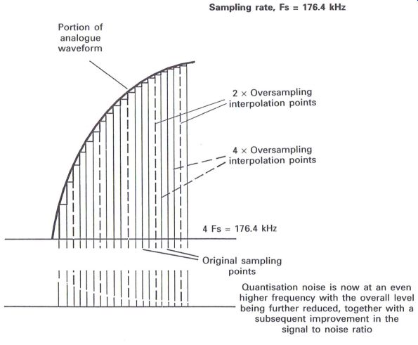
Figure 2.13 Four times oversampling
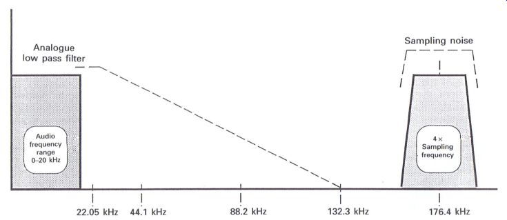
Figure 2.14 The improved filtering effects with four times oversampling
-------Quantization noise is now at an even higher frequency with the overall
level being further reduced, together with a subsequent improvement in
the signal to noise ratio
Noise shaping
The circuit shown in Fig. 2.16 can be used to improve the signal to noise ratio by utilizing the fact that the noise level of the signal will be contained within the least significant bit area. By extracting the 12 least significant bits, delaying them by one sampling period and then subtracting the resultant from the input signal, the output will now comprise the 16 most significant bits.
Fig. 2.16 provides an example of this concept, and can be identified as a single integration type of noise shaping circuit. More complex types are available comprising double integration or even multi-stage noise shaping (MASH) Circuits, all of which are progressions in the evolution, by various manufacturers, of the processing of the original 16 bit data words coming from the CD, the basic concept of which will covered at a later stage.
The 16 bit data words from the circuit shown in Fig. 2.16 can now be passed to the digital to analog converter for conversion back into the original analog information.
Digital to analog conversion
The 16 bit data words are passed to the D to A converter where the data information in terms of 0's and 1's will control internal switches to enable a current to be produced that ideally relates to the original analog value of the signal when it was first recorded onto CD.
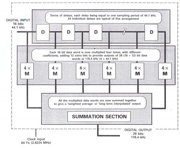
Figure 2.15 Digital filtering
The simplified diagram in Fig. 2.17 illustrates a series of current generators, each of which provides a current that is equal to half of the current provided by its left-hand counterpart. The left-hand current generator will provide half of the total value of current available.
The 16 bit data word is passed into the circuit, and whenever a 1 occurs within the word, the relevant switch b1-b16 will close. The sum of the currents related to when the 1's occur will pass to the current to voltage converter to provide an output that should be equivalent to the original analog value at the moment of sampling or quantization during the recording process.
Each subsequent data word will therefore en able the original analog signal to be sequentially restructured, and therefore the speed of operation is related to the sampling frequency of the data words being applied. However, D to A converters suffer from inherent problems which can cause discrepancies in the output signal in the form of non-linearity errors, zero cross distortion and glitches.
Non-linearity errors
Each current generator is usually formed by a resistive network to enable a specific current to flow, and it is essential for each generator to be a specific fraction of the one next to it. Thus if the MSB current generator is designed to provide half of the total current required, then the next generator must provide half of that value and so forth. Any variations of these tolerances will not enable a faithful reproduction of the original analog signal to be achieved.
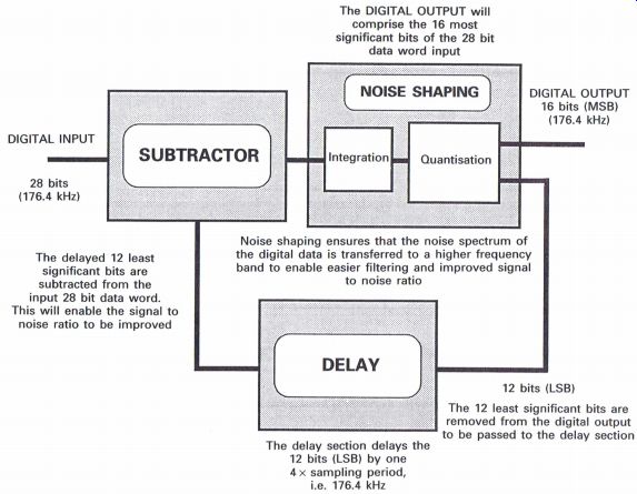
Figure 2.16 Noise shaping
Zero cross distortion
When the analog signal is operating within its positive half cycle the 16 bit digital data will be the complement of its opposite negative value, so as the analog signal traverses the zero cross point the sequence of bits will be reversed. The MSB during the positive half cycle is always a 0, whilst during the negative half cycle the MSB will always be a 1. Therefore with low level signals and any non-linearity within the LSB area of the D to A converter, distortion of the signal output can be caused.
Glitches
Glitches are caused when any of the switches do not operate at the precise moment of the occurrence of each relevant bit, with the result that an incorrect output can be momentarily obtained.
To overcome some of these problems, 18 bit and 20 bit D to A converters have been designed which enable a more faithful replication of the original signal to be achieved. The 18 or 20 bit data words can be derived from the digital filtering or oversampling process, but whether it be a 16, 18 or even 20 bit D to A converter, accurate manufacture of these items for the domestic CD player can prove extremely expensive.
Another method of digital to analog conversion proving to be extremely popular with modern players is the bitstream or one-bit system.
As previously mentioned, there has been a gradual evolution, by various manufacturers, regarding the processing of the digital data back into their original analog form as accurately as possible, and noise shaping is an essential prerequisite.
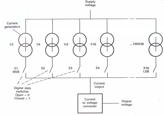
Figure 2.17 A series of current generators
Multi-stage noise shaping
As an example, the digital input from the digital filter can be in the form of a series of 28 bit data words at a sampling frequency of four or even eight times the original sampling frequency (i.e. 8Fs = 8 x 44.1 kHz = 352.8 kHz); this implies that there are either three or seven interpolated samples between any two data words from the CD. The MASH (Fig. 2.18) will now process the digital input at a much higher rate, in the order of 32 times the original sampling frequency (i.e. 32Fs = 44.1 kHz x 32 = 1.411 MHz), though some players use higher rates, and it would appear at this stage that the sampling frequencies are becoming inordinately high when compared to the original sampling frequency. In order that these increased sampling frequencies may be processed, it is necessary to use high clock frequencies which are obtained from a crystal oscillator.
But the implication now is that at 32Fs there must be 31 interpolated samples between any two data words from the disc. As a result, it is now not necessary to maintain such a high number of bits in each data word. In fact the output from the MASH circuit above is in the form of four bits, which will provide sufficient detail to effectively indicate the analog content in due course.
The 4 bit output is now passed to a pulse width modulator; 11 of the possible 4 bit combinations are used to provide 11 different pulse Widths, and the width of these pulses is related to the analog information. By passing these varying pulse widths to a low pass filter, or integrator, the required analog output will be obtained.
The resultant 4 bit data words basically represent the 'trend' of the signal between two original sampling points, and therefore a series of 16 bit or more data words becomes unnecessary. Only 1 1 different 4 bit data words are passed to a pulse-width modulator (Fig. 2.19) where each 4 bit word is converted into a single pulse each of a different width.
Figure 2.18 Multi-stage noise shaping
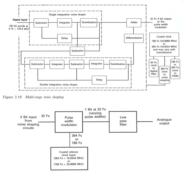
Figure 2.19 Pulse width modulation
This is where the term '1 bit digital to analog conversion' has caused confusion, as the question that has often been raised is: 'How can a 16 bit word become a 1 bit word?' Possibly the best way to accept this concept is to consider any one of the 11 different pulse widths, which now represents a small sample of the extra interpolated information between two original 16 bit data words from the disc, as a bit of information, and not necessarily as 1 bit of data.
Whilst a high clock frequency is used, timing circuits will provide the relevant clock frequencies for the different related circuits, which must be 'locked' to the same reference source. The output from the pulse width modulator is described as 1 bit information insomuch that it is a series of single pulses, the width of which is varying (up to 11 different widths), and it is therefore no longer a stream of data.
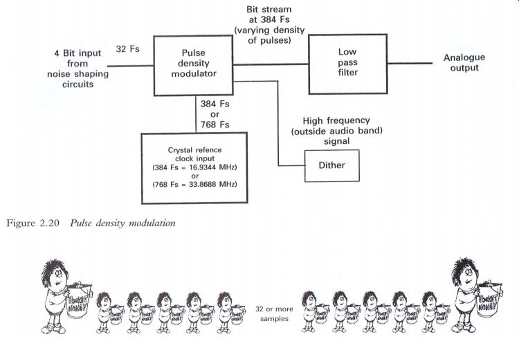
Figure 2.20 Pulse density modulation
--- Figure 2.21 One bit or bit stream D to A -- a pictorial analogy
One sample at 1 F3 (44.1 kHz) The little boy wants a lot more pocket money, but his father says...
'Not all at once'
So over period of time the little boy collects small amounts, until some while later (i.e. the next sampling point) he has got what he wants.
The principle of one bit, or bit stream D to A, is in effect smaller but varying faster samples between two sample points until the next sample point is reached.
The bucket could in fact contain water which has to be transferred from place to another, money but if the bucket was very heavy to carry, a lot of little boys could carry smaller varying amounts more quickly from one place to another. The actual individual amounts do not matter, as the accuracy is maintained from one sample point to the next. Each small bucket represents one
Net sample at 1 F5 (44.1 kHz) The little boy has got more pocket bit or portion of the original amount
-----------------
Passing the information through a low pass filter will enable the original analog information to be retrieved with much greater accuracy and simplicity compared to the more conventional method of D to A conversion, and therefore the problems of non-linearity, zero cross distortion and glitches are resolved. There is, however, one main problem with this method and that is 'jitter'.
Jitter is related to the accuracy of the actual start and finishing points of each pulse width, which can affect the final sound quality. This effect may be more apparent by using the higher clock frequency of 786 Fs, and to endeavor to overcome this problem some players may use the lower clock frequency of 384 F3.
Another method of resolving the problem of jitter is to fill the varying pulse widths with the high clock frequency pulses, with the final result becoming a continuous stream of bits (hence the term 'bit-stream'). Passing these bits through the low pass filter produces the same analogue output. This method was originally used by Philips, but has now become a standard feature of many other types of CD player. However, this method can create other problems, and when zero or low level signal levels occur, it is possible to hear spurious noises resulting from the 'idling' of the data that will occur at these levels. This can be overcome by applying a high out of audio range 'dither' signal to the circuit. This will remove the spurious noises, without affecting the final integration of the bit stream information in the low pass filter.
With the pulse density concept (Fig. 2.20) the circuit arrangement is virtually identical, the main difference being that instead of producing varying pulse widths, suffering from possible jitter, a stream of 384 F3 pulses is used, the number or density of which will relate to the original analog output from the low pass filter. The pulse density modulation or bit stream principle is virtually the latest technology being utilized within CD technology and the foregoing descriptions are intended to provide an overall appreciation of some of the technologies involved.
--------------