The optical assembly, or pick-up unit, is one of the most important components within a CD player, and is essential to being able to determine the data or music information that has been recorded on to the CD.
Though optical assemblies from different manufacturers will vary, they will contain similar elements which will basically include:
1. a low power laser to illuminate the disc track;
2. a lens and prism system to direct the laser beam towards the disc surface, and the reflected beam towards the photo-diode array,
3. a photo-diode array to provide the data, focus and tracking signals obtained from the disc, and which can comprise four or six photo-diodes; and,
4. focus and tracking coils to enable the laser beam to be focused onto the disc, as well as enabling it to track across the disc surface.
Some types of optical units, such as those usually found in Philips CD players, will not contain the tracking coil.
Throughout the wide range of CD players that service engineers may encounter, the optical assembly will usually be identified as one of three types:
1. a single-beam device with radial tracking,
2. a single-beam device with linear/straight line tracking,
3. a three-beam device with linear/straight line tracking.
Again, it is possible to find additional variations from one manufacturer to another; Sharp and Technics to name but two can be found to have a radial optical system in some players, and a linear/straight optical system in others. When the need arises to replace an optical assembly, it may be either a situation of a quick replacement with little or no adjustments, or a major operation which involves essential mechanical adjustments that may prove critical to the final operation of the CD player.
Single-beam device with radial tracking
Single-beam optical assemblies with radial tracking (Fig. 3.1) are usually found in Philips/Marantz CD players, some of the Panasonic/Technics models, as well as Denon, Binatone and Sentra, to name but a few.
The basic internal arrangement of the optical assembly used in the radial system is shown in Fig. 3.2. With this type of device the objective lens will move vertically for focusing, but will have no lateral movement for tracking, this being achieved by gradually moving the complete assembly radially across the playing area of the CD.
The laser beam is directed onto the CD and reflected back via a beam-splitting prism to produce two beams which are directed towards the photo-diode array, which comprises four photodiodes from which must be obtained the necessary signals for data, focus and tracking.
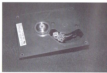
Figure 3.1 Radial optical assembly
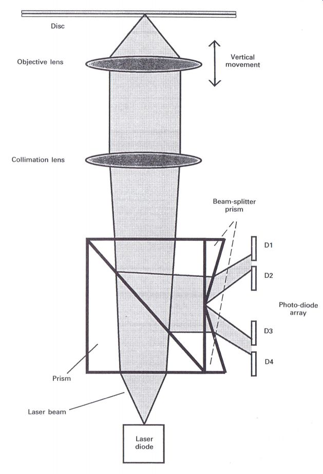
Figure 3.2 Philips optical assembly
Single-beam device with linear/straight line tracking
Single-beam devices with linear tracking (Fig. 3.3) are usually found in the Panasonic/Technics models, though this type did appear in the first Pioneer in-car CD players.
In this type the objective lens has the capability of moving vertically to achieve focus, and laterally for tracking, but as there is only a limited amount of lateral movement of the lens (~ 2 mm), a method of moving the optical assembly across the surface of the disc, at right angles to the track, has to be achieved.
As with the previous device, the photo-diode array comprises four photo-diodes to develop the data, focus and tracking signals. Later versions may contain six photo-diodes for improved operational capabilities with scratched or marked discs.
Three-beam device with linear/straight line tracking
It could be said that this type of optical assembly will appear in the majority of the players originating from the Far East, e.g. Akai, JVC, Kenwood, Panasonic/Technics, Pioneer, Sanyo, Sansui, Sony, Toshiba and Yamaha.
With these units, three beams are provided, where the main or center beam provides data retrieval as well as focus information and two side beams provide tracking signals. The objective lens is able to move vertically and laterally in a similar fashion to the previously described device.
In order that the two extra beams can be obtained from the single laser beam a diffraction grating is necessary. Again the lens has only a limited amount of lateral movement, and therefore a method of moving the complete assembly gradually across the surface of the disc has to be found (Fig. 3.4).
Referring to any of any of the illustrated optical blocks, similarities will occur with respect to the main components. Occasionally it can be observed that different manufacturers choose to include certain component arrangements or concepts that will suit a specific design criterion, but overall the operation of all optical blocks will be generally similar regardless of their manufacturing origin.
Exceptions to this rule are those optical blocks that do not contain tracking coils (which is typical of Philips) and those that have a diffraction grating (which is typical of the Pioneer CD players). The following descriptions apply to any or all of the illustrated optical blocks, with additional information as applicable, commencing from the laser diode and effectively progressing through the optical block, until the reflected light reaches the photo-diode array.
Components of optical blocks
Laser diode
The laser beam is essentially the controlling feature of the CD system insomuch that this type of light operates at a specific frequency (~ 790 nm), whereas white light covers a wide range of frequencies. Because of this specific frequency of the laser beam, it is possible to achieve a beam width in the region of 0.6 pm within a CD player, thus enabling the reading of the data from a disc containing a track width of 0.5 pm--a feature that is not possible with white light. The power of the laser is extremely small; in the region of 0.23 mW in the early CD players, to around 0.12 mW in the majority of the players currently available.
It is essential to maintain the light output level of the laser diode at a consistent level, which is achieved by monitoring a portion of the laser output via a photo or monitor diode, and feeding the registered level back through an automatic power control circuit where it is compared to a predetermined level which can be adjusted by the laser power control, thereby stabilizing the light intensity output at the setting determined by the relevant manufacturer.
The laser diode is switched On and Off via the LDON line which is originally controlled from the system control (Fig. 3.5).
Diffraction grating
Diffraction grating is an extremely small special lens that will produce three beams from the single beam of the laser diode. It can be compared to the special 'add on' lenses that can provide multiple images of a single scene for photographic or Video cameras, though the actual size of the lens or grating is extremely small.
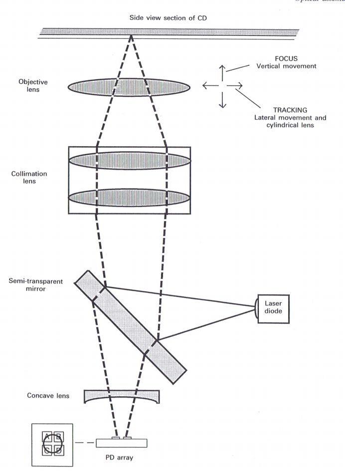
Figure 3.3 Single-beam optical assembly
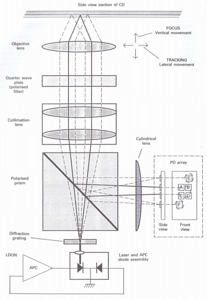
Figure 3.4 Three-beam optical
assembly
This element will only appear in the three-beam
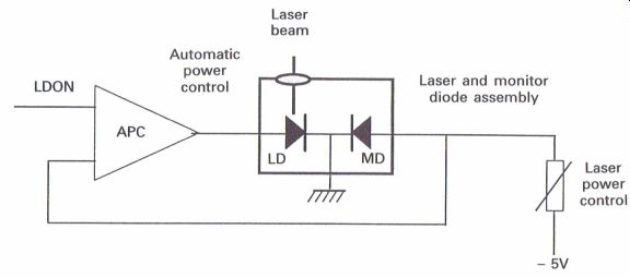
Figure 3.5 Laser diode power control devices, where the extra two beams,
frequently referred to as side beams, will enable the signal for the tracking
servo to be achieved. With some manufacturers, typically Pioneer, there
is a requirement to adjust the grating whenever it proves necessary to
replace a faulty optical block. The method for adjustment of the diffraction
grating is fully described under the adjustment procedures in Section
6.
However, the latest Pioneer optical block (the 92 series) does not require
the grating to be adjusted as it is factory set during manufacture.
Prism--Three-beam optical block
Depending upon the type of optical block, there may be more than one prism. Essentially it is required to separate the direct laser beam going towards the disc from the reflected beam from the disc for processing by the photo-diode array.
The reflective surface of the prism is frequently covered with polarizing material which will enable the reflected beam to be efficiently separated from the main or direct laser beam. Typical of this arrangement is the illustrated three-beam device.
Semi-transparent mirror--single-beam optical block
This reflects the laser beam towards the collimation and objective lenses and onto the surface of the disc.
Collimation lens
The collimation lens together with the objective lens ensures that the laser beam achieves focus on the playing surface of the CD.
Quarter wave plate--three-beam optical block
The direct laser beam passing through this plate towards the CD is optically altered by 45°, and the returning beam is altered by a further 45°, therefore causing the optical polarization between direct and reflected beams to differ by 90°. The reflected beam is now of the correct polarization to enable efficient deflection within the prism towards the photo-diode array.
Objective lens
The objective lens is capable of vertical movement in all optical assemblies to achieve focus of the laser beam onto the CD, and in many players is capable of lateral movement to enable the optical assembly to follow the track of the disc.
In players that use the radial method of track following, as in the majority of Philips players, the objective lens does not move laterally.
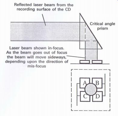
Figure 3.6 Critical angle prism --- Reflected laser beam from the recording
surface of the CD; Critical angle prism; Laser beam shown in-focus. As
the beam goes out of focus the beam will move sideways, depending upon
the direction of mis-focus.
Cylindrical lens--three-beam optical block
The function of this lens is to enable the reflected beam from the CD to assist in creating the necessary signal to ensure that focus of the laser beam onto the playing surface of the disc can be maintained.
When the beam is correctly focused, a round beam of light will land on the four photo-diode elements, as shown in Fig. 3.12. However, if the beam becomes out of focus, the cylindrical lens will in effect distort the beam elliptically (frequently referred to as 'astigmatism') as illustrated, depending upon the direction of mis-focus. Further description of how this achieves the focus error signal is given under the section on Photo Diode Arrays.
Critical angle prism
An alternative method of determining focus can be achieved with the critical angle prism system, as shown in Fig. 3.6.
The critical angle method utilizes an optical phenomenon when mis-focus occurs, where the reflected beam moves fractionally sideways as the result of passing through a prism at a specific angle, with the amount of deflection being related to the direction and amount of mis-focus.
Beam-splitting prisms--Philips optical block
This method of determining mis-focus and mistracking is usually found in the Philips players and some of the Sharp and Panasonic/Technics players, and is further described under the section on photo-diode arrays.
Concave lens--single-beam optical block This concentrates the reflected beam onto the photo-diode array, and improves sensitivity.
Photo-diode arrays
Depending upon the type of optical assembly involved, the photo-diode array will usually comprise either four or six diodes, with the prime function of developing the data, focus and tracking signals, which are the result of the reflected laser beam from the playing surface of the CD (Fig. 3.7). However, the latest Pioneer optical block has five photo-diodes, which together with a hologram prism provide a somewhat different method of processing the reflected beam (see Fig. 3.17).
It is the photo-diode array, whatever its form, that is required to produce the three main signals to enable a CD player to operate effectively:
1. data information: to enable the music or other information to be produced;
2. focus error: to ensure that the laser beam remains in focus on the disc whilst it is being played; and,
3. tracking error: to enable the laser beam to track across the playing surface of the disc.
To produce the data information from the diodes is relatively straight forward by adding the sum of the four diodes (A + B + C + D) together and together with the necessary amplification, an RF signal will be obtained, which will be later referred to as the 'RF eye pattern waveform', and will be described in later sections.
The focus and tracking error signals are developed by various methods of combining the diodes to produce the required signals which will operate the focus and tracking servos, and whilst these will be covered in Section 4, the various methods of developing these signals will now be described.
-------------
Four-element photo-diode array (as used in single-beam radial traverse optical assemblies) Four-element photo-diode array _ (as used in single-beam optical assembles)
Six-element photo-diode array (as used in three-beam optical assemblies)
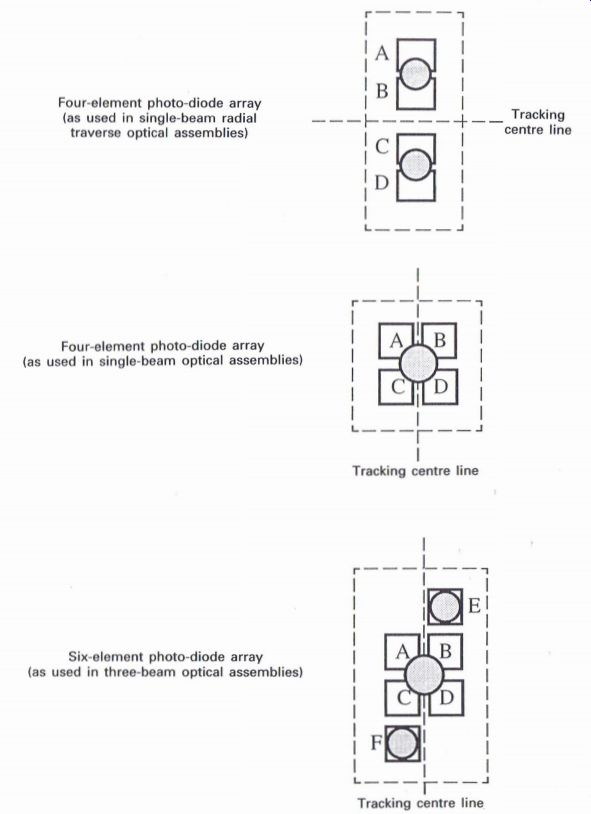
Figure 3.7 Comparison of photo-diode arrays
------------
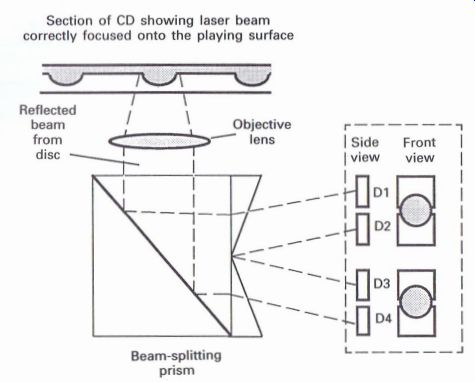
Figure 3.8 Beam-splitting prism: in-focus condition with the photo-diodes
receiving equal amounts of reflected light
Beam-splitting prism
Developing the focus signal
This method is used in the Philips radial tracking optical assembly which is a single laser beam unit.
It is the shape of the prism that causes the reflected beam to be split into a pair of equal beams (Fig. 3.8).
Each beam will land equally onto a pair of diodes when the in-focus condition has been achieved, but as mis-focus occurs, the two beams will effectively move outwards or inwards depending upon the direction of focus error (as shown in Fig. 3.9).
Developing the tracking signal
When the laser beam is directly on the track of the disc, the reflected light will appear as an equal pair of beams which each land onto a pair of photo-diodes (Fig. 3.10). As the disc rotates, the reflectivity from the track will alter, causing the light intensity monitored by each pair of beams to vary (as shown in Fig. 3.11).
As there is a difference of light intensity in relation to the amount and direction of tracking error, it is now possible to develop a tracking error signal for the tracking servo.
Four-element photo-diode array
Developing the focus signal
Two methods can be described, with one type using a cylindrical lens which produces astigmatism, a form of distortion of the reflected laser beam as mis-focus occurs (Fig. 3.12). The other method is the critical angle prism which produces a slight sideways movement of the reflected laser beam when mis-focus occurs (Fig. 3.13).
When the laser beam is in focus, the cylindrical lens will produce a round beam of reflected light spanning the surface of the four photo-diodes, but when mis-focus occurs, the cylindrical lens will distort the reflected beam virtually into an ellipse, which will span the diodes (B + C) or (A + D), depending upon the direction of the
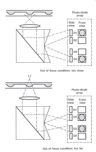
Figure 3.9 Beam-splitting prism: method of achieving focus error
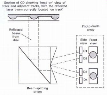
Figure 3.10 Beam-splitting prism: on-track condition. The pairs of photo-diodes
will receive equal amounts of reflected light
---------------
Section of CD showing 'head on' view of track and adjacent tracks, with the reflected laser beam correctly located 'on track' Beam-splitting prism Photo-diode array
------------
focus error. By cross connecting the diode pairs (B + C) and (A + D), it is possible to develop a focus error signal.
Critical angle prism
The reflected beam is directed onto the four photo-diodes via the critical angle prism, which is a reflective surface set at approximately 42°. As mis-focus occurs, the reflected beam will move fractionally sideways to land either on the (A + C) or (B + D) diode pairs (Fig. 3.13). Therefore, depending upon the direction of mis-focus, it is possible to develop a focus error signal to maintain the laser beam in focus on the disc.
Developing the tracking error signal With the four photo-diodes it is possible to connect them in two ways to enable a tracking error signal to be developed, either by connecting them in pairs (A + C) and (B + D), or diagonally as (A + D) and (B + C).
Push-pull method
With a push-pull arrangement the photo-diodes are connected in pairs (A + C) and (B + D) (Fig. 3.14). When the laser beam is on track the reflected light intensity on the two pairs is identical and when applied to the tracking error amplifier, will produce a zero tracking error output.
As the track moves to one side or the other, the light intensity received by the two pairs will vary, resulting in a difference between the two pairs, which will provide a tracking error output from the amplifier that will relate to the direction of the tracking error.
This is probably one of the easier methods of obtaining a tracking error signal (compared to, for example, the phase difference method).
Phase difference method
With the phase difference method (Fig. 3.15) the photo-diodes are cross connected in pairs (A + D) and (B + C). Each pair is fed to a summing amplifier and also a differential amplifier, where
--------------
Section of CD showing 'head on' view of track and adjacent tracks, with the reflected laser beam tracking off to the right of the required track Photo-diode array Section of CD showing 'head on' view of track and adjacent tracks, with the reflected laser beam tracking off to the left of the required track Photo-diode array
Off track condition: as the reflected laser beam tracks either side of the track, the light intensity monitored by the pairs of photo-diodes will vary depending upon to which side the mis-tracking occurs
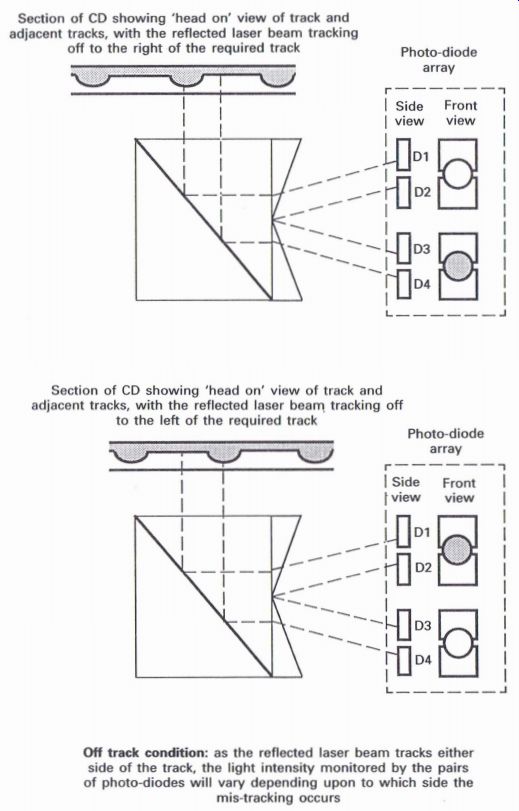
Figure 3.11 Beam-splitting prism: method of achieving tracking error
---------------
Mis-focus In one direction
Mis-focus in opposite direction
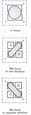
Figure 3.12 Four-element PD array: method of achieving focus error I
-------------------------
further processing takes place as described under the relevant section in Section 4. It is possible to produce a tracking error signal that is related to differences in phase which are the result of the amount of tracking error signal.
Three-beam optical block method of achieving tracking error
The three-beam optical block (Fig. 3.16) is probably one of the most common types of optical blocks in recent years. Whilst the block has a single laser beam, it is possible to produce three beams by passing the beam through a diffraction grating lens (not too dissimilar to the type of lens that can be attached to the front lens of a camera to be able to produce multiple images of the same scene).
The center beam is used for data retrieval from the disc, and also to enable the focus error signal to be produced. The two outer beams are used for developing the tracking error signal, and are arranged to land upon the (E) and (F) photodiodes.
It is possible with some types of optical blocks, especially the Pioneer types, to adjust the diffraction grating to align correctly onto the (E) and (F) photo-diodes, but many types are factory set, and therefore require no further adjustment.
As the disc rotates, and assuming that the tracking is correct, the reflected light beams from the disc will land onto the photo-diode array as shown in Fig. 3.16, with the beams for the (E) and (F) photo-diodes receiving reflected light from either side of the track, which will relate to zero tracking error.
When a tracking error occurs on one side or the other of the track, the reflected light monitored by the (E) and (F) photo-diodes will now vary with respect to each other, depending on which side of the track the error occurs, and this will result in a signal the value and polarity of which will be related to the amount and direction of the tracking error.
Pioneer '92 optical block
Compared to previous types of optical blocks, the most recent Pioneer type (Fig. 3.17) has three major variants: a five-element photo-diode array, 3 hologram prism, and the laser diode and photodiode array contained within the same component (these are usually individual components placed in different areas of the complete optical block).
The single laser beam passes through a diffraction grating to develop the three beams, in common with many modern optical blocks, which pass directly through the hologram prism area towards the surface of the disc via a polarized objective lens.
Previous optical blocks have usually contained a polarizing prism to ensure that the reflected beams are optically correct to be defected towards ...
---------------------
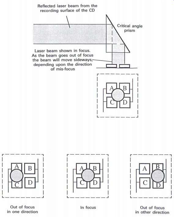
Figure 3.13 Four-element PD array: method of achieving focus error 2
Reflected laser beam from the recording surface of the CD
Laser beam shown In focus.
As the beam goes out of focus the beam will move sideways, depending upon the direction of mis-focus Critical angle pr ism
Out of focus in one direction
In focus; Out of focus in other direction
------------------------
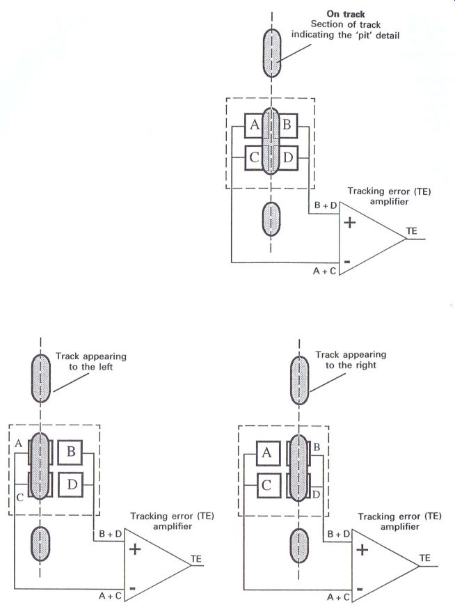
Figure 3.14 Four-element PD array: push-pull method
---------------------
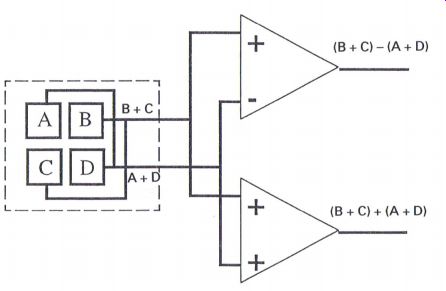
Figure 3.15 Four-element PD array: phase difference method the photo-diode
array by the relevant prism.
Polarizing the objective lens fulfills the same requirement whilst reducing the number of components within the block.
The reflected beams will now be in the correct optical phase or alignment to ensure that the beams are now defected sideways by the hologram prism towards the photo-diode array which also splits each beam into two, making six beams land onto the five-element photo-diode array (Fig. 3.18).
The five diodes shown in Fig. 3.18 provide the necessary signals as follows:
1. (D1) and (D5) are used to produce the tracking error signal;
2. (D2) and (D3) are used to produce the focus error signal; and,
3. the sum of (D2), (D3) and (D4) is used to produce the RF eye pattern waveform.
With the tracking passing through the center of the array as illustrated in Fig. 3.18, any sideways deviation or error will be monitored by (D1) and (D5) to produce the tracking error signal as described above for the three-beam optical block method.
The focus error signal is detected by (D2) and (D3), which will monitor a slight sideways movement as mis-focus occurs 4 a technique which is similar to the critical angle prism method.
With the sum of (D2), (D3) and (D4), the RF signal produced will have improved benefits compared to some previous types. When scratched discs are played there is a tendency for skipping and jumping to occur due to the interference the scratches cause to the reflected beams, as well as sound glitches being caused by the RF signal being occasionally disrupted.
Ideally, to maintain effective focus and tracking, the size of the photo-diodes needs to be small in order that the focus and tracking servos do not respond to large noise spikes due to scratches, whilst it would be beneficial if they were larger to be able to respond more effectively to the 'pit' information to produce the RF signal, and meeting these ideals would possibly enable discs with reasonably small scratches to be played more effectively.
With the five-element array, the (D1), (D2), (D3) and (D5) diodes are small, whilst the (D4) diode is significantly larger. As the hologram prism produces six beams, these will also be small to be accommodated onto the photo-diodes, and this will result in the diodes and beams being small for effective focus and tracking, whilst the area of the (D2), (D3) and (D4) diodes will be larger to enable an improved RF signal to be developed.
---------------
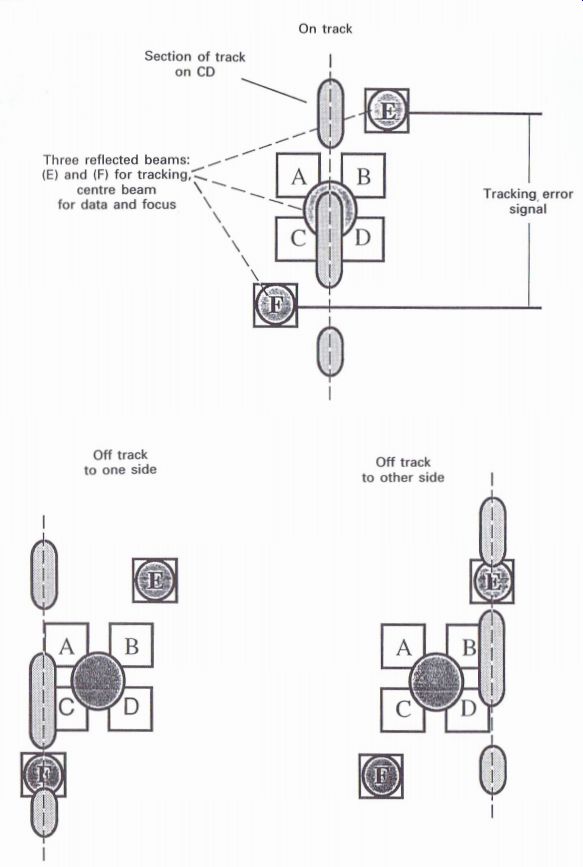
Figure 3.16 Six-clement PD array: method of achieving tracking error
--------------
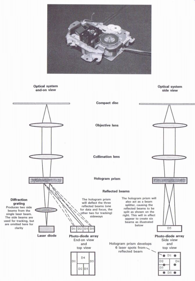
Figure 3.17 New Pioneer '92 optical block using a hologram prism
Diffraction grating--Produces two side beams from the single laser beam.
The side beams are used for tracking, but are omitted here for clarity
Reflected beams---
The hologram prism will deflect the three reflected beams (one for data and focus, the other two for tracking) sideways
The hologram prism will deflect the three reflected beams (one for data and focus, the other two for tracking) sideways
The hologram prism will also act as a beam splitter, causing the reflected beams to be split as shown on the right . This will in effect appear to create six beams as illustrated below
----------------------
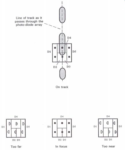
Figure 3.18 New Pioneer '92 optical block, five-element PD array: method
of achieving focus error
------------------