In order that the data can be retrieved from the CD, it is necessary to maintain the laser beam in focus on the playing surface of the disc, as well as being able to gradually track across the playing area. This is achieved via a range of servo systems which provide the requirements of focus, tracking and disc rotation.
Whilst players may differ from one manufacturer to another, the basic function of any of the servo systems will be similar. The basic servo (Fig. 4.1) can be considered to comprise:
1. a sensing element,
2. an amplifier system, and,
3. a controlled element.
Because the various stages of a servo system are d.c. coupled, it will be necessary to include some form of offset adjustment to neutralize undesirable d.c. potentials within the system, as well as a gain control to enable optimum operating efficiency to be achieved.
Some players may well have some form of automatic method of correcting for any undesirable d.c. offset potentials, as well automatic gain adjustment.
The sensing element will comprise components of the photo-diode array referred to in Section 3.
It will provide a signal that will be in relation to any errors that may have been sensed. These signals are processed
Within an amplifier system which will normally include some form of frequency shaping to optimize the operation of a specific servo system, before passing on to the controlled element. This will normally be in the form of a coil to operate a lens or motor to drive the CD or move the optical assembly across the surface of the disc, continuously neutralizing the errors as they are being sensed.
As described in Section 5, various switching operations will take place within any of the servo systems, which are controlled by the system control circuit to ensure that the correct operational sequence of the player takes place.
Focus servo
The photo-diode array will provide the initial focus information, via an amplifier and a control system, to develop a signal to be applied to the focus coil which is attached to the objective lens (Fig. 4.2).
Depending upon the CD player manufacturer, the photo-diode array will comprise either a combination of four photo-diodes (see Fig. 3.7), or three of the five photo-diode arrays used in the Pioneer '92 optical block (Figs 3.17 and 3.18).
When the CD player is first switched on and prior to the commencement of playing a CD, it is necessary to ensure that the laser beam is focused correctly on to the playing surface of the disc. To achieve this it is necessary for the focus lens to 'search' for the correct focal point, by applying a specific search signal to the focus servo system, to cause the lens to physically move vertically, until focus is achieved.
At the point of correct focus, a maximum reflected signal will be received from the disc. This will result in a focus OK (FOK) signal, which is passed onto the system control circuit to enable the next stage of player operation, and in the case of many CD players, indicate that a CD is present.
Various methods exist for determining the focus error signals, as indicated in Section 3, but it is now relevant to consider some of the applications within some of types of focus servo systems that have appeared in some types of CD players.
Beam-splitting photo-diode array method
A beam-splitting photo-diode array (Fig. 4.3) is consistent with the radial traverse optical systems that have been extensively used in Philips and Marantz CD players, as well as some Technics and players of other manufacture.
---------------
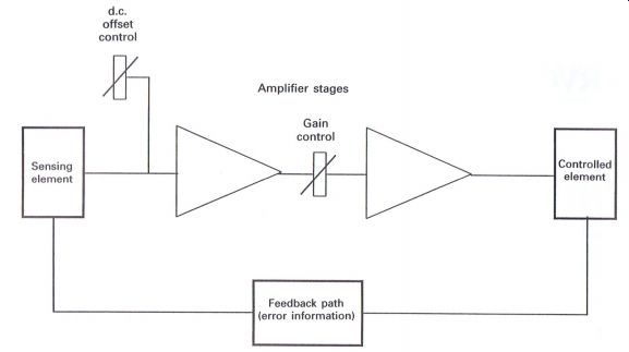
Figure 4.1 Basic servo system
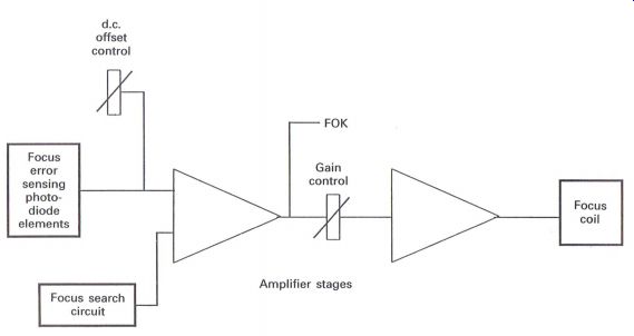
Figure 4.2 Basic focus servo system
---------------
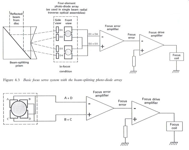
Figure 4.3 Basic focus servo system with the beam-splitting photo-diode
array; Figure 4.4 Basic focus servo system with the four-element photo-diode
array (as used in single-beam optical assemblies, using the cylindrical
lens or astigmatism method)
When the reflected beam from the surface of the disc is in focus, the two beams of light from the beam-splitting prism will land on the two pairs of photo-diodes, as shown in Fig. 4.3. The resultant inputs to the focus error amplifier will comprise (D1 + D4) and (D2 + D3), with the output being the difference between the two inputs, which for the in-focus condition will be a zero error signal.
Ideally the focus lens will be in a neutral or mid-point position.
As mis-focus occurs, the two beams will move outwards towards either the D1 and D4 diodes, or inwards towards the D2 and D3 diodes. The resultant output from the focus error amplifier will be a potential, the value and polarity of which will be related to the amount and direction of focus error.
Applying this signal to the focus coil via the focus drive amplifier will enable the focus lens to move in the direction to correct the focus error and maintain the laser beam correctly focused on the playing surface of the CD.
Cylindrical lens--four-element photo-diode array method
The cylindrical lens method (Fig. 4.4) is possibly the most frequently used system of focus servo ...
-----------------------------
Reflected laser beam from the recording surface of the CD Laser beam shown in-focus.
As the beam goes out of focus the beam will move sideways depending upon the direction of mis-focus
-------------------
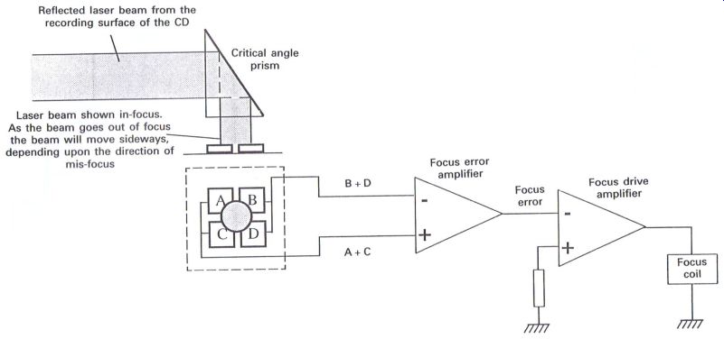
Figure 4.5 Basic focus servo system with the four-element photo-diode
array (as used in single-beam optical assemblies, using the critical angle
prism method of focus control) control, and is typical of single-beam (four
photodiodes) or three-beam (six photo-diodes) types of optical block.
With the in-focus condition, the reflected beam will equally cover the four photo-diodes. As the opposite diodes are connected together, i.e. (A + D) and (B + C), the resultant potentials fed to the focus error amplifier will be the same, providing a zero error focus signal output which is applied to the focus coil via the focus drive amplifier, once again enabling the focus lens to achieve a neutral or mid-point position.
As mis-focus occurs, the reflected beam will become elliptical due to astigmatism caused by the cylindrical lens. This will cause the potentials (A + D) or (B + C) to differ with respect to each other, thereby creating a focus error signal which will enable the focus lens to move in the required direction to correct any mis-focus that may occur.
Critical angle prism--four-element photo-diode array method
The critical angle prism is an alternative method of utilizing a four-element photo-diode array, and was used in earlier types of single-beam optical blocks. It makes use of a phenomenon where the reflected beam is directed via a prism, which is set at a 'critical angle' of 42°. As mis-focus occurs the beam will move fractionally sideways across the surface of the photo-diodes (Fig. 4.5).
With this system the photo-diodes are connected in pairs (A + C) and (B + D), which will result in identical inputs being applied to the focus error amplifier when the beam is correctly focused onto the playing surface of the disc.
Mis-focus will cause the reflected beam to move fractionally sideways, resulting in the potentials (A + C) and (B + D) differing with respect to each other, which in due course will enable the focus lens to move in the direction to correct any focus error.
Hologram method of focus servo
With the hologram method (Fig. 4.6), whilst the basic circuit concept of the focus servo still remains similar to previous circuits, the error signal, which is developed from only two of the photo-diodes, D2 and D3, is applied to the focus error amplifier. When the laser beam is on-focus, minimum output will be achieved from the focus error amplifier, whilst mis-focus will enable a potential to be produced which will relate to the amount and direction of the focus error.
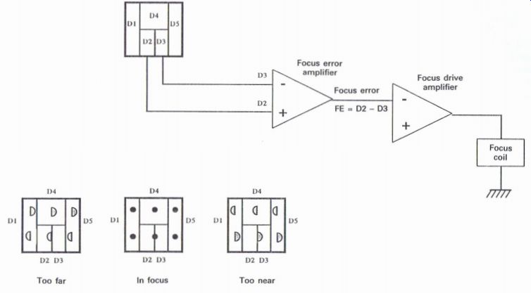
Figure 4.6 Basic hologram method of focus servo system
Tracking servo Whilst the various focus servo systems are basically similar, the various types of tracking servos that have appeared in CD players vary in their complexity. Probably the three-beam optical assembly, where the two extra beams are used specifically for developing the tracking error signal, has proved to be the most popular and least complex.
However, developing the tracking error from a four-element photo-diode array or single-beam optical block can require some specialized signal processing circuits.
Whilst various types of tracking servo exist, two particular groups of optical block have been used throughout the numerous ranges of CD players that have been produced. Either the objective lens is fixed laterally, such as in the Philips radial tracking system, or the lens has a small amount of lateral movement which enables the lens to track gradually across a small surface area of the disc, which in turn is co-ordinated with a motor drive system to gradually move the complete optical assembly across the surface of the disc.
Basic tracking servo with lateral movement of the lens
The tracking error signal is derived from the relevant photo-diodes, which can comprise two diodes from either a four photo-diode array used with single-beam optical blocks, or from a five or six photo-diode array, normally associated with a three-beam device (Fig. 4.7).
A range of adjustments may be included within the tracking servo circuit in order to optimize the operation (see Section 6).
Because a tracking error signal has to be developed that will be related to the amount of deviation of the laser beam either side of the track on the CD, many CD players will include a tracking balance control to ensure that equal amounts of deviation of the laser beam either side of the track will result in equal and opposite polarity error signals.
As the disc rotates, a continual tracking error signal will be developed which is applied to the tracking coil Via the necessary amplifier stages to continually neutralize the tracking error signal.
---------
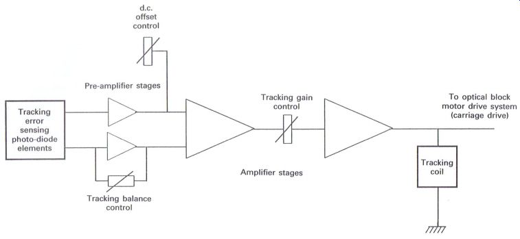
Figure 4.7
Basic tracking servo system -- lateral lens movement type
-------------
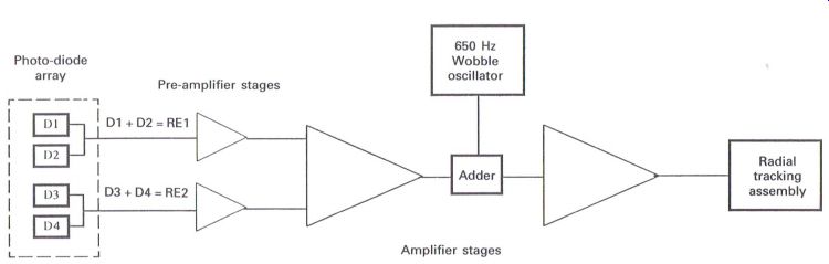
Figure 4.8 Basic radial tracking servo system -- fixed lens system.
----------------
The tracking coil will have a lateral movement of only a few millimeters, and therefore it is necessary to monitor the signal being applied to the tracking coil circuit. This signal will be in the form of an increasing potential, and will be in proportion to the lateral movement of the tracking coil and lens combination. As the signal reaches a certain level, a motor drive system will enable the optical block to gradually 'creep' across the surface of the disc. Therefore there is a continual compromise situation between the tracking coil and the motor drive system to effectively maintain efficient tracking across the surface of the disc.
The motor drive system has various identifications depending upon the manufacturer of the CD player: carriage, sled, sledge and slider, and no doubt other options, are in existence.
Basic tracking servo: radial tracking system The radial tracking type of tracking servo (Fig. 4.8) is usually associated with the Philips and Marantz players, as well as some Sharp and Technics players. Other manufacturers have also utilized this method.
The major difference with this concept is that the objective lens is fixed, and that the complete
Objective lens
---------------
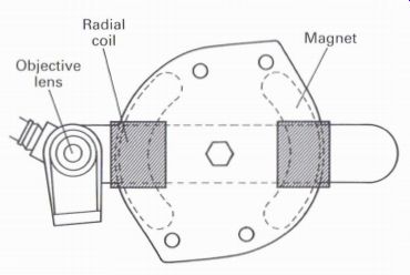
Figure 4.9 Diagram of radial tracking assembly
--------------------
optical assembly moves laterally across the surface of the CD, in a manner similar to a moving coil meter (Fig. 4.9).
As this arrangement requires the complete optical assembly to move minutely in fractions of a micrometer, problems can occur with respect to tracking and friction. A term which some engineers may be familiar with relating to this type of friction in servo systems is static friction or 'stiction', which was quite common in early mechanical servo data transmission systems.
These early systems were used very much in the armed forces to relay such information as compass bearings from one central source to indicators situated in remote areas within a specific environment such as a ship or aircraft. To over come the 'stiction' problem it was necessary to inject a high audible frequency source. This was referred to as a 'dither' frequency, and enabled the indicators to respond to small movements of information such as a gradual change in compass bearing as the ship or aircraft changed direction.
A similar method is introduced in the radial tracking system with the insertion of a 650 Hz wobble frequency, which causes the optical assembly to continually 'wobble' or oscillate either side of the track on the disc.
The radial optical assembly moves in an are (as indicated in Fig. 4.10). When the optical unit is at the start or center of the disc, the angle of the photo-diode array will be at right angles to the track, whilst towards the outer edge of the disc the angle will alter to approximately 45 degr -- a situation which could cause problems with respect to discerning the tracking error signal.
The four-element photo-diode array is arranged as two pairs of photo-diodes side by side, and the radial tracking error is developed from the signals D1+D2=RE1 and D3+D4=RE2.
The 'on-track' condition will enable (D1 + D2) and (D3 + D4) to receive equal amounts of the reflected laser beam from the disc, causing equal potentials of RBI and REZ to be produced, which will result in a zero radial tracking error signal.
As the disc rotates and tracking errors are developed, the resulting levels of the RBI and REZ potentials will vary according to the direction and amount of deviation of the reflected beam from the center of the track, which will result in a radial tracking. The error signal will vary in level and polarity, depending upon the amount and direction of tracking error.
Because of the changing angle of the photo diode array with respect to the track as the optical block travels across the surface of the disc, the tracking error signal will not vary in proportion to the actual radial movement of the optical block, and can cause possible asymmetry of the reflected signal.
If the optical block, and consequently the photodiode array, were to traverse gradually across the surface of the disc, a tracking error signal would be produced that would vary depending upon the position of the photo-diode array in relation to the individual tracks. Optical blocks that move linearly at right angles to the track will develop a consistent quality of tracking error signal across the disc that is proportional to the amount of movement of the optical assembly (Fig. 4.11).
But with the radial tracking method, the quality of the tracking error signal will deteriorate towards the outer edge of the disc as the angle of the photodiode array alters with respect to the track. To minimize this undesirable effect, it is possible to make use of the effect of the 650 Hz wobble frequency that is applied into the radial tracking circuit. Fig, 4.12(a) illustrates the variation in level of the reflected light output or eye pattern waveform, which is related to the position of the photo-diode array compared to track position. When the array is effectively 'on track' the reflected signal will be at a minimum due to deflection of the laser beam onto the 'pits' or 'bumps' resulting in a reduction of actual reflected light, and consequently the resultant signal.
When the photo-diode array is between tracks, maximum reflection occurs, due to the mirror surface between tracks, and therefore results in a maximum signal level developing.
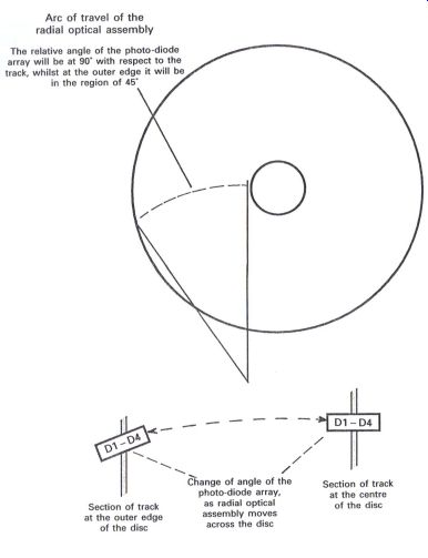
Figure 4.10 Radial optical assembly
On-track condition
By enabling the radial assembly to wobble or oscillate at a frequency of 650 Hz either side of the track, and assuming an 'on-track' situation, the basic minimum reflected signal which will increase in level as the radial assembly oscillates either side of the track center to produce the waveform (a), which will modulate slightly the eye pattern waveform.
The waveform (a) is applied to the input of the synchronous detector circuit shown in Fig. 4.12(b), as signal X. The synchronous detector switch, which is operated by the 650 Hz + 90° wobble frequency, will alternately provide at the output as signal Z, either the direct signal X or the inverted signal Y.
Therefore during the on-track condition, the output signal Z will comprise alternate positive and negative half cycles which when applied to an integrating circuit will result in zero output.
Off-track to the right
Assuming an off-track condition, say to the right, will result in waveform (b) being applied to the synchronous detector input, which will result in ...
Figure 4.11 Photo-diode/track relationship the output as waveform (d),
and in turn provide a positive signal after integration.
Off-track to the left
For this situation, waveform (c) is now applied to the input of the synchronous detector, which in turn will result in waveform (e), i.e. a negative signal when integrated.
Therefore this method will enable a generally consistent quality of radial tracking error signal to be developed as the radial optical assembly gradually tracks towards the outer edge of the disc.
However, it is possible for other factors to affect the efficient operation of this tracking method, and these are related to the laser power, the reflective qualities of the disc itself, and possible phase differences of the wobble signal applied to the radial assembly when they are compared to the resulting wobble frequency that must be present on the radial tracking error signals at either the beginning or the end of the CD as the photo-diode angle alters.
These factors can influence the overall gain of the radial tracking servo system, and can result in inefficient and unstable operation. Therefore it is necessary to maintain a consistent gain throughout the overall operation of the radial tracking servo.
To achieve an effective gain control it is necessary to compare the phase of the wobble frequency applied to the radial assembly to that present on the radial tracking error signal, and as the phase alters the gain is varied accordingly.
The 650 Hz wobble oscillator is fed via adder (5) into the radial servo system which will cause the radial motor to oscillate by the extremely small amount of 0.1 pm, and will result in radial error signals which are developed via the four photo diodes, DleD4, to be 'modulated' with the 650 Hz wobble frequency (Fig. 4.13).
The signal outputs from the four photo-diodes, D1-D4, are connected after amplification and via the adders (1) and (2) to provide the two radial error signals (D1 + D2) = RB1 and (D3 + D4) = RE2.
The amplifiers for each of the diodes are gain controlled in relation to the sum of the radial error signal, and the level of the RF signal determined from the sum of the four diodes.
From Fig. 4.13 it can be determined that the sum of D1-D4 is passed to the RF amplifier stages, which includes a high frequency stage and an equalization stage to provide the standard RF eye pattern waveform, for further processing in the decoder circuits, but it is also fed via the HF slice stage to maintain specific limits, to the gain control stage.
The sum of RE1 and RE2, which is derived via adder (3), is passed through a low pass filter (LPF) to remove the 650 Hz content, and fed to the gain control stage. The resulting sum from these two signals will provide a d.c. level to maintain the gain of the first amplifier stages within defined limits.
The complete radial servo signal path comprises ...
-------------------------
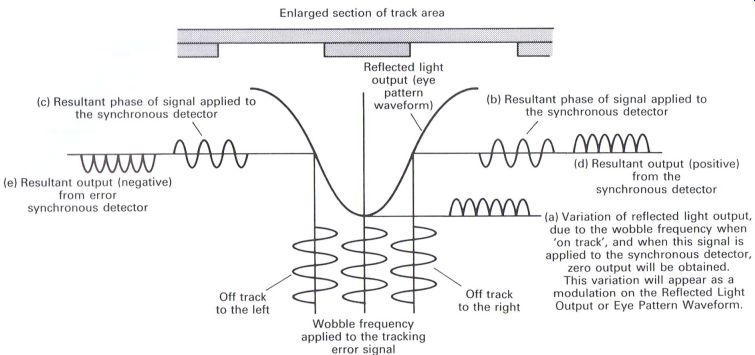
Figure 4.12(a) Relative phase of the 650 Hz wobble frequency, in relation
to track position
(c) Resultant phase of signal applied to the synchronous detector (e) Resultant output (negative) from error synchronous detector Off track to the left output Reflected light pattern waveform)
Enlarged section of track area (eye (b) Resultant phase of signal applied to the synchronous detector
V (d) Resultant output (positive) from the synchronous detector (a) Variation of reflected light output, due to the wobble frequency when 'on track', and when this signal is applied to the synchronous detector, zero output will be obtained.
This variation will appear as a modulation on the
Reflected Light Output or Eye Pattern Waveform.
---------------------------
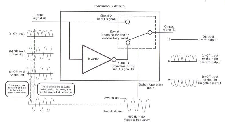
Figure 4.12(b) Operation of the synchronous detector
--------------------------------
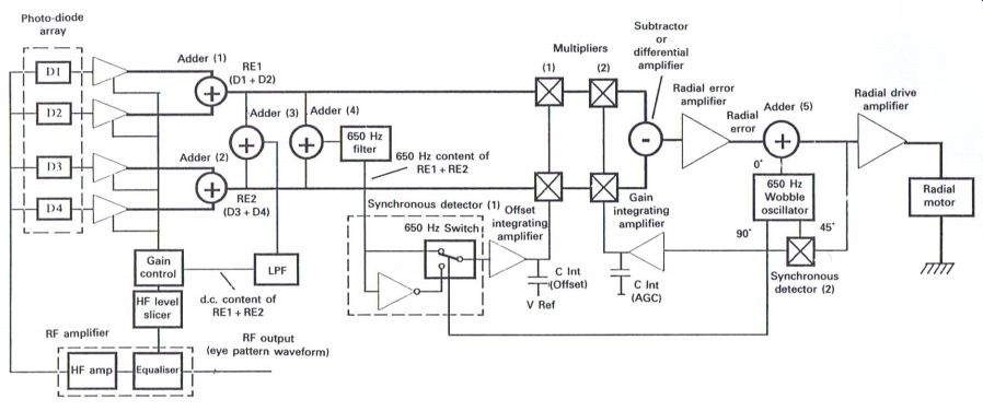
Figure 4.13 Radial tracking servo
... the error signals RE] and REZ passing through multipliers (1) and (2), into a subtractor or differential amplifier to provide a radial tracking error signal which continues via the radial error amplifier and adder (5) to the radial motor drive circuit.
Fundamentally, the radial tracking error signal will be a d.c. level which will relate to the amount and direction of the tracking error. However, because of the various problems caused by the movement of the optical assembly (as described above), it is necessary to provide additional processing to maintain a consistent and efficient radial tracking operation.
Radial error signals RB1 and RE2 are combined Via adder (4) and filtered via the 650 Hz
filter to provide the wobble frequency content of the radial tracking error signals, which is now fed to the synchronous detector (1) to provide outputs in relation to the amount of radial tracking error (as illustrated in Fig. 4.12).
An output from the wobble oscillator is fed to the synchronous detector to operate the 650 Hz switch, which will enable the required error signal to be developed. The detector output is passed to the offset integrating amplifier to provide a level, which is related to radial tracking error, and when combined at multipliers (1), together with the RBI and REZ signals, will enable an effective error signal to be achieved.
It was previously mentioned that it was also necessary to maintain a consistent gain which is related to the phase of the original wobble frequency, and the wobble frequency content of the radial tracking error signal being applied to the radial drive circuit. This is achieved at the synchronous detector (2) resulting in an output which after processing in the gain integration circuit provides a level which is passed to the multipliers (2).
The following tracking servo descriptions are now related to the method of moving the optical assembly laterally across the surface of the CD, where the photo-diode array is consistently maintained at right angles to the track. With the exception of the phase difference method (Fig. 4.15), these alternative tracking servo methods prove to be a simpler method of operation than the radial tracking system.
The four photo-diode arrays always relate to single-beam optical assemblies, whereas the five and six photo-diode arrays are used in the three-beam optical assemblies, which would generally appear to be more widely used types of optical assemblies.
With the push-pull tracking servo (Fig. 4.14) the photo-diodes are connected in pairs (A + C) and (B + D). When the laser beam is on track, there will be equal amounts of reflected light received by the two pairs of diodes, which when applied to the first tracking, or differential amplifier, will result in zero output.
As the track moves to one side as the disc rotates, the proportions of reflected light on the two pairs of diodes will differ, providing a tracking error (TE) output from the differential amplifier
----------------------
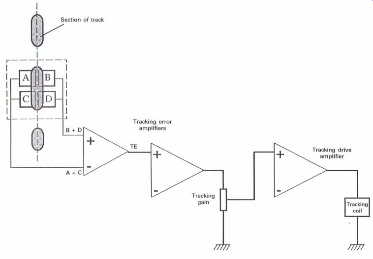
Figure 4.14 Push-pull method of tracking servo that will relate to the
amount and direction of tracking error, which in turn will enable the tracking
coil to move in the correct direction to maintain its position on the track.
With the phase difference method of tracking servo (Fig. 4.15), again the photo-diodes are connected in pairs, but this time as (A + D) and (B + C). The outputs from the two pairs are fed to a differential amplifier and also a summing amplifier, with the differential amplifier producing at the output the difference between the two inputs, i.e. (B + C)--(A + D), and the summing amplifier producing an output of (A + D) + (B + C).
Referring to the graphical representation in Fig. 4.16, and considering the two waveforms drawn to represent the effect as a 'pit' passes through the photo-diode array, the output from the differential amplifier will indicate zero output for the 'on-track' condition, whilst a maximum amplitude signal will be produced from the summing amplifier.
For the 'off-track' conditions the differential amplifier will produce a varying amplitude signal, depending upon the 'pit' position, whilst the summing amplifier will produce a reduced amplitude signal. If a series of 'pits' were considered, then the resultant outputs would be similar, but the frequency intensity would increase in proportion to the periodicity of the 'pits'.
The output from the summing amplifier is passed to a signal processing stage to produce the RF eye pattern waveform, but an output is also passed to the zero cross detector, which will enable the sample and hold circuits to detect the output from the differential amplifier as the RF signal passes through zero.
When the laser beam is 'on track', with the output from the differential amplifier being zero, then the sample and hold circuits will detect zero levels, resulting in zero output from the tracking error amplifier.
During the 'off-track' situations, the phase of the differential amplifier outputs will be different
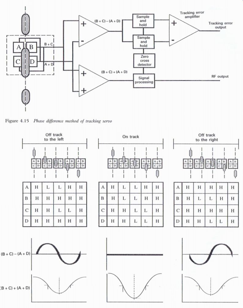
Figure 4.15 Phase difference method of tracking servo
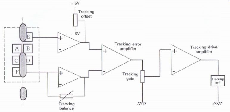
Figure 4.16 Graphical representation of the phase difference method of tracking error detection

Figure 4.17 Three-beam device tracking servo when 'off track' to the left
is compared to 'off track' to the right. Therefore as the RF signal passes
through zero, despite its reduced amplitude, it will be able to enable
a positive or negative error signal to be developed in relation to the
direction of tracking error.
This relatively complex method was used in earlier players, especially Pioneer in-car players, such as the CDX-l and CDX-Pl, and proved quite effective in maintaining track control in a somewhat hostile environment.
Three-beam device tracking servo
The three-beam device (Fig. 4.17) is probably one of the more common methods of tracking servo with the outputs from the (E) and (F) photodiodes detecting any tracking errors as the track passes through the center line of the photo-diode array. Each diode signal is amplified with the outputs being passed to the tracking differential amplifier to produce the tracking error output.
To ensure that the tracking error amplifier produces a signal that will be equal in value but opposite in phase when the same amount of error occurs either side of the track, it is necessary to ensure that the amplifier stages are balanced, this being achieved by the tracking balance control.
With the new Pioneer '92 optical block (Fig. 4.18) photo-diodes (D1) and (D5) fulfill the same function as the (E) and (F) diodes.
Carriage servo
Apart from the radial tracking assembly, all optical blocks allow the objective lens to move sideways Line of track as it passes through the photo-diode array
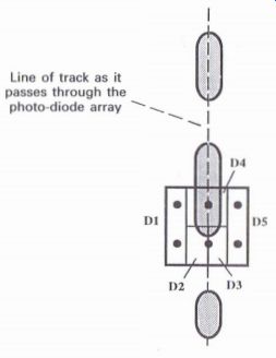
Figure 4.18 Five-element photo-diode
array
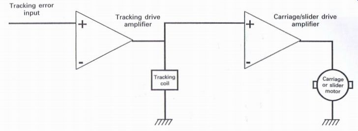
Figure 4.19 Basic carriage servo to enable the tracking servo to ensure
that the laser beam maintains its correct position on the track, but there
is only a very small amount (~2 mm) of sideways or lateral movement.
In order that the optical block can gradually move across the surface of the disc, whilst tracking is being continually maintained, the tracking error signal applied to the tracking coil is continually monitored. As the lens moves laterally, the dc. level of the tracking error signal will be increasing to cause the movement.
Applying this signal to the carriage drive motor amplifier (Fig. 4.19), a value will be achieved that will be sufficient to drive the carriage motor, which in turn will move the optical block an extremely small amount via reduction gearing, either in the form of a thread gear, or a gear and rack system.
Another method is the linear tracking system (Fig. 4.20(c)) where the conventional optical block moves across on a platform that is driven by a linear tracking motor. This type of motor provides an extremely efficient method of moving the optical block across the surface of the disc, as well as to specific areas of the disc when accessing different tracks.
Compared to the conventional gear and rack or thread-driven methods of moving the optical block, the linear tracking system provides almost instantaneous track access.
The varying d.c. potential that is derived from the tracking error signal to drive the carriage motor in the previous example is used to drive the linear motor (Fig. 4.21). This potential after amplification is applied to the drive coil of the linear motor, with the drive coil being set between two bar magnets which are in effect the length of the required travel that is necessary for the optical block to traverse across the surface of the disc.
A feedback coil provides an output that serves the two purposes of developing a speed signal to maintain velocity control, as well as a stop signal at the innermost track position of the disc.
This method of carriage movement provides extremely fast access time to any required area on the disc, compared to the slower thread drive systems.
Spindle servo
The spindle servo (Fig. 4.22) is required to rotate the CD at the correct speed within the range of ~ 180-500 rpm. The data retrieved from the disc are compared to an internal reference within the CD player to produce a control voltage that will drive the disc at a speed compatible with the data rate from the disc.
The effective clock frequency from the disc is 4.3218 MHZ, with 588 bits of the digital information comprising one frame of information.
Dividing 4.3218 MHZ by 588 provides the frame or sync. frequency of 7.35 kHz.
Most of the spindle servo circuitry is contained within the decoder, and despite its complexity its operation proves to be extremely reliable in the majority of CD players. When the CD is operating normally the disc will be running at a speed that will enable the surface speed passing the laser beam to be in the region of 1.2-1.4 ms-1 .
As the optical assembly tracks towards the outer ...
-------------------
Figure 4.20 Pioneer optical assemblies; (a) and (b) thread drive assemblies,
(c) linear drive assembly
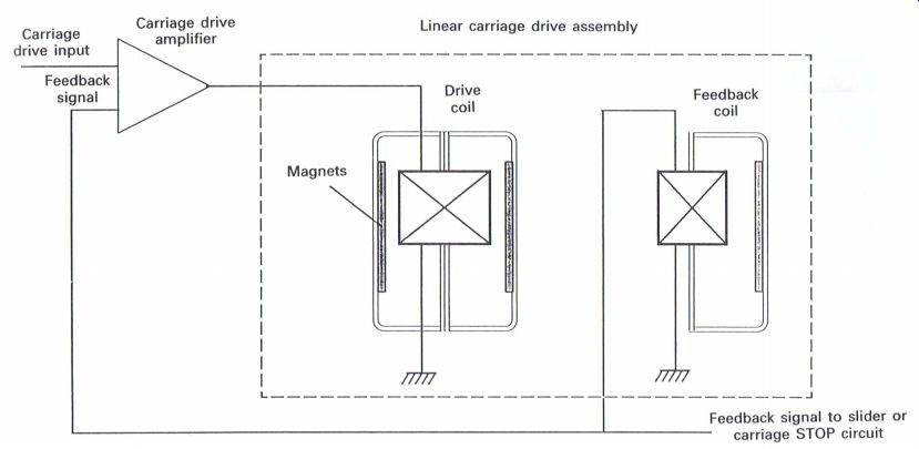
Figure 4.21 Linear drive carriage systems edge of the disc, the disc will
slow down as it maintains a constant linear velocity (CLV) of 1.21.4 m
s^-1, which in effect is maintaining a constant data rate from the disc.
A crystal oscillator is required to provide a reference that can be compared with the data from the disc to obtain the required signal output which will enable the spindle motor circuit to maintain the correct speed. The spindle motor cannot maintain an absolute correct speed, due partly to disc and motor inertia as the disc naturally slows down during the playing process, but also because it is not essential to maintain an absolute exact speed.
In fact the disc speed will be slightly varying either side of the necessary speed to achieve the required linear velocity of 1.2-1.4 m s^-1, in order to maintain the correct level of digital data from the disc in the RAM. The absolute stability of the CD system of 'virtually immeasurable wow and flutter' is achieved by processing the data through the RAM, which is controlled by the reference crystal source, and any possible wow and ?utter is now related in terms of crystal oscillator stability, which can be measured in parts per million.
Essentially the reference crystal oscillator is the 'master reference' with respect to the overall operation of the spindle servo. In most CD players the disc will commence spinning once the laser has been switched on and focus has been achieved.
The system control circuit will 'kick start' the motor, via the MON (motor ON) signal, and as the motor gathers speed there will be a period during which the effective data rate coming from the disc as the EFM signal will approach 4.3218 MHz.
The EFM information is passed to various sections shown in Fig. 4.22. One particular path is via a phase comparator to enable a VCO to produce an output frequency of 8.6436 MHZ, which is twice the effective frequency from the disc, to enable improved frequency lock and stability of the VCO.
The VCO frequency is divided by two to produce the CD clock frequency, which is passed to the VCO timing circuits to produce two frequencies of 612.5 Hz and 1.8375 MHZ. At the same time the 'master reference' frequency of 8.4672 MHz is passed to the crystal oscillator timing circuits to produce the same two frequencies. The higher frequency of 1.8375 MHz is used to control the rough speed of the motor, whilst the lower frequency of 612.5 Hz becomes the phase or fine speed control.
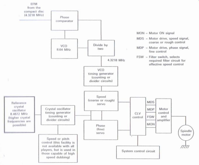
Figure 4.22 Spindle servo system (the early Pioneer in-car CD players
CDX-I and CDX-PI)
--------------------
The outputs from the coarse and fine servos are passed to the CLV control and then on to the motor control to provide the necessary signals to drive the spindle motor at the correct speed. The MDS and MDP provide the required motor speed and phase signals, with the MON providing the motor on/off control. The WSW signal controls the operation of a filter circuit within the motor drive circuit to enable its sensitivity to he varied, with a lower sensitivity whilst the motor is running up to speed, and a higher sensitivity once the motor has achieved the correct speed during normal playing of the CD to provide improved motor control.
As the data are extracted from the disc, and as the initial processing takes place of identifying the sync. signal and converting the 14 bit symbols back into the original 8 bit words, the restructured 16 bit words are fed to the RAM for the purpose of error correction and re-assembling the data words back into their correct order.
Within the RAM there are defined upper and lower limits of acceptable data storage, identifiable by the RAM address lines. Should the storage fall below the lower acceptable level the disc is momentarily increased in speed, to effectively top up the RAM to within the accepted limits.
Likewise as the upper limit is reached then the disc speed is momentarily decreased to prevent overloading the memory with subsequent loss of information.
This fractional variation in speed is achieved by altering part of the dividing function within the crystal oscillator timing circuit to slightly alter the phase servo control and slightly increase or decrease the speed accordingly.
As previously mentioned, the spindle motor suffers excessive wow and flutter, but this is effectively corrected as the data are clocked through the RAM at a rate linked to the crystal reference oscillator, the stability of which may be measured in parts per million.
------------------