The majority of CD players require a series of mechanical and electrical adjustments to ensure optimum operation of the player.
Mechanical adjustments are usually related to the optical assembly whilst the electrical adjustments will be either for the laser power, the servo systems or the VCO.
Any mechanical adjustments will normally only be required to be undertaken when an optical assembly is replaced. With some players these adjustments are either none or minimal, whilst with others there can be quite an involved procedure.
The electrical adjustments will again vary in how many there are and, like the mechanical adjustments, their complexity will usually relate to the type of CD player as well as the manufacturer.
To be able to achieve the correct completion of any adjustment procedures a practical range of tools and certain essential items of test equipment are necessary.
Tools Whilst it is not the intention to teach granny to suck eggs, and the majority of engineers will be in possession of a comprehensive range of tools, it is worth mentioning selected items that have been found necessary, based upon experience:
1. A good selection of flat bladed, Philips, Posidriv and Torx drivers, especially the small to middle range of sizes. In particular, a fine flat blade type with a 2.5 mm blade width and an insulated handle, preferably not an instrument screwdriver, for the grating adjustment of many Pioneer optical assemblies.
2. Allen keys or drivers, especially the smaller sizes. Again with many Pioneer players a 1.5 mm ball type of Allen driver with an insulated handle is extremely useful when adjusting the tangential setting on certain models, but more about that later. This particular item is available from RS Components, Part No. 662-670.
3. The usual range of fine pointed pliers, snippers and tweezers, of course, always have their place amongst any engineer's collection.
4. A selection of specialist tools, such as grating drivers and height gauges as recommended by manufacturers in their relevant service manuals, will be necessary in order to achieve success with some specific mechanical adjustments.
5. Test CDs, of which many types are available.
Reference to the various service manuals will indicate some of the types to be recommended.
These will include the Sony YEDS7, YEDSl8 or YEDS40, as well as Philips' and Technics' own test discs. A favorite of the author is the Pierre Verany Digital Test (Ref. No. 788031) 7 a twin disc set of French origin.
Recommended test discs at reasonable prices do appear from time to time in various hi-fi magazines, and will no doubt be useful as test discs, but there is an important factor to consider when obtaining a disc that is to be used when checking or setting up certain areas of a CD player; this is related to laser power and the amplitude of the RF eye pattern waveform. Whilst conventional music discs fulfill the majority of requirements for the engineer to effectively service a CD player, the quality of the reflectivity of the disc, though not necessarily apparent to the naked eye, can vary from disc to disc, and whilst many engineers' favorite 'test discs' may well suffice for the majority of servicing requirements, it is essential to have a known acceptable standard from which laser power and RF eye pattern can be determined. More on this subject will be given under the areas on laser power and RF eye pattern amplitude.
Other than recommended test discs, and the engineer's favorite discs, whether scratched or otherwise, another type of disc is an 8 mm disc with a maximum playing time of 20 min, which may take some searching for as they do not seem to be readily available, but they do prove extremely useful with respect to certain types of player.
Test equipment
A minimum range of test equipment is absolutely necessary to effectively service CD players, and most of it will be available in the majority of service workshops.
Oscilloscope
The oscilloscope is the most important (and the author's favorite) item of test equipment when it comes to CD player servicing. A twin beam with a minimum bandwidth of 20 MHZ is recommended, though some service manuals suggest a minimum of 50 MHz. A pair of ><10 probes will also prove necessary to minimize unnecessary 'loading' of frequency conscious circuits.
Multimeter
A general purpose digital or analog type of multimeter will be adequately effective, though the author, now becoming somewhat aged in years, has a preference for the ancient analog type.
Laser power meter
A laser power meter can prove to be an unnecessary luxury as laser power can usually be determined by the use of a recommended test disc and obtaining a specific RF eye pattern amplitude.
With some players measurement of the laser diode current can indicate whether the laser power is within specified limits.
On occasions when the service manual recommends that the laser power be measured with a laser power meter, final adjustment is usually achieved with the RF eye pattern amplitude.
With some players it is not possible or even recommended to adjust the laser power.
Test jigs and filters
Some service manuals recommend specialist jigs and filters of which the jigs are generally used for the purpose of servo gain adjustment, and the filters to minimize noise when monitoring certain waveforms.
As the jigs, wherever recommended, will generally differ from one CD player manufacturer to another, many engineers have frequently determined methods of successfully completing adjustments without jigs, due in the main to their cost as well as their limited availability.
Concerning filters, the author has found that monitoring relevant waveforms without filters has not impeded the required result from the related adjustment.
Further comments will be made concerning these items as suggested procedures are outlined for relevant adjustments.
Test or service modes
Before proceeding with any adjustments, it may well prove necessary as well as useful to determine whether a specific CD player has some form of test mode, which will no doubt assist engineers in servicing these units. Of course, reference should be made to the relevant service manuals.
The test or service mode can also be extremely useful when it is necessary to carry out fault diagnosis on CD players.
To highlight the facilities available with the test or service modes, the methods adopted by Pioneer and Philips will be outlined, but there are other manufacturers that have either a limited facility or have introduced more extensive facilities in recent years for which further information can be obtained in relevant service manuals.
It is, however, possible to achieve reasonable success in many of the adjustments with CD players that do not incorporate any form of test mode facility.
Pioneer test mode procedures (Fig. 6.1)
With Pioneer CD players the test mode is selected by either depressing a special non-latching test button, or shorting two links marked 'test,' either of which will be found on the main PCB, and applying the mains supply.
As with many products the mains supply will either be controlled via a mains on/off switch, or be applied directly to the mains transformer, on/ off control being determined by a standby switch in conjunction with the system control. There fore the two options to achieve the test mode will be as follows.
1. Players with mains on/off switch depress test switch or short test links
. switch on mains supply switch count to three to ensure test mode is achieved
. release test switch or short to the test links
. the front panel display should have minimal illumination
09-06:
If the illumination appears normal, the player is probably not in the test mode: repeat the above sequence.
2. Players with permanent supply to the mains transformer
a. depress test switch or short test links
b. apply the mains supply
c. count to three, to ensure test mode is achieved
d. release test switch or short to the test links
e. switch on the standby or on switch
f. the front panel display should have minimal illumination
If the illumination appears normal, the player is probably not in the test mode: repeat the above sequence.
Philips service mode procedures
To achieve the service mode, the methods for three particular models will be outlined:
CD150. Simultaneously depress the following keys: PREVIOUS, NEXT and TIME/ TRACK.
CD582. Simultaneously depress the following keys: SEARCH, PAUSE and REPEAT.
CD840. Simultaneously depress the following keys: NEXT and PLAY.
Now switch on the mains supply, and count to three before releasing the three keys, to ensure that service mode is achieved. This is the standby mode, and '0' will appear on the display. In this condition it should be possible to move the radial arm from one extreme to the other by depressing the 'Search FWD' and 'Search REV' keys.
Further stages in the service mode can be achieved by subsequent depressions of the NEXT key.
Service position
1. With no disc inserted Depress the NEXT key. The laser will switch on, and the focus lens will move vertically 16 times before stopping; the player will revert to the standby mode.
With a disc inserted
Depress the NEXT key. The laser will switch on, and the focus lens will achieve focus. When this has been achieved, '1' will appear on the display.
Service position
2. Depress the NEXT key. The turntable will commence rotating, and '2' will appear on the display.
Service position
3. Depress the NEXT key. The radial control servo is switched on, and '3' will appear on the display.
Providing the radial arm is within the music area of the disc, sound output should be achieved.
The service mode is cancelled when the player is switched off.
Adjustment procedures
The range of adjustments, electrical and mechanical, that are necessary can vary between ranges of models as well between different manufacturers. Whilst each method of adjustment will be described, it should be emphasized that not all the listed adjustments will appear at the same time in one player--much to the relief of many engineers, no doubt.
Unfortunately with CD players a range of pre set controls for adjustment purposes often provide a 'tweaker's paradise', and random adjustment can often provide further problems, some of which may appear quite catastrophic.
Test mode and adjustment procedures
Electrical adjustments
There are a wide range of adjustments, and when they are carried out, those that are relevant to a particular player should be implemented in the order listed below, unless otherwise recommended, in order that optimum results may be achieved:
1 focus offset
2 tracking offset
3 RF offset
4 laser power
5 tracking balance
6 focus balance
7 focus bias
8 photo-diode balance
9 RF level
10 focus gain
11 tracking gain
12 VCO frequency
Mechanical adjustments
The following range of adjustments will not necessarily appear in all players, but again there is a recommended sequence with respect to particular players.
1 turntable height 2 tangential adjustment 3 lateral adjustment 4 diffraction grating adjustment
Methods of electrical adjustment
If a CD player has been incorrectly adjusted at some stage, frequently during fault diagnosis, it is "often worthwhile to look at the settings of the electrical adjustments. Generally the majority of these adjustments will be near to the center of the range of the adjustment setting when the player is operating normally; if any of the presets are virtually at one extreme then the possibility exists that there is an additional 'man-made' problem in addition to the original fault. With the exception of the laser power and also the VCO presets, all other presets can usually be set to their mid-point before the adjustment procedure is commenced.
Essential oscilloscope checks
Before commencing any electrical adjustment or measurement with an oscilloscope, it is essential that the calibration of the oscilloscope (especially the 10:1 probe) is checked and adjusted as necessary.
Always allow for the 10:1 probe when measuring levels such as the RF eye pattern, and check that if the Y amplifier is set to 50 mV in reality, 500 mV will be the value of the actual measurement at the end of the 10:1 probe.
Also, and again never wishing to 'teach granny to suck eggs' when measuring offset potentials, always ensure that the input selector switch is set to do. Though this may seem obvious, it has always proved interesting on the many technical training courses attended by the author, how many oscilloscopes are set to ac, where of course if the trace is set to zero, any adjustment to the offset control always returns to zero after any movement of the preset!!! One final point is worth mentioning: if measurements of waveforms are being monitored with the input selector set to a.c., ensure that the internal input capacitor of the oscilloscope is discharged, by just grounding the tip of the probe.
Otherwise any voltage charge in the capacitor from one measurement can be carried across to a voltage sensitive area, and a few laser beams have been known to 'disappear' through a nasty short sharp shock from the end of a 'scope probe.
Focus offset adjustment
As with all servo systems, it is necessary to minimize undesirable d.c. potentials within the system to ensure that it operates with optimum efficiency (Fig. 6.2). If this adjustment is not correctly observed then problems such as the inability to focus, skipping or jumping can occur.
The oscilloscope is connected via a 10:1 probe to the focus error (FO ER) test point, or equivalent, and the focus offset adjusted to neutralize any voltage or set to the manufacturer's specifications.
The player does not necessarily have to be in the test or service mode and, unless specified, a disc is not inserted.
Examples of some different manufacturers' procedures are detailed below.
-----------------------------
Key functions in the TEST MODE Key functions in the TEST MODE
Switching OFF the player, or removing the mains supply releases the player from the test mode
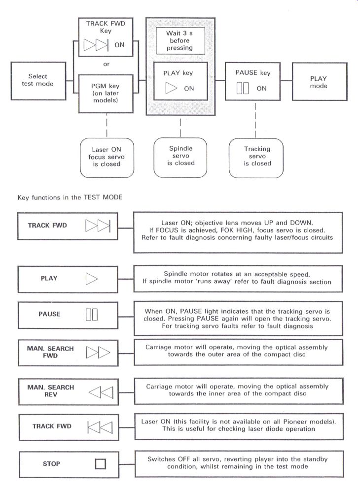
Figure 6.1 Test mode procedures (Pioneer)
Laser ON; objective lens moves UP and DOWN.
lf FOCUS IS achieved, FOK HIGH, focus servo Is closed.
Refer to fault diagnosis concerning faulty laser/focus circuits
Spindle motor rotates at an acceptable speed.
If spindle motor 'runs away' refer to fault diagnosis section
When ON, PAUSE light indicates that the tracking servo is closed. Pressing PAUSE again will open the tracking servo.
For tracking servo faults refer to fault diagnosis
Carriage motor will operate, moving the optical assembly towards the outer area of the compact DISC
Carriage motor will operate, moving the optical assembly towards the inner area of the compact disc
Laser ON (this facility is not available on all Pioneer models).
This is useful for checking laser diode operation
Switches OFF all servo, reverting player into the standby condition, whilst remaining in the test mode
-------------------------
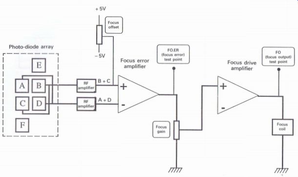
Figure 6.2
Basic focus servo
Philips players
Not all Philips players have a focus offset, the CD150 being one of these. The section of circuit shown in Fig. 6.3 relates to the CD840 and is similar to that in other models containing this adjustment.
1 The oscilloscope is connected via a 10:1 probe to the FE LAG connection, usually referred to as Test Point 27.
2 The player is switched on with no disc inserted.
3 The focus offset is adjusted for the optical mid-position of the objective lens.
4 Now the test disc is played and the focus offset is adjusted until 400 mV is obtained at Test Point 27.
Pioneer players
With the Pioneer players, variations in the value of the offset potential can be experienced depending upon which type of optical block is fitted, and in some instances whether the player is a single disc type with the objective lens facing upwards, or a multiple disc player, or even the stable platter single disc type where the objective lens faces downwards (see Fig. 6.2).
1 The player is switched on. For this adjustment the test mode is not essential, and no disc is inserted.
2 Connect the oscilloscope, via a 10:1 probe, to the FO.ER or FCS ERR. test point, depending upon the model.
3 Adjust the focus offset until the following level is achieved in relation to the optical block that is fitted:
PWY1003 to PWYIOll 0 V PEA1030 (single disc and twin tray players)--50 mV PEA1030 (multi-disc players) -150 mV PEA1030 (single disc stable platter players) -150 mV PEA1179 (see below) 0 V
Note: The PEA 1179 is the new Pioneer optical block fitted to some of the most recent players, and is also referred to as the '92 Optical Block.
This particular optical block is supplied with a small PCB attached with some small preset controls which are factory set, and therefore are not recommended for any adjustment. With this optical block the focus offset is verified to be at the zero level.
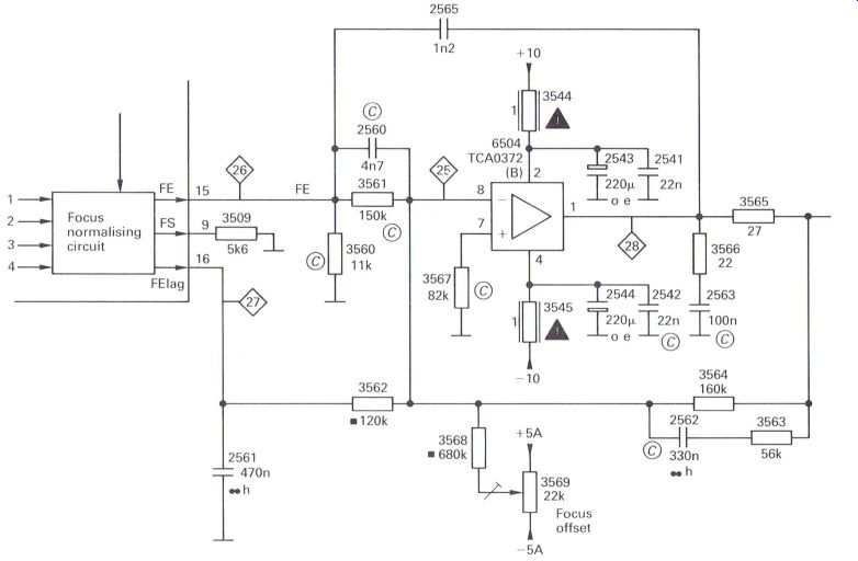
Figure 6.3 Philips focus offset
Other players Not all players have the focus offset adjustment, but many of those that do have this adjustment fall into one of three categories:
1. The player has a radial optical assembly, and the procedure outlined for the Philips players will usually provide an acceptable method (Fig. 6.3).
The Sharp DX-361 and Technics SL-Pl 1 1/7 fall into this category, and are identical in achieving the correct focus offset.
2. Unless otherwise specified in the relevant service manual, the offset control is adjusted to 0V as outlined for the basic servo above.
3. The offset preset is set to the mid-position, the disc is played, and whilst monitoring the RF eye pattern with an oscilloscope the focus offset is adjusted for the clearest waveform to ensure that optimum adjustment is achieved.
With reference to 3 above, it can frequently prove useful to monitor either the RF eye pattern waveform, or the focus error waveform, which is in effect a 'noise' waveform, and to carefully adjust the preset to optimize either waveform. This in effect is 'fine tuning' the focus coil in the optical block to the servo system and can occasionally assist in endeavoring to overcome some 'skipping' and 'jumping' problems that have a tendency to occur.
Further reference to the fault diagnosis section will provide further information regarding these type of problems.
Tracking offset adjustment
Similar to the focus offset adjustment, the objective is to remove unnecessary d.c. potentials that would otherwise affect the operation of the tracking servo (Fig. 6.4).
Generally, for those players that have the
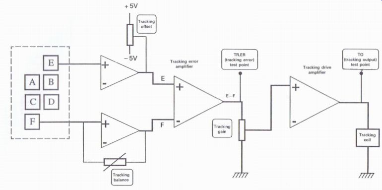
Figure 6.4
Basic tracking servo tracking offset adjustment the procedure is quite straightforward:
1 Connect the oscilloscope to the tracking error test point (TE 0r Tr Err) or equivalent.
2 With the player switched on, and no disc inserted, adjust the preset for 0 V as accurately as possible.
It is possible to obtain a fine adjustment by playing a disc and monitoring the RF eye pattern waveform, and carefully adjusting the preset for the clearest waveform, which will be the point of Virtual maximum amplitude.
RF offset adjustment
This adjustment is not present in many players but was necessary in a range of Pioneer models (Fig. 6.5), and also in the early Sony models such as the CDP-101.
The adjustment is carried out by switching on the player, with no disc inserted.
1 Monitor the RF test point:
Pioneer players: TP1 pin 1
Sony CDP-101: TP3 2
Adjust the RF offset for:
Pioneer players: 100 mV
Sony CDP-101: 1.35 V
Laser power adjustment
Not all players have the facility of laser power adjustment, and even if there appears to be a method of altering the laser power, care should be taken as experience has shown that when a laser diode has aged increasing the power of an apparently weakened laser beam can more often as not hasten its final demise.
Usually the laser power is only adjusted when an optical assembly is replaced, and the level will normally be maintained by the automatic power control circuit.
Antistatic precautions
Though all replacement optical blocks have some form of static protection, it is recommended that normal precautions are taken to avoid static electricity damage when handling optical blocks as well as many of the integrated circuits used in many of today's sophisticated electronic products.
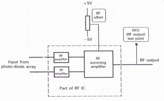
Figure 6.5 RF offset adjustment
Figure 6.6 Laser warning diagram
These precautions can involve body and work» bench grounding facilities, as well as the minimal use of clothing subject to static.
Precautions concerning laser beams
With respect to laser beams themselves, care should be taken if deciding to view the laser beam when endeavoring to determine whether the laser diode is functioning (see Fig. 6.6). Ideally laser beams should not be viewed, as the majority of the power is invisible and the frequency at which the laser operates is within the infra-red spectrum, so all that can normally be seen is usually a faint red spot of light.
For many engineers the quickest method of determining whether a laser is functioning is in fact to actually View its emission from the objective lens. If this is the chosen method then applying a few basic rules will minimize any problems.
1 Ensure that the laser beam is low power, and in the case of CD players this power is usually no more than 250 uW with many players operating at around 120 uW.
2 Maintain a minimum distance between the lens and eye of 30 cm.
3 Do not View the lens directly, but slightly to one side.
4 Do not view the laser for more than 10 s.
(After all is said and done, how long does one have to View an ordinary lamp before deciding that it is switched on?) Generally the laser power only requires adjustment when an optical block is changed, and then only if it is possible and recommended. Many replacement optical blocks come with the laser power factory-set, and therefore do not require any further adjustment.
Test mode and adjustment procedures
As previously mentioned, the initial setting of the laser power with a laser power meter is usually finalized by monitoring the RF eye pattern waveform for the correct amplitude. Many service departments do not possess a laser power meter--or if they do, it often becomes a redundant piece of test equipment. Furthermore, access to monitor the laser can prove difficult with some CD players.
The author's preferred method is to monitor the RF eye pattern waveform for the correct amplitude, but there is merit in measuring the laser current: in order to determine the laser power.
Examples of some different methods recommended by different manufacturers will be high lighted as follows, but further information is available in the relevant service manuals and other supporting technical information frequently supplied by manufacturers.
Philips players
The recommended procedure for the CD150 (which is similar to other Philips models) is to measure the voltage across a resistor which is the result of the power of the laser beam reflected from the CD onto the photo-diode array (Fig. 6.7).
1 Insert a recommended test disc.
2 Set the laser power control to the mid-point setting (if the optical block has been replaced).
3 Put the player into service mode 1 (laser will be on and in focus).
4 Monitor the voltage across test points 1 and 2.
Adjust the laser power control to obtain 40 mV (this is a preliminary adjustment).
5 Play the disc.
6 Adjust the laser power control to obtain 50 mV across test points 1 and 2.
Pioneer players
The player will need to be put into the test mode, and a test disc inserted (refer to Figs 6.1 and 6.8).
1 Select TRK FWD or PGM (program) depending upon the model of the player, followed by PLAY after ~3 s; the disc should now rotate at a reasonable speed.
2 Monitor the RF test point to determine the peak-to-peak value of the 'blurred' eye pattern waveform. (The reason for observing a 'blurred' eye pattern is that the disc cannot be played correctly if the grating adjustment is incorrect when replacing an optical block, or if someone else got there first and adjusted it incorrectly) (Fig. 6.9).
3 Adjust the laser power control (usually VR1) until the following peak-to-peak value is obtained depending upon the type of optical block fitted:
PWY1003-PWY1011 5 V PEA1030 1.2 V PEAl 179 1.2 V (see Note below)
Note: The PEA 1179 is the new Pioneer optical block fitted to some of the later range of players, and is also referred to as the '92 Optical Block.
This particular optical block is supplied with a small PCB attached with some small preset controls which are factory set, and therefore are not recommended for any adjustment. As will be high lighted elsewhere, this optical block minimizes the number of adjustments in the relevant players to which it is fitted.
A final check of the laser power is made on completion of all other adjustments to ensure that the recommended level is still maintained when a disc is being played, and some final adjustment may prove necessary.
Sony players
With Sony optical blocks details are usually supplied with each optical block concerning specified laser power current.
The information is given on a label fixed to the block, and examples of these are given in Fig. 6.10.
Specification limits are: the current value printed on the label + 11 mA to -5 mA at 25°C.
As a laser ages the current will increase, and if the current exceeds the specified limit, the optical block should be replaced. Any attempt to adjust the laser power will usually hasten its demise.
JVC players
Adjustment is similar to the Sony method described above. An example detailed in a IVC service manual may prove of interest to engineers.
When the life of the laser has expired the following symptoms will appear:
1 The level of the RF eye pattern waveform will be low.
2 The drive current required by the laser diode will be increased.
See Fig. 6.11.
Measurement of laser diode current
With reference to Fig. 6.12, open the relevant link and insert a 1 ohm resistor. With the laser diode operating, monitor the voltage across the ...
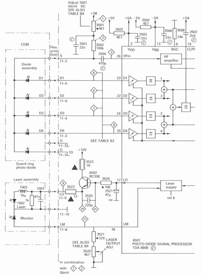
Figure 6.7 Philips laser power adjustment
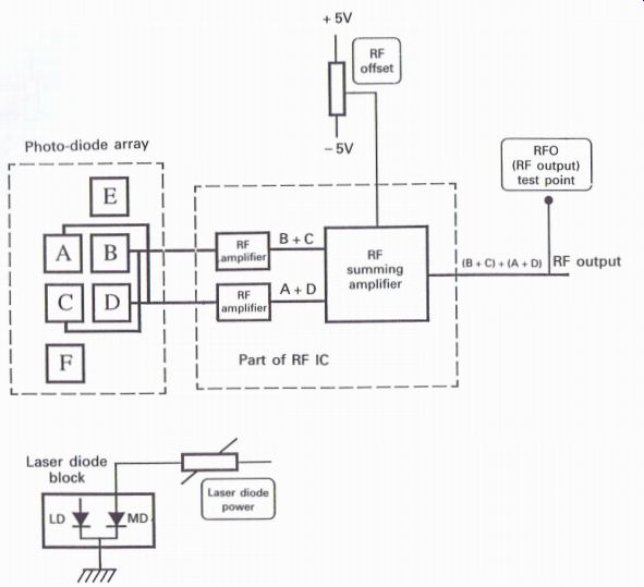
Figure 6.8 Pioneer laser power adjustment
... resistor. If the voltage is excess of 120 mV (which is equivalent to a current of 120 mA), the life of the laser diode has expired, and it should be replaced.
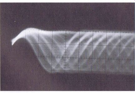
Figure 6.9 Blurred RF eye pattern waveform
A preset may be present on the APC board, and if this adjusted to increase the eye pattern level, the laser diode will again most certainly achieve an early demise.
Comparison of RF eye pattern levels Ideally the eye pattern waveform should be as clean and in focus as possible (as shown in Fig. 6.13). With reference to a wide range of service manuals from different manufacturers, the peak-to-peak levels of the RF eye pattern waveform shown in Table 6.1 may prove a useful guide. All measurements were achieved with the use of a test disc.
The information in Table 6.1 is intended as a guide across a wide range of players, but absolute verification should be obtained from the relevant service manual wherever possible. Whilst most manufacturers quote a tolerance range, the author
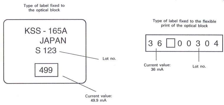
Figure 6.10 Example of Sony laser current label
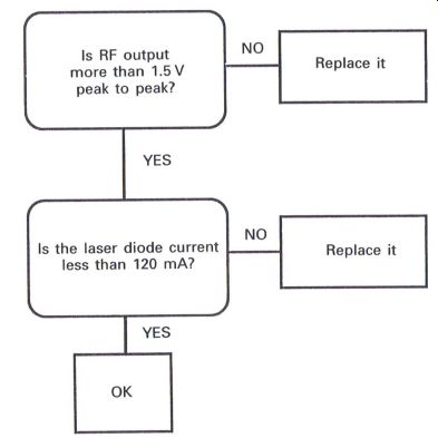
Figure 6.11 JVC flow chart: the life of the laser diode prefers to maintain
the center of the quoted tolerance wherever possible.
Tracking balance adjustment
Tracking balance adjustment is present in many players and its purpose is to ensure that the gains of the tracking signal amplifiers are identical before the signals are applied to the tracking error amplifier to produce the tracking error signal. In order that this adjustment can be carried out it is necessary to prevent the tracking servo (Fig. 6.4) from fully functioning. There are three methods of achieving this.
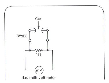
Figure 6.12 JVC laser diode current measurement
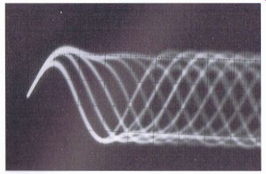
Figure 6.13 RF eye pattern waveform Table 6.1
I. If the player has a test or service mode facility adjustment is carried out with disc inserted and rotating, with the laser on and the focus servo operating, but with the tracking servo off. The example previously explained relating to the Pioneer players is briefly repeated below, but it will be necessary to determine the same functions in other players to achieve the same results by referring to the service manual. The Philips and similar players (i.e. with the radial tracking method) do not have the tracking balance facility, as the gain level of each tracking signal line is automatically determined and adjusted as necessary.
1 Select the test mode.
2 Move the optical block to the center of the playing area of the inserted test disc.
3 Connect the oscilloscope, via a 10:1 probe, to the tracking error test point (TE or TRK ER) or equivalent.
4 Press 'TRK FWD' (or PGM). The laser and focus servo circuits should become operational.
5 After 3s press 'PLAY'. The disc should now rotate at a reasonable speed.
6 Adjust the tracking balance preset until the resultant waveform is balanced either side of the zero line.
2. If no test mode facility is available, it Will be necessary to disrupt the tracking servo circuit.
1 First insert and play the test disc, and select a track near to the center of the playing area of the disc.
2 Connect the oscilloscope, via a 10:1 probe, to the tracking error test point (TE or TRK ER) or equivalent.
3 Now turn the tracking gain control to
4 Adjust the tracking balance preset until the resultant waveform is balanced either side of the zero line, as illustrated in Fig. 6.14.
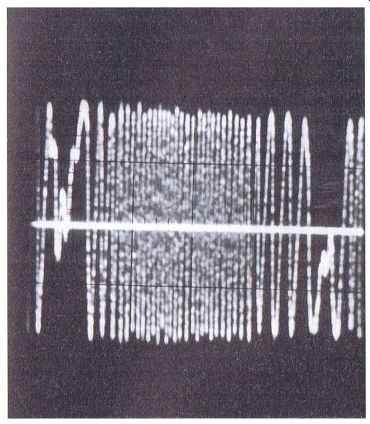
Figure 6.14 Tracking balance waveform minimum, taking note of the original
position of the control before proceeding.
Due to the tracking gain control being turned to minimum, the player may appear to object to this procedure, and it may eventually stop operating, but there is usually sufficient time to carry out this operation successfully.
On completion, restore the tracking gain control to its original position.
3. Alternative method if there is no test mode; this method can also be applied to players with a test mode.
1 First insert and play the test disc, and select a track near to the center of the playing area of the disc.
2 Connect the oscilloscope, via a 10:1 probe, to the tracking error test point (TE or TRK ERR) or equivalent. The oscilloscope will display the standard tracking noise type of signal.
3 Now press the manual search FWD or manual search REV keys. The lens will gradually track across the disc, and during this process a tracking error waveform will 'ghost' behind the tracking noise waveform.
4 Adjusting the tracking balance control until the 'ghosting' waveform is balanced either side of the tracking noise waveform.
Automatic check of the tracking balance adjustment
A limited number of players have an automatic facility of adjusting the tracking balance, one in particular being the Pioneer pD-8500, which contains a Toshiba TC9220F digital servo processor.
With the player in the test mode, as previously described, and the oscilloscope connected to the tracking error test point, set the oscilloscope to the center of the screen. There will be a positive potential of approx. 2 V at this point, which amazingly is quite normal.
With a test disc inserted, press 'TRK FWD', followed by 'PLAY'. Three seconds later, the tracking balance waveform will be observed on the oscilloscope.
Now press the 'REPEAT' key; the waveform should balance either side of the center line.
The purpose of this check is to verify that tracking balance can be achieved, as this is an automatic procedure which is carried out each time a disc is played, and is in fact one of four automatic sequences that are carried out whenever a disc is played, the others being the automatic adjustment of the focus offset and the focus and tracking gains.
Focus balance, focus bias, photo-diode balance adjustments
The above adjustments will appear in various players, but not all in the same player, with the procedure for any of the adjustments being identical even though each of their functions may well be different.
1 Insert and play the test disc, and select a track near to the center of the playing area of the disc.
2 Connect the oscilloscope, via the 10:1 probe, to the RF test point to monitor the RF eye pattern waveform.
3 Play the test disc, and adjust any of the relevant controls until the eye pattern waveform appears to be at its maximum amplitude, consistent with being as cleanly in focus as possible.
RF level adjustment
RF level adjustment is usually found as a specific preset control in the earlier players, and wherever possible reference should be made to the relevant circuit diagram. However, many later players, such as Pioneer, verified that the RF level was correct by adjusting the laser power (refer to the section on laser power adjustment), whilst playing a recommended test disc, to achieve the recommended level as detailed earlier in this section under the heading ‘Comparison of RF eye pattern levels'.
Focus and tracking gain adjustments
Some players do not have focus and tracking gain controls, but for those that do there are various methods of carrying out these adjustments. These are described in the relevant service manuals, and can involve additional test equipment, some of it being specialized.
Generally these methods will require an external audio frequency source, special filters together with the oscilloscope, and eventually adjustment of the relevant gain control to achieve the required Lissajous waveform.
Engineers who wish to pursue this method of gain adjustment should refer to the relevant service manual for the player involved.
Though the adjustment of these controls is relatively critical, there will still be a reasonable margin of tolerance in their adjustment, and if either adjustment proves to be extremely critical then the possibility of a fault condition must be considered.
Many engineers have adopted a method of using a tried and tested 'ever faithful' disc which has fine scratches over the surface as a result of possible mis-use over a period of time. 'If it plays that, it will play anything' is the comment frequently heard, and this does prove to be a method with a fair amount of merit.
Unfortunately players do vary in overall quality, with some having optical blocks that appear to be more noisy than others, thus creating an impression that maybe the focus and tracking gain is high and generating excessive noise, whilst the less noisy optical blocks can create the impression of low levels of gain.
Ideally, neither of the gain controls should be touched; they should be kept in their factory-set positions, which in fact will usually be near to their mid-point position. Therefore if the required test equipment is not available, and in times of servicing expediency, setting both presets at around their mid-point setting or just a fraction less will generally be quite an acceptable measure.
Occasions have occurred where the author has set up all the equipment described in the service manual and followed the procedures by the guide, including the filters and the recommended test disc, and where, on completion of the procedure where the required Lissajous waveform was as recommended in the service manual. And where were the two controls? ... well blow me down... they are just before the mid-point position, and it took twenty minutes to discover that! The author, when visiting a production line where different models of CD players were being manufactured, made an observation of the focus and tracking gain presets after following the factory procedures outlined above to maintain the required specification, which indicated consistently exactly the same position of just before the midpoint. Of course, it was appreciated that these were brand new players of the same manufacturer.
As a result, the author has preferred not to use the involved methods described and has tended to follow a more simple approach, which is not of course intended to detract from any of the methods that are recommended by various manufacturers to achieve optimum effectiveness.
Focus gain adjustment Play the test disc, preferably with minimal or no scratches, and monitor the focus error (FE) waveform with an oscilloscope via a 10:1 probe.
Select a track near to the central playing area of the disc. As the gain adjustment is increased, so will the noise being monitored on the oscilloscope.
Two possible options can be achieved when the focus gain preset is altered:
1 an overall noise amplitude of no more than 500 mV, or 2 the center line d.c. level of the noise at about 100 mV.
As the gain is reduced, the d.c. level will tend to increase and the waveform will tend to bounce due to insufficient gain, whilst increasing the gain will certainly increase the noise level.
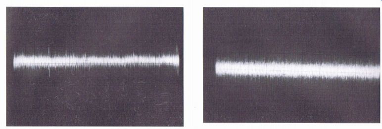
Figure 6.15 Focus error waveform
Both of the above results have been observed in some service manuals, and still maintain the consistency of the control being set to just before the mid-point.
Another option is to listen to the acoustic noise that comes from an optical block whilst a disc is being played. As the gain is increased, the acoustic noise will increase, and will naturally decrease with the reduction of gain. Providing this method is carried out in a quiet environment it is possible to get the 'feel' of different players whilst adjusting the control for an acceptable relatively faint level of noise that still enables the control to be around the mid-point level.
Tracking gain adjustment
Tracking gain adjustment is probably more important than focus gain, especially if the player is susceptible to skipping and jumping, and it is possibly easier to achieve a more effective setting.
1 Monitor the tracking error (TE) waveform (Fig. 6.16) with an oscilloscope, via a 10:1 probe.
The noise level will normally be higher than for the focus error, and is usually centered on the zero potential line.
2 Increase the tracking gain until a frequency becomes apparent amongst the noise; this is the natural servo frequency. Note the position of the control at which this frequency becomes apparent.
3 Reduce the gain until the waveform now begins to bounce up and down. Again, note the position of the control when this becomes apparent.
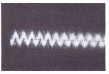
Figure 6.16 (a) Typical tracking servo noise, normal (1)) Excessive tracking
gain
4
Set the control midway between these two points; usually this will be just before the midpoint position.
The procedure outlined regarding acoustic noise for focus gain can also be adopted to achieve similar results. Optical blocks tend to vary in the amount of acoustic noise they emit and thus this method should be treated with caution especially if a particular type of optical block tends to be more noisy when compared to others.
Voltage controlled oscillator (VCO) frequency
If the VCO frequency is not correct, it is possible that the disc will not play, or that it may suffer from intermittent audio output.
It is usually preferable to use a frequency
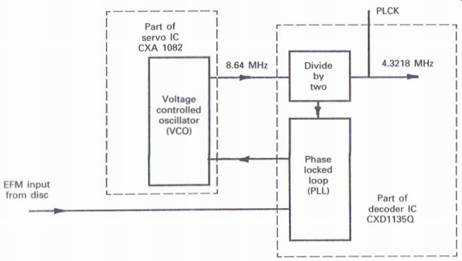
Figure 6.17 VCO block diagram counter, and ensure that the free run VCO
frequency is set to the recommended setting, which may be in the region
of 4.3 MHZ or 8.64 MHZ, depending upon where in the circuit the VCO frequency
is being monitored (Fig. 6.17).
When a disc is being played correctly, the VCO circuit will usually operate at a frequency of twice the disc clock frequency of 4.31218 MHZ, (i.e. 8.62436 MHZ), which is divided by two to produce the required resultant clock frequency.
The majority of players will usually refer to the lower frequency, and the author's preference is usually to set the VCO free run frequency at around 4.375 MHZ, without inserting a disc, and not in the test mode.
It may prove necessary to verify from the service manual the relevant point to which to connect the frequency counter, usually Via a 10:1 probe, and also to ascertain whether the phase locked loop (PLL) has to be disabled by shorting two links, such as in Pioneer players by connecting together the asymmetry signal line (ASY) and ground (GND).
The reason for choosing 4.375 MHZ is to en sure that the VCO is running at a frequency higher than the required 4.3218 MHZ to assist in a possibly more efficient capture range as the disc runs up to speed at the commencement of play.
Another method, especially if a frequency counter is not available, is to observe the VCO frequency on an oscilloscope, again via a 10:1 probe, whilst a disc is being played, and to adjust the VCO frequency adjustment in one direction until the waveform begins to jitter and then to adjust back in the opposite direction until jitter occurs again, then to set the control to the position midway between the two points where the jitter occurs.
The foregoing completes the majority of electrical adjustments that may be found in CD players, and now it is necessary to consider the relevant mechanical adjustments.
Mechanical adjustments
Generally mechanical adjustments are only necessary when an optical block or spindle motor has been replaced, or some other mechanical servicing has been necessary within the optical assembly.
Many optical blocks do not require any major adjustments when they are replaced, whereas others, such as those in many Pioneer players, require an extensive and involved procedure to be carried out; to the un-initiated this may seem overwhelming, whilst many engineers who have trod this path before may consider that the adjustments are more acceptable in the light of experience.
Turntable height
If it has proved necessary to replace a disc, spindle or turntable motor (spindle motor will be used hereinafter), it is essential to ensure that the disc turntable, if it is a removable type, is replaced at the correct height.
Some spindle motors are supplied as an integral component of a complete optical assembly, which is usual with the Philips radial assembly.
Shown below are a range of recommended turntable heights with respect to a range of players. If the height information is not available, and it is necessary and possible to replace the motor, it is recommended that the original turntable height is first observed and measured with a suitable gauge to ensure correct reassembly afterwards.
If the turntable height is incorrect it is possible for the disc to 'bind' within the internal mechanism or scrape on the drawer assembly, with possible damage to the disc. Also, the RF eye pattern waveform can be affected by the height of the turntable, and the focus servo will have to adjust the lens position to suit the incorrect height which could cause inefficiency of the servo operation.
Reference to a wide range of service manuals has shown that some spindle motors are supplied complete with the turntable fitted. Access to the motor fixing screws is through holes in the turntable, and the complete assembly is removed sideways from the mounting plate Via a slot.
In other examples the turntable is bonded to the spindle, which can make removing it difficult;
the bonding material may be softened by the gentle application of heat to the spindle shaft with a soldering iron, and a suitable bonding material is used to bond the turntable onto the replacement motor shaft. The Sanyo MCD-730L is an example of this method.
The Technics SL-Pl l 1 method is illustrated in Fig. 6.18. With this method the turntable height is set to the correct height with a 0.9 mm feeler gauge (Technics Part No. RZZOZ97), and is then fixed to the shaft by a screw tightened with a 1.27 mm hexagonal wrench.
With Pioneer players a height gauge is supplied
Turntable
0.9 mm feeler
0.9 mm gauge
rtnun/"u""annual"
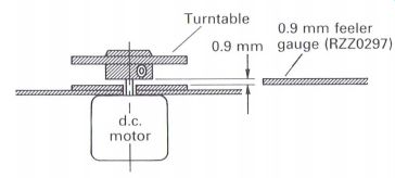
Figure 6.18 Technics turntable height adjustment molded onto the complete
optical assembly unit, as illustrated in Fig. 6.19.
It is necessary to use the correct gauge for the type of player (i.e. single, twin or multi-disc), as the type of turntable and its respective height may well be different for different types of player.
With the later players the gauge molded onto the optical assembly can be observed to be in effect two gauges in one: a thin inner gauge, usually for the single turntable platter and the multi-disc players, and a thicker outer rim for the single and twin tray players.
Earlier players had a single gauge which had a recess on one side to allow for a small amount of protrusion of the spindle motor through the mounting plate.
It is recommended that before removing the spindle motor, the engineer determines and selects which gauge is required, and checks this against the original turntable height.
Removal of the gauge from the molding can be achieved with a pair of fine nippers, ensuring that any burrs are removed.
When refitting the turntable, apply the correct gauge, and gently press the turntable onto the motor shaft, preferably with a base support for the motor, until the turntable rests upon the gauge.
Remove the gauge on completion.
Tangential and lateral (radial) adjustments When an optical block is replaced, some players require mechanical alignment of the optical block to ensure that the laser beam is directed accurately towards the surface of the disc, and in effect the beam is at right angles to the surface of the disc (as illustrated in Fig. 6.20).
If this adjustment is not set correctly, not only
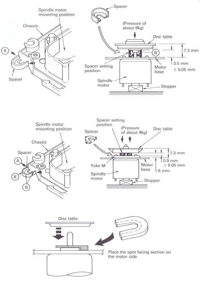
Figure 6.10 Pioneer turntable height gauge locations
Enlarged basic view of the effect of adjusting the tangential adjustment screw (optical block effectively moves in and out of page)
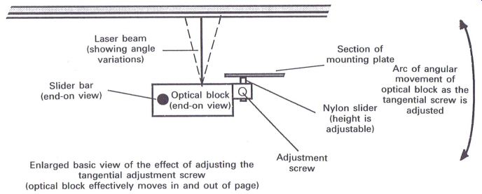
Figure 6.20 ----Angle of laser beam to disc surface will the RF eye pattern
waveform be unsatisfactory, but also the player may be susceptible to skipping
and jumping, and with some players the diffraction grating adjustment will
prove difficult or impossible to achieve correctly.
Because these adjustments are not necessary on all models of players, when an optical block is replaced, the procedures for the Pioneer players provide an excellent basic outline which can be applied as necessary on those models that may require this adjustment to be implemented.
With earlier Pioneer players, i.e. those using the PWYlOll type optical block (Fig. 6.21), the Tangential adjustment Figure 6.21 Pioneer PWYIOII type optical assembly optical assembly requires only the tangential adjustment, but with the later models, using the PEA1030 and subsequent type optical blocks, tangential and lateral (or radial) adjustments are necessary.
This adjustment can be achieved with a 1.5 mm hexagonal wrench, but because access can prove difficult a 1.5 mm hexagonal ball wrench can prove extremely useful, this is available from RS (Part No. 662~670, which is a pack of four different size wrenches), but engineers may know of alternative sources for this item.
Before fitting a replacement optical block it is recommended that the hexagonal screw is initially adjusted to set the small white nylon runner to its mid-point setting, or if the block is being replaced, adjust the new one to the same point by comparison.
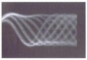
It is necessary for this adjustment to be finally carried out in the test mode as it will be necessary to move the optical block towards the outer edge of the disc until the hexagonal screw can be accessed. By observing the RF eye pattern waveform on an oscilloscope, whilst playing a disc, the hexagonal screw is adjusted until the optimum waveform is achieved (Fig. 6.24).
The recommended procedure is as follows:
1 Set the player to the test mode (refer to the test mode section).
2 Move the optical block until the adjustment screw can be accessed.
3 Insert a recommended test disc.
4 Connect an oscilloscope, via a 10:1 probe, to the RF test point.
Nylon runner
Tangential adjustment (1.5 mm HEX) Figure 6.22 Enlarged section ofPioneerPWYI011 optical block illustrating the tangential adjustment and nylon runner
Figure
6.23 Blurred eye pattern due to poor tangential adjustment
5 Press 'Track Forward' (TRK FWD) or 'Program' (PGM).
6 Press 'PLAY'. The disc will rotate at a reasonable speed.
7 Adjust the tangential screw for maximum amplitude of the waveform.
Note. This waveform should appear as a 'blurred' RF eye pattern. The service manuals will usually illustrate a waveform that can be achieved after the 'PAUSE' control has been pressed when an in focus RF eye pattern will be
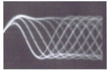
Figure 6.24 Acceptable eye pattern after tangential adjustment achieved.
This adjustment can frequently 'jar' the optical block whilst it is being
attempted, with frustrating effects on the player and engineer alike, especially
if the screw is 'Way out' of adjustment.
The above procedure will minimize these effects, and act as a coarse adjustment; when the 'feel' for this adjustment has been obtained, pressing 'PAUSE' will enable the adjustment to be 'fine tuned', providing the diffraction grating adjustment is correct.
With the later Pioneer players (those that use the PEA1030 optical blocks and subsequent types) there are two adjustments: one for tangential and the other for the lateral or radial adjustment.
Access for the relevant screws is much easier, whether the adjustment is necessary in either single, twin or multi-disc players where the optical blocks can be mounted 'lens up' or 'lens down'.
Fig. 6.24 shows the location of the adjustment points for a 'lens up' optical assembly using a 1.5 mm hexagonal wrench. With a 'lens down' assembly the location of the screws will effectively be the same, but as it is now the other end of the hexagonal screws that are to be adjusted, a small Philips screwdriver will be required. The procedure is as previously described, with the exception that both screws are adjusted in turn until the optimum RF eye pattern waveform has been achieved.
References to the tangential and lateral (radial) adjustments have been related to the relevant service manuals, but the perfectionist studying this guide may well find that the reference to tangential adjustments in the earlier Pioneer players has become somewhat different for later players. In fact it would seem that the term lateral or radial is more correct when applied to the earlier players, and that tangential adjustment is more correct in the later players. This slight disparity is noted, and the author will leave the reader(s) to draw her, his or even their, own conclusions.
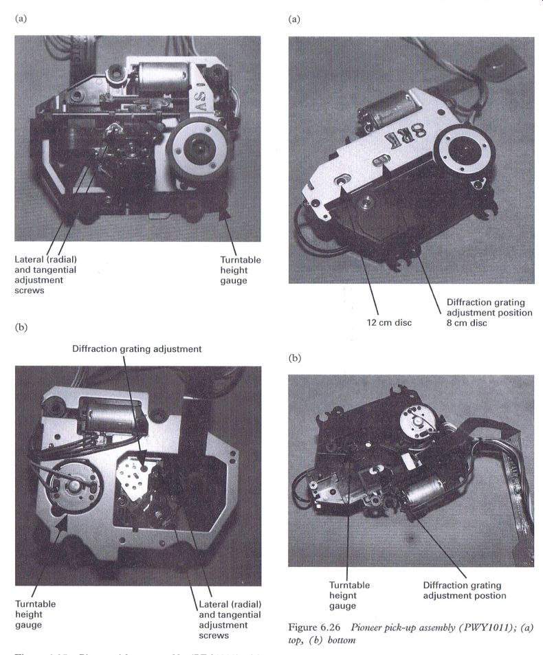
Figure 6.25 Pioneer pick-up assembly (PEA1030); (a) top, (b) bottom; Figsre 6.26 Pioneer pick-up assembly (PWY1011); (a)
top, (b) bottom
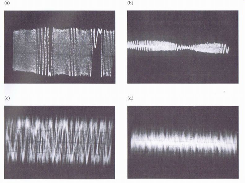
Figure 6.27 Tracking error waveform. (a) Maximum with a filter (as referred
to in relevant service manuals). Oscilloscope settings: at = 20 ms/cm,
y = 0.] V/cm (x is probe). (b) Minimum with a filter. Oscilloscope settings
as in (a). (c) Maximum without filter. Oscilloscope settings: x = 5 ms/cm,
y = 0.1 V/cm (x is probe). (d) Minimum without filter. Oscilloscope settings
as in (c)
Diffraction grating adjustment
Diffraction grating adjustment, based not only on the author's experience but on discussions with many engineers, can prove to be one of the most frustrating, as well as 'hit and miss', of all the adjustments previously described. Yet, providing a few basic ground rules are followed, there should be no major problems.
Fortunately not all players require adjustment of the diffraction grating as it may be factory set, as is now the case with the latest Pioneer optical block. This will no doubt produce a sigh of relief from the many engineers who endeavor to proceed with this adjustment with some trepidation.
Pioneer players in particular have, over the years, always required diffraction grating adjustment whenever an optical block has required replacement. The author's attempts at this adjustment following the relevant service manual have yet to prove successful, and the same applies to the majority of engineers. The main problem is related to obtaining the required minimum tracking error signal, which has always proved nigh impossible. A wide band oscilloscope is probably required in the region of 100~150 MHz, but these do not reside in many service workshops.
However, the following procedure, which is based upon Pioneer players using the PWYlOll and PEA1030 types of optical blocks, will prove successful in the majority of, if not all, cases of diffraction grating adjustment.
Before proceeding with this adjustment it is necessary to obtain the correct sized screwdriver:
a standard insulated 2.5 mm flat-bladed, parallel shaft screwdriver # no other will do.
Inserting the screwdriver into the adjustment point and turning the diffraction grating will indicate that there is a very small amount of rotation (no more than 20°) of the screwdriver, and care should be taken otherwise damage can be done to the grating adjustment which may prevent the correct adjustment point being achieved.
1. Set the player to the 'test mode' (refer to the Test Mode section)
Note. It is essential that the tangential and lateral (radial) adjustments have been provisionally set as previously described, otherwise there is the possibility of being unable to successfully complete the diffraction grating adjustment because the laser beam will be looking slightly 'sideways' at the tracks on the disc, preventing the tracking servo from locking onto the track correctly. Also it may well be necessary to check the laser power as described.
2. Connect the oscilloscope, via a 10:1 probe, to the tracking error (TR. ERR.) test point.
3. Move the optical block, by pressing the 'MAN SEARCH FWD'. or 'REV.' keys, until the grating point can be accessed.
Note. With the 'lens down' method of fitting the optical block, i.e. the single disc turntable platter and multi-disc players, the optical block is moved to approximately halfway across the playing area of the disc, at which point the grating adjustment can be accessed through a hole in the mounting plate. With the 'lens up" method, i.e. conventional single and twin disc players, the optical block is moved towards the outer edge of the disc where access can be gained to the grating adjustment. With these particular types of players it frequently proves useful to use an 8 cm disc with a playing time of 20 min, instead of a conventional 12 cm disc.
4. Press 'Track Forward' (TRK. FWD), or 'Program' (PGM). Disc 1 in the multi-disc players will be accepted. The laser and focus search sequences will now operate.
5. After 3 s, press 'PLAY'. The disc will now rotate at an acceptable speed.
6. Set the oscilloscope to observe the tracking error waveform (X = 5 ms, Y = 0.1 V cm^-1 with a 10:1 probe).
7 Insert the 2.5 mm screwdriver into the grating adjustment, and turn the screwdriver gently fully anticlockwise, taking care not to exert excessive pressure.
8 Now carefully turn the screwdriver fully clockwise, counting the number of maximum responses observed on the oscilloscope.
Note. If the response is a maximum when the screwdriver is turned fully anticlockwise, count this response as the first maximum.
9 Return the screwdriver to the fully anticlockwise position, and now turn the screwdriver to the mid-point maximum position.
Note. If an even number of maximum responses is observed (e.g. 8) then the mid-point could be either the fourth or fifth maximum response, but the fourth would be recommended at this point. If an odd number of maximum responses were observed (e.g. 9) then the fifth would be recommended at this point.
10 Ensure that the grating is adjusted to indicate an absolute maximum response.
11 Remove the screwdriver, press the 'PAUSE' control, and observe whether the player now plays the disc by monitoring the audio output, or checking that the front panel display is showing track and timing variations.
12 If this does not occur, press 'PAUSE' once more as the incorrect grating point has been selected.
If the incorrect grating point has been selected:
13 Re-adjust the grating to one of the maximums either side of the incorrect point, again ensuring that the absolute maximum response has been achieved.
Note. Referring to the examples mentioned in stage 9, with an even number of responses, take the next maximum response (e.g. fifth), and with an odd number of maximum responses, the one either side will suffice.
In effect, when carrying out this adjustment it can be observed that alternate maximums will enable the player to operate, whilst those in between will not. This is a consistent rule with all grating adjustments experienced by the author, and the reason for choosing the most central maximum that operates is to ensure that the mid tolerance point is selected.
The actual number of maximums that can be obtained can vary from one optical block to another, but a reasonable average is 9 or 10 for a new block. If the optical block has been abused with frequent unsuccessful adjustments, the actual grating adjustment point can wear and therefore the number of maximum responses can be much less.
This completes the recommended adjustment procedures, but occasions do arise when it may prove necessary to repeat or double check some of the adjustments to ensure that one adjustment has not inadvertently affected another.
------------------