Most domestic electronics products are control led by some form of system control, which whilst usually being extremely complex, provides virtually complete control of the operation and functioning of a specific item of electronic equipment.
Whilst the general aim of system control is no doubt to provide a wide range of facilities, the frequent problem that can occur is endeavoring to drive whatever the product may be, as well as achieve a complete understanding of what all the facilities a particular product may provide, and one can wonder if the extensive technology involved is really feasible when maybe only basic functions are required.
This is especially so where the extensive programming facilities that are possible enable a person to record a TV program which is scheduled to occur n days or weeks away, subject to world and political catastrophes, or even program a CD player capable of playing 6 to 12 discs in a specific order of disc and track selection.
The engineer comes into this when the requirement arises for servicing products which 'appear' to have problems in this area. Many engineers seem to have a love-hate relationship when the subject of system control arises; what does one look for when the system control 'apparently' goes on the blink? Many a tale has been told of the system controller chip being replaced, only to show that the previous one was probably operating satisfactorily after all, as the same symptoms still exist.
Thus this section endeavors to approach the subject in a fairly logical manner, in order that a reasonable appreciation may be achieved.
Generally the master system controller (Fig. 7.1) will control the overall functions of the player, and in practice the same concepts can be applied to other involved items such as VCRs, in-car products, etc. Communication between the controller and a controlled item is achieved by an interchange of information, and it is quite usual for an output expander to be included because the output circuit of the controller may not be sufficient to drive the controlled item, this may be more readily illustrated below.
Consider the operation of opening the drawer of the CD player, which will be similar to ejecting the tape from a VCR (Fig. 7.2). This aspect of system control is relatively straightforward, and operating the 'open' or 'eject' control causes data pulses from the system control via the relevant switch to pass back into the controller, which will pass a high or low level to the motor via the output expander. The 'open' or 'close' limit switches serve to indicate to the controller that either the drawer is closed, and therefore able to open, or that the drawer is open and the motor supply is removed.
This arrangement is similar to the optical block 'home' operation; when a CD player is first switched on, it is essential for the optical block to be at the start or 'home' position, and this is detected by the 'home' switch on the optical block.
The high level is usually a positive level to enable the motor to rotate in one direction, whilst the low level, usually a negative level, allows the reverse operation of the motor, and the zero is the 'off' or 'stop' condition.
Frequently a slave system controller is included which will communicate with the master system controller, especially where the control panel operates a unit remote from the main unit(s) of an overall system, and is typical of in-car and a wide range of hi-fi products.
Consider the focus search operation of a CD player when a disc is inserted into a player (Fig. 7.3). The system controller informs the CPU interface to commence the focus search sequence, which is a series of commands sent via the data lines, from the system control to the CPU interface, which then instructs the focus servo, also via data lines, to commence the focus search, whereby the lens is moved up and down a number of times.
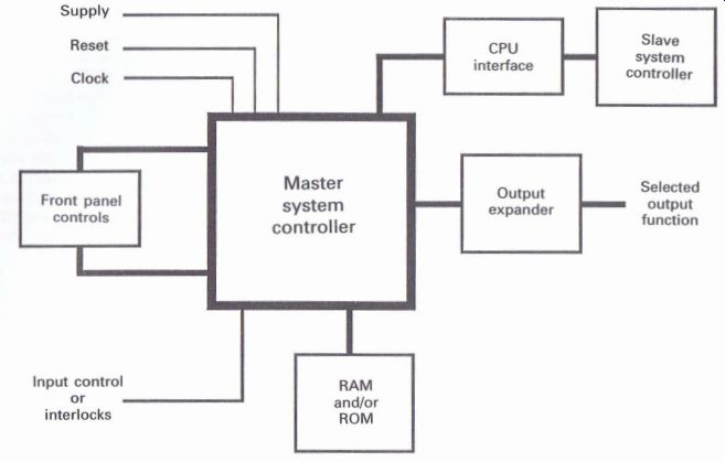
Figure 7.1 Basic system control arrangement
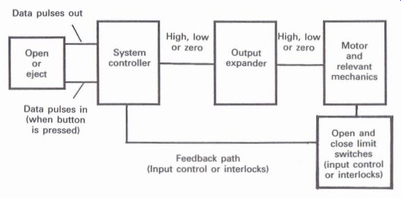
Figure 7.2 System control and motor drive arrangement
When focus has been achieved, the laser is assumed to be switched on; a high level will be obtained from the photo-diode array and RF amplifier, which is the focus OK (FOK) signal, which then informs the focus servo and the system control that focus has been achieved.
The system control then instructs the focus servo, via the CPU interface, to stop the search l function and close the focus servo loop to ensure that the laser maintains focus on the disc via the focus error signal.
Fig. 7.4 illustrates the system control arrangement that can be found in a wide range of players that utilize the CXD2500Q decoder, which, typical of many decoders, contains the CPU interface.
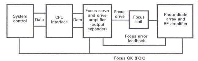
Figure 7.3 System control and focus servo arrangement
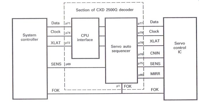
Figure 7.4 Basic system control and CPU interface
Whenever a function is required by the system controller in relation to a servo function, a data signal is sent to the CPU interface simultaneously with the clock signal. The data will comprise an address of 4 bits together with up to 16 further bits in relation to the command that has been requested, and the clock signal will be of the same time duration as the data signal. On completion of the data transfer, a latch signal (XLAT) will be sent to inform the CPU interface that the data transfer has been completed (Fig. 7.5).
These commands are transferred in a similar manner from the CPU interface to the servo auto sequencer, which can perform a series of functions without further commands from the system controller. Typical of this would be the series of operations that take place after selecting the 'play' command, which will include automatic focus and track jumping to achieve the correct playing of the disc.
The focus OK (FOK) signal will indicate with a high level that the laser has achieved focus on the disc, and is passed to the auto sequencer of the CPU interface and the system control. If the FOK signal does not go high, the system control will cease any further function of the auto sequencer and shut down.
The mirror signal continually ensures the laser is tracking on the track of the disc, whilst the table of contents (TOC) is being read, and whilst the disc is being played normally. When the TOC has been read it is necessary to move the optical block to the start of the music playing area of the disc by counting the required number of tracks ...
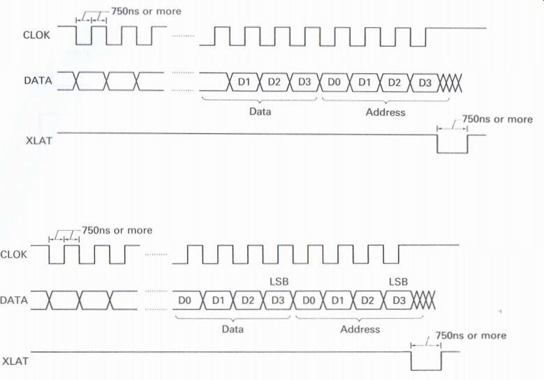
Figure 7.5 System control clock, data and latch signals
... (CNIN) to the start area to commence playing the disc.
The sense (SENS) signal will provide information on whether various stages of the selected function have been achieved and can be high or low depending upon the specific function that has been selected. Measurement of any of the clock, data and latch signals can prove difficult, but even if the required test equipment is available, the specific data information is rarely provided in the relevant service manuals. The preferred method of monitoring any of these signal lines is to ensure that there is some form of movement present on the oscilloscope, especially when some of the front panel controls are selected.
The circuit shown in Fig. 7.6 is an extract from a typical CD player, showing the system controller, keyboard and display.
The three important items described in the fault diagnosis as the 'magic three' are:
p30/31 clock
Communication outputs to the CPU interface are:
p6 CLOK (clock)
p7 DATA
p19 XLAT (latch)
The 'laser on' (LDON) signal is output from p29, with p28 registering the focus OK (FOK) signal.
Opening and closing the disc drawer
When the drawer is selected to 'open', p24 (LOUT) will go high and drive the motor to open the drawer and release the disc. When the drawer is fully open p25 (open) will go low, which in turn will cause p24 to go to zero and stop the motor.
Closing the drawer is achieved when p23 (LIN) goes high to drive the motor to close the drawer and clamp the disc. When this is achieved, p26 (CLMP) will go zero to enable the motor to stop.
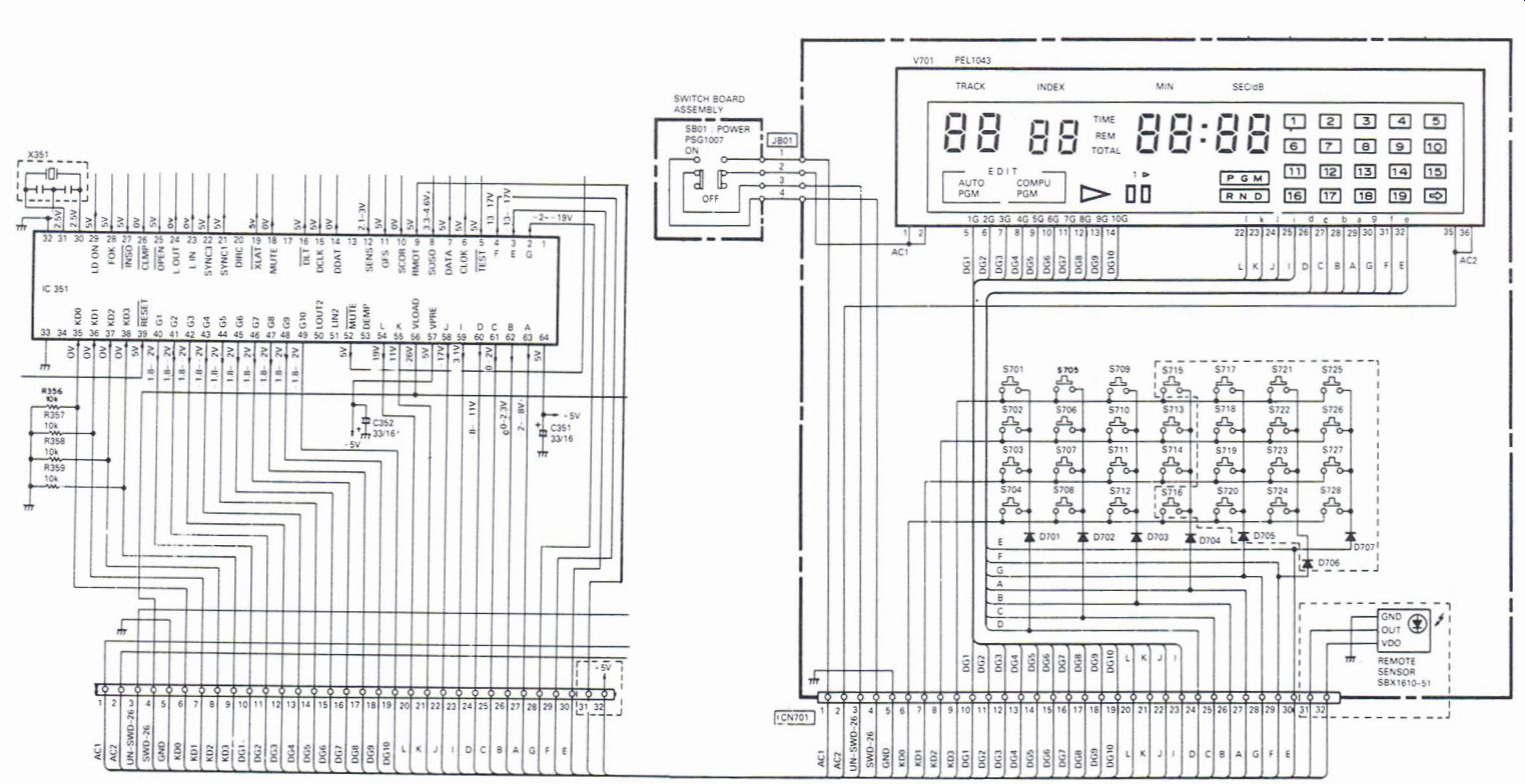
Figure 7.6 Example of a system control circuit in a CD player
Sensing whether the optical block is in the home position In order that the system controller knows that the optical block is at the start, home, or inside position, to enable the TOC to be read either at switch on, or when a disc is inserted, the optical block is driven by the carriage motor until the inside switch closes and p27 goes low, stopping the carriage motor via data interchange.
Front panel controls and display The various segments on the display are controlled from pins 40 to 49 (GO-G10), and the A~L lines from pins 1, 2, 3, 54, 55 and 58-63. The A-G lines are also fed to the keyboard matrix through the relevant diodes (D701~D707), with each key making contact with a horizontal line of the matrix to connect to the KDO-KD3 lines, which go to pins 35-38.
Data pulses will appear on the AiG lines, and will appear on one of the KDO-KD3 lines depending upon which key is selected.
Some system control arrangements only provide pulses on the equivalent A-G lines when a relevant key is selected, and therefore in fault diagnosis it is important to ensure that no pulses appear on the KDO-KD3 lines when no keys are depressed.
It is quite often known for keys to be jammed, which effectively 'locks up' the system control, so checking the KDO-KD3 lines can be extremely useful.
Remote control signals are received by the remote sensor and applied to pin 31 (RMDT).
Occasionally some form of memory is included with the system control, in the form of either ROM or RAM, which is used to ensure that the player, or even VCR or other product, carries out specific functions. In the case of programmable players it is necessary to store a sequence or program of tracks on the disc, or discs in the case of multi-disc players, to be played in some specific order.
The information outlined above should enable engineers to achieve a reasonable appreciation of typical system control arrangements.
------------------