Generally speaking, with the exception of supply voltages, physical size and compactness of in-car CD players, the basic technology is the same as that for the hi-fi range of players. This section will therefore be relatively brief with the main intention of considering certain important areas that will hopefully assist engineers who have to service these products.
These players usually appear either as single disc players, which are fitted into the dashboard area of the vehicle, or as multi-disc players which are fitted into the boot of the car (Fig. 8.1).
Single disc players
Single disc players can appear either as an additional unit connected to an existing system which in itself is capable of driving the CD player, or as a virtual stand-alone unit which may also have a tuner and amplifier facility included.
Single disc players in particular can obviously be extremely compact units, and it is important to ensure that the relevant service manual is available in order to determine the correct dismantling, re-assembly and possible adjustment procedures.
The CD is inserted and ejected usually by some form of motor-driven mechanism, and the playing procedure is usually relatively simple in order to minimize distraction to the driver, especially as he/she may be proceeding down the outside lane of a motorway at 70 mph.
Multi-disc players
There are a wide range of multi-disc players that are fitted into the boots of cars, though they have also been known to be fitted under one of the seats; and they are operated by the head unit fitted into the dashboard. A magazine is used in these players, which can accommodate from 6 to 12 discs, enabling an extensive selection of music to be available and providing a total playing time of 5-12 h, depending upon the system installed and the type of discs being played.
With these players two types are generally available with respect to the initial operation when a magazine is first inserted into the unit.
1. No initialization process takes place when the magazine is first inserted, and the player commences playing discs when requested by the operator.
2. An initialization process commences the moment the magazine is inserted, where each tray of the magazine is checked to determine which tray contains a disc inserted, and this information is stored in an internal memory; this process is typical of Pioneer players.
Depending upon the type of multi-disc player, either the magazine or the optical assembly is moved vertically to the correct position to enable a specific disc to be selected, clamped into position, and played.
Concerning the installation of these players it is essential that the procedure recommended in either the users' manual or the service manual are accurately followed. Some players can be vertically or horizontally mounted, and with these it is possible that some internal support springs will have to be adjusted to compensate for the weight of the player mechanism. If this is not correct internal damage can result, or excessive skipping, jumping and even total inability to play can result. However, the majority of these players are fitted horizontally, though the author has been aware of players being fitted on their side, or even upside down in the roof of the boot area of the vehicle, which has resulted in some delightful dismantling techniques in order to restore the unit back to the original playing ability. Possibly the ...
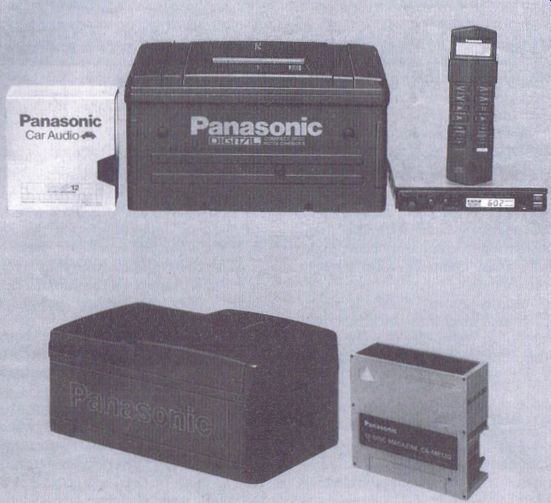
Figure 8.1 In-car CD players
... 'best' incorrect installation observed was into an extremely expensive brand new car, where the owner required the multi-disc unit to be fitted on its side, at a fairly acute angle adjacent to the driver's left leg in the driving area of the car next to the gear change, so that the magazine could also be conveniently changed as required. This installation required extensive cutting of carpeting to enable the mounting to be achieved--and all was well until the first disc was selected!! With the various types of multi-disc players available, a wide range of magazines are avail able, a selection of which are shown in Figs 8.2 - 8.5.
Some magazines have trays which can be drawn open. It is essential to be aware that some magazines contain trays that can only be withdrawn singly, and opening more than one tray at a time when inserting a disc can cause damage to the ...
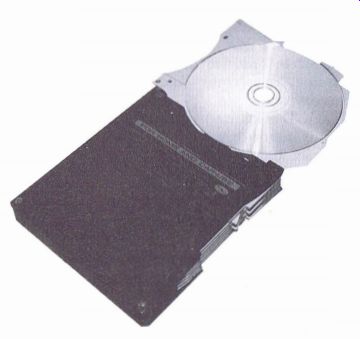
Figure 8.2 Example of magazine with disc inserted (Pioneer)
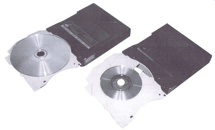
Figure 8.3 Examples of 12 cm and 8 cm disc magazines (Pioneer)
... tray, which can result in jamming of the player mechanism if more than one tray is inadvertently withdrawn from the player.
With other magazines it is possible to completely remove all the trays when inserting the disc, but as always enough emphasis cannot be placed upon the need to refer to the relevant instructions for the magazines and players concerned.
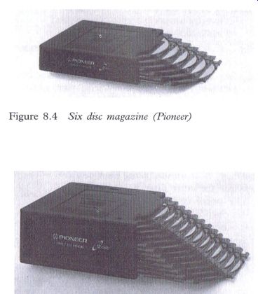
Figure 8.4 Six disc magazine (Pioneer); Figure 8.5 Twelve disc magazine (Pioneer)
Multi-disc player mechanism control
When the magazine is inserted into these players, there is usually some switching that can determine the position of either the magazine or the optical assembly, and whether a disc is clamped ready to play or a tray is in or out of the magazine. Also some form of switching Will determine that a magazine has been inserted, or that the ejection process has been completed. All the switching information is usually sent to the system control-
--------------
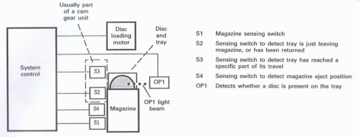
Figure 8.6 Method of detecting that there is a disc on the tray
S1 Magazine sensing switch
S2 Sensing switch to detect tray is just leaving magazine, or has been returned
S3 Sensing switch to detect tray has reached a specific part of its travel
S4 Sensing switch to detect magazine eject position
OP1 Detects whether a disc is present on the tray
S5 Sensing switch to detect upper elevation position
------------------

Figure 8.7 Detecting the elevation position of the magazine or optical
block
If the player is of the type that initializes when a magazine is inserted, a fairly complex routine is automatically followed, which involves sensing switches and opto couplers to determine whether a disc is present on the tray (Fig. 8.6) and also the vertical position of the magazine or optical block (Fig. 8.7).
When the magazine is first inserted, and the initialization process commences on the relevant players, S1 detects that the magazine is inserted and informs the system controller, which usually switches on any applicable power supply.
The disc loading motor now commences to remove the tray from the magazine, and as this is started, S2 detects that the tray is just about to leave the magazine, and may be referred to as the tray position (TRPN) switch. S3 detects when the tray has reached a certain position, and instructs the system control to monitor via the opto coupler, OP1, whether a disc is present on the tray. The tray continues to move slightly further, when S3 changes its state, at which point the loading motor reverses, to return the tray back into the magazine. S3 may be referred to as the 'disc present' (DCPN) switch.
When the tray is back into the magazine, S2 will change its state, and the magazine or optical assembly now moves to the next position in readiness for the next disc.
The pulse generator is usually either a switch or an opto coupler, depending upon the method that is being utilized. As the elevation motor raises or lowers the magazine or optical block, a series of pulses will be generated which will enable the system controller to determine that the next disc, or selected disc in the normal play mode, has been reached. An upper limit switch, S4, may be included in some models to detect that the upper level of elevation has been reached.

Figure 8.8 Pioneer CDX-M30 power supply block diagram
When the magazine is ejected, the elevation motor will restore the magazine or the optical block back to the start position when the magazine was first inserted. Then the loading motor will follow a sequence to release any retaining mechanism to enable the magazine to eject. When this position has been achieved, S5 will change its state and cause the disc loading motor to reverse until S5 changes its state once more when the loading motor will stop to await the next magazine.
The above information will provide an appreciation of this type of mechanism control, but a word of warning to the unwary: the first of the Pioneer multi-disc players, CDX-M100, had a method of reversing the tray back into the magazine immediately a disc was detected during the initialization process, but if there was no disc present then the tray would continue to be extracted until a limit switch detected that this position had been reached. Therefore the process took slightly longer if there was no disc present on a tray compared to when one was present, and it has been known for engineers to dismantle the mechanism on the quite reasonable belief that the mechanism may be jamming up when a disc is present as the tray travel was not as far. All the later models take exactly the same amount of time whether a disc is present or not.
Power supplies
The power supplies of in-car CD players tend to have a complexity of their own, usually for two reasons: they are frequently distributed throughout the circuit and require a certain amount of time to trace the relevant sources and subsequent paths; also, there is usually a d.c.-d.c. converter, and this comes either in the form of an IC to provide either another voltage level, or more specifically a negative potential to enable servo circuits to perform their work adequately.

Figure 8.9 Extract of power supply circuit of the Panasonic CX-DP10EN
Figs 8.8 and 8.9 are two power supply diagrams, in block or circuit form, which provide an overview of the methods that exist. Essentially the main section of any power supply is controlled by the system controller, though there naturally has to be some form of + 5 V supply to maintain a supply to the controller when the in-car unit is switched off.
The battery (BATT) supply is applied to three blocks:
1. Reg 5: to supply a continual + 5 V to maintain the Vcc voltage for the system controller.
2. VD: to supply 9.5 V to drive motors and provide other 5 V supplies.
3. 8 V: to supply audio pre-amplifier and audio isolator or buffer circuits.
When a magazine is inserted the LOAD output from pin 65 of the system controller will switch on the VD and Q802 circuits, to enable the initialization process to take place. When 'play' is selected, pin 41 (POWER) and pin 65 (LOAD) will switch on the VD circuit together with Q802 to provide motor supplies, and also Q652 to provide two + 5 V supplies via Q 631 and IC661, as well as the + 8 V which is the Vcc supply to a driver IC which operates the focus and tracking coils, and the carriage and spindle motors.
With this circuit there is no negative supply, which is usually required in CD players to enable the focus and tracking coils to move either side of a neutral position, but in the later Pioneer in-car CD players a reference voltage (V Ref.) is derived to provide a + 2.5 V supply which is used as the neutral position potential, with + 5 V, which is in effect + 2.5 V compared to the V. Ref., and ground or 0 V, which is in effect -2.5 V compared to the V. Ref, and it is important to be aware of this fact when adjusting these CD players (see below).
The section of circuit shown in Fig. 8.9 is interesting insomuch that a--5 V potential is derived from IC701. The power supply is applied) via the fuse at the bottom right-hand corner of the diagram to be fed to Q704 via LC701, which provides a low current + 5 V to the system controller, whilst the player is in the 'off' condition.
The system controller provides the power switch on signal via pin 1 of the connector CN40, which controls Q703, Q705 and IC701 and their associated circuits. The + 14.4 V appears when the accessory switch on the ignition is switched on providing ACC via pin 12 of CN40, and is applied to pins 1 of IC701 and IC702, the emitter of Q701, the collector of Q703, and the base of Q702, which will conduct. Q703 collector will go low when switched on, which in turn will now cause Q702 to switch off, with pin 3 of IC702 going high, which via pin 1 will now cause Q701 to conduct as pin 1 goes sufficiently low. The voltage at Q701 emitter provides + 10 V to pin 1 of IC703 and pin 12 of CN40, with IC703 providing + 5 V for a range of applications via pins 7, 8 and 9 of CN40.
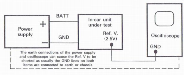
Figure 8.10 Precautions to observe when adjusting some of the Pioneers
in-car CD players When Q705 is switched, this causes Q706 to conduct as
a result of the + 5 V from pin 3 of IC703, and the output from Q706 is
in effect a back up + 5 V to provide an increased current handling capability
for the system controller.
As previously mentioned, when IC701 (which is a d.c.-d.c. converter) switches on, 5 V will be provided at pin 2 to be applied to a range of circuits via pins 2, 3 and 4 of CN40.
Outline of adjustments
When carrying out adjustments of the in-car CD players, many are quite similar to those outlined in Section 6, but it is important to refer to the relevant service manuals wherever possible as requirements vary from one manufacturer to another, with possibly the Pioneer in-car players being the most involved; it is with respect to these players that care must be taken when connecting the oscilloscope, as outlined in Fig. 8.10.
Because the Ref. V of 2.5 V is used as the neutral position reference within the player for the operation of the servos, the ground connection of the oscilloscope is required to be connected to this point when carrying out specific adjustments. As it is relatively common practice with some manufacturers of low voltage power supplies to connect the negative potential of the low voltage power supply directly to the chassis or ground of the unit. If the oscilloscope chassis is connected to the earth connection of the mains plug, and likewise for the ground or chassis of the power supply, a situation can be created that when all the connections are made with respect to relevant adjustments, for the + 2.5 V Ref. V to be effectively shorted to ground via the earth loop, with the possibility of dire consequences.
To minimize this occurring with some types of power supplies, the relevant service manual suggests that the frame of the measuring instrument (oscilloscope) be changed to a ?floating status. Whilst some engineers may feel concerned with this procedure, it should be remembered that many oscilloscopes operate in this condition for working on television products, and providing the workshop environment uses isolation transformers and also residual current circuit breakers (RCCB), engineers should feel confident with this procedure; but of course it is recommended that the insulation of the oscilloscope is checked at regular intervals, as recommended in Appendix 2.
Test mode
As a test mode is provided with most Pioneer players (an example of which is shown in Fig. 8.2 where specific keys provide a range of different functions), and as this can vary from one player system to another, complete details are always available in the service manual, but in line with the test mode facilities previously outlined in the sections related to Adjustments and Fault Diagnosis, the test mode can prove extremely useful to the engineers servicing these particular products.

Figure 8.11 Typical test mode low char t for Pioneer in-car CD players.
Fault diagnosis
The most common problems that tend to occur are usually related to either power supply problems, or those related to skipping and jumping, especially as the in-car CD player is required to operate in an extremely unfriendly environment.
Not only is the player required to operate on demand in varying temperature conditions from Typical test mode flow chart for Pioneer in-car CD players the coldest to the hottest (though many players do have a temperature sensing circuit, which switches the player off when extremely high temperatures are encountered), but it is also expected to function no matter what the condition of road surface and thus the player is not expected to give the slightest hint of a skip or jump even when travelling at speed over the bumpiest of surfaces. The installation, mentioned, is important, but cars vary in their suspension characteristics, and therefore it is not unreasonable to expect some form of strain on the system, despite the extremely effective internal suspension techniques employed in many players. If skipping and jumping does occur, the relevant areas referred to in Section 9 should be considered, with additional consideration being given to the actual installation and suspension of the vehicle concerned.
------------------