With CD players, many faults can be attributed to the mechanical aspects, and actual electronic faults are generally not so common.
The author has never recommended a standard list of CD player faults, on the basis that if the relevant recommendations are implemented with respect to a specific type of player, and if the 'cure' is not achieved, where does one go from here!? If the optical block or the spindle motor is replaced, because these items are frequently suspected, and the original fault is still present, a waste of time has occurred with respect to the engineer involved, and the eventual bill for the customer may well be unnecessarily high.
Another area where problems can occur is in situations where nothing appears to be happening with the player and the system controller becomes the major suspect, especially as it controls the overall operation of the player. Nothing can be more annoying than replacing a 60 pin (or more) dual in line or four-sided flat pack, only to prove that the component that has been replaced was not defective after all, as the same fault condition still persists.
The test or service mode facilities that are available with some players can greatly assist in fault diagnosis, and reference to these will be included as applicable, though reference to the relevant service manual will provide more specific information for a particular model.
Therefore, with respect to fault diagnosis, a recommended checking sequence is preferred. Whilst it can prove difficult to be absolutely definitive when recommending specific procedures, experience will enable some short cuts to be taken; the following procedures and information have been based on previous encounters with players of various types.
Before really delving into recommended procedures or methods, it is useful at this stage to consider the basic 'start up' routine that most CD players adopt at 'switch on' and when a disc is inserted (Fig. 9.1). Though some players may vary slightly from this routine, it is a useful basis from which to consider whether a player is at least trying to make some attempt to conform to the requirements of playing a disc.
Being aware of the basic initialization routine of a typical CD player, together with some preliminary observations, can prove extremely useful in helping to determine some initial symptoms with respect to fault diagnosis. If problems are encountered, then the following fault diagnosis procedures will generally assist in determining the faulty area of most CD players.
Suggested check list to assist in determining the possible faulty area, in relation to a specific symptom The check list given in Fig. 9.2 is not intended to be exhaustive, i.e. the last word in CD player fault diagnosis, but it should at least guide engineers towards resolving most problems, and the following recommended stages (Fig. 9.3) are represented in a logical manner, so that, if 'push comes to shove', following each of the stages and applying some of the relevant suggestions should assist.
Two of the main problems with servicing CD players are inheriting someone else's frustrated attempts, and those nasty obscure faults that all attempts to resolve bear little relevance to the
final diagnosis, and which frequently combine together to create what can occasionally become a 'horrendous' experience.
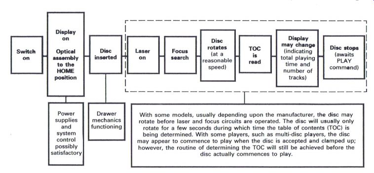
Figure 9.1 Typical CD player initial operating sequence
-----------------
Power supplies and system control possibly satisfactory
Drawer mechanics functioning
With some models, usually depending upon the manufacturer , the disc may rot at e before laser and focus circuit s are operated. The disc will usually only rot at e for a few seconds during which time the table of contents (TOC) is being determined. With some players, such as multi-disc players, the disc may appear to commence to play when the disc is accepted and clamped up; however , the routine of determining the TOC will still be achieved before the disc actually commences to play.
-----------------
A recent example occurred with a respected engineer who had inherited a Pioneer three-magazine player to service, which totally refused to respond in any manner or form, and certainly gave the final impression of a system control problem. Fortunately previous incumbents of the unit had decided that the unit required a more expert approach, and nothing drastic had taken place.
So the engineer reluctantly chose to replace the system controller; as in many cases of this nature, this proved that this item was working quite satisfactorily, as no further progress had been made.
It was now a case of back to basics, and a thorough check of all things mechanical was necessary, with the final result being that a small piece of plastic 'swarf' had jammed itself within a couple of the magazine selection gears thereby preventing any further progress or operation.
Many engineers will have experienced the somewhat frustrating problems that can create such catastrophic symptoms, and whilst not endeavoring to bolt the stable door after the horse has bolted, an overall logical approach to fault diagnosis should assist either the uninitiated, or those who may find themselves floundering in the 'slough of despair'.
Stage 1: initial checks Before proceeding with any major diagnostic thoughts or procedures it is always useful to look round the inside of the player to observe if any strange happenings have occurred, or are taking place (Fig. 9.4).
Has someone been here before? Unfortunately CD players do tend to be a 'tweakers' paradise', and of course all presets come fitted with a screwdriver slot which is meant for turning ... so why not turn it? Are the preset controls at or around the midpoint settings? If they are at one extreme then the possibility exists that the dreaded twiddler has cast a magic spell, especially with focus and tracking gain controls, as not a lot will happen if they are at the minimum setting.
Many engineers frequently have a 'tweak', but of course the golden rule is to return the preset back to the original position if nothing specific occurs. If this is not done, any fault condition can be further compounded by unnecessary 'adjustment' of the preset controls.
Are all wiring looms still nice and tidy? If they are somewhat disheveled it is a sure sign that items have been removed and replaced.
It is frequently a pity that engineers are not fitted with X-ray vision in order that the underside of the PCB can be viewed more easily without removal. Some methods and techniques of removing and replacing 80 pin four-sided flat packs can indeed cause trauma of the most undesirable kind, to engineer and customer alike, especially by way of the final bill.
----------------------
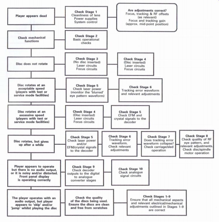
Figure 9.2 CD player fault symptom check list
Player w a dead Check mechanical functions Disc does not rotate Disc rotates at an (player; with test or service mode facilities) Disc rotates at an excessive speed (players with test or service mode facilities) Disc rotates, but gives up after a while Player appears to operate but there is no audio output, Front panel display is operating correctly or it is noisy and/or distorted.
The player operates with an audio output, but player appears to 'skip' and/or 'jump' whilst playing the disc
----------
Check Stage 1 Cleanliness of lens Power supplies System control
Check Stage 2 Basic operational checks
Check Stage 3 (No disc inserted) Laser circuits Focus circuits
Check Stage 5 Check laser power (monitor the 'blurred' eye pattern waveform)
Check Stage 4 (Disc inserted) Laser circuits Focus circuits
Check Stage
Check laser power and/or
_ EFM/crystal signals to the decoder
_ outputs to the digital
Check Stage 9
Check decoder to analog converter stages
Check the quality of the discs being used.
and free from scratches
Ensure the discs are clear
----------------
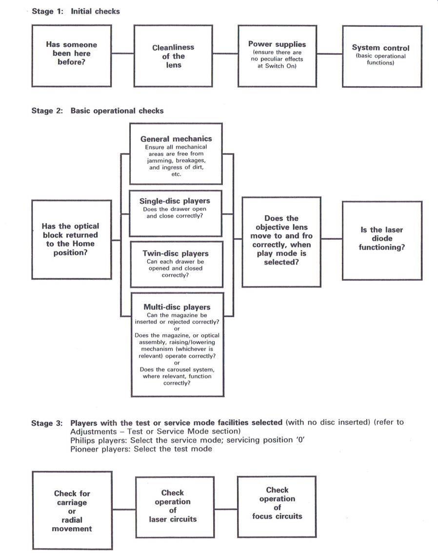
Figure 9.3 Suggested stages in fault diagnosis--Stages 1-3
Stage 1: Initial checks A list of stages which if applied in a logical sequence as relevant to individual players will assist engineers in determining where, in a CD player, a specific fault may be occurring. Each stage is subsequently expanded to provide further guidance where possible.
A list of stages which if applied in a logical sequence as relevant to individual players will assist engineers in determining where, in a CD player , a specific fault may be occurring. Each stage is subsequently expanded to provide fur t her guidance where possible.
-----------------
Stage 2: Basic operational checks
General mechanics Ensure all mechanical areas are free from jamming, breakages, and ingress of dirt, etc.
Has the optical block returned to the Home position? Single-disc players Does the drawer open and close correctly? Twin-disc players Can each drawer be opened and closed correctly? Does the objective lens move to and fro correctly, when play mode is selected? Is the laser diode functioning?
Multi-disc players
Can the magazine be inserted or rejected correctly? or Does the magazine, or optical assembly, raising/lowering mechanism (whichever is relevant) operate correctly? or Does the carousel system, where relevant, function correctly?
Stage 2: Basic operational checks
----------
Figure 9.3 Suggested stages in fault diagnosis--Stages 1-3
Stage 3: Players with the test or service mode facilities selected (with no disc inserted) (refer to Adjustments--Test or Service Mode section) Philips players: Select the service mode; servicing position '0' Pioneer players: Select the test mode
Check for carriage or radial movement
Check operation of laser circuits
Check operation of focus circuits
---------
Stage 4:
Players with the test or service mode facilities selected (with a disc inserted) (refer to Adjustments--Test or Service Mode section) Philips players: Operate the NEXT key; Servicing position '1' Pioneer players: Operate track forward (TRK FWD) or Program (PGM)
Stage 5: Players with the test or service mode facilities selected (with a disc inserted) (refer to Adjustments--Test or Service Mode section)
Philips players: Operate NEXT again, Servicing position '2' Pioneer players: Operate PLAY
Note: Always wait 3 s after operating the relevant functions outlined in Stage 4 before operating any of the above keys, otherwise disc 'runaway' is guaranteed
Stage 6: Players with the test or service mode facilities selected as in Stage 5 This stage can apply particularly to Pioneer players or any players that require adjustment of the diffraction grating. The disc will be at speed
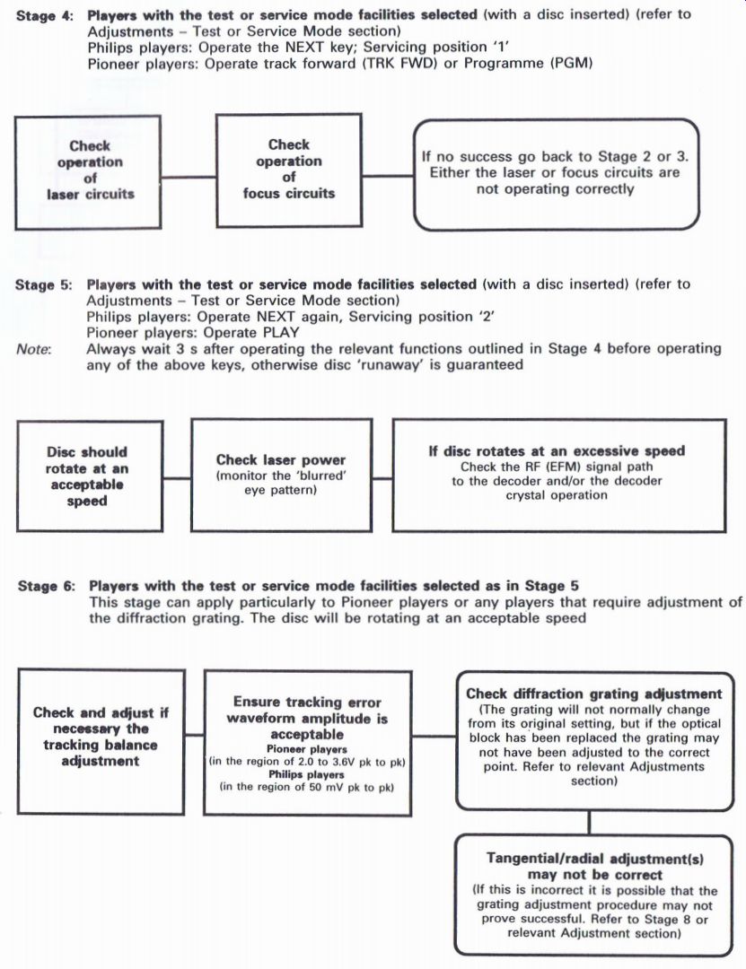
Figure 9.3 (Continued) Suggested stages in fault diagnosis--Stages 46
------
Stage 7: Players with the test or service mode facilities selected as in Stage 5 This stage can apply particularly to those players that have the facility of 'opening' and 'closing' the tracking servo
----------------------
Figure 9.3 (Continued) Suggested stages in fault diagnosis--Stages 4-6
Stage 8: Players without the test or service mode facility and/or Players with the test or service mode facilities selected as in Stage 5
This stage can apply particularly to those players that have the facility of 'opening' and 'closing' the tracking servo
Stage 9: Player operating in the normal Play mode 1
Stage 10: Player operating in the normal play mode 2
----------------
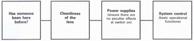
Figure 9.4 Initial checks
On some players, such as Pioneer, it is possible to determine whether the spindle motor has been changed, because the disc table spacer may be missing from the original location on the optical assembly.
Cleanliness of the lens It is essential to ensure that the lens is absolutely clean, as many a player has fallen by the wayside as the result of a dirty lens.
Many of the hi-fi players, which just have a drawer or magazine for inserting the disc, are very good at minimizing the ingress of dirt into the player, but many of the portable 'mean machine' and 'ghetto blaster' types, which have a lift-up lid to insert the disc, prove extremely good at allowing dirt to find its way onto the lens of the optical block.
Also some of the hi-fi midi systems have ventilation slots in the cover or back of the complete unit. So, by virtue of the natural ventilation of the system, it is possible for dirt and dust to find its way into the unit, and this naturally always seems to accumulate on the lens of the optical block.
In fact there may be a good reason as to why this usually happens; it may be due to the fact that the lens on the optical block is usually composed of a plastic material, and sitting just above the lens will be a CD rotating at anything from 500 to 200 rpm, or thereabouts. What better combination is required for a static generator, where the lens can attract dirt, dust, smoke or pollution from the surrounding environment to deposit itself upon the surface of the lens, thereby effectively inhibiting the laser beam from doing its necessary job of extracting the information from the disc.
Cleaning the lens should be carried out with care, and because some lenses have a special coating on them, chemical-based cleaning agents are not generally recommended. The author's tried and tested method is to gently rotate a 'moistened' cotton bud over the surface of the lens, and gently polish up the lens with a dry cotton bud if necessary.
There are some special lens-cleaning discs available which are inserted into the player. The actual process of inserting these special discs is intended to clean the lens, a process which sounds somewhat traumatic as far as the lens is concerned, and this is a method which is not generally recommended, though engineers through their own experience will be aware of the virtues of this method of cleaning the lens.
Power supplies
Ensure there are no peculiar effects at switch on.
The majority of CD players, especially of the hi-fi type, incorporate a balanced power supply which provides positive and negative supplies to drive the electro-mechanical items such as focus and tracking coils, and relevant motors, as well as other areas of the circuits. It can prove useful to ensure the supplies and circuit protectors where fitted are all correct and operational, especially if there are problems when first switching on, and motors are observed to be either running or buzzing because they may be stalled due to some mechanical aspect being at one end of its travel.
Even observing the focus lens can prove interesting, as usually it will be in a neutral position, especially with no disc inserted. If it is either sucked right in to the optical block or trying to climb out of its bed this is usually sufficient to indicate that all may not be well with the power supply and related drive circuits.
With the majority of CD players, the positive and negative 8/16 V supplies are used to drive the electro-mechanical components, such as focus and tracking coils and any associated motors, with their
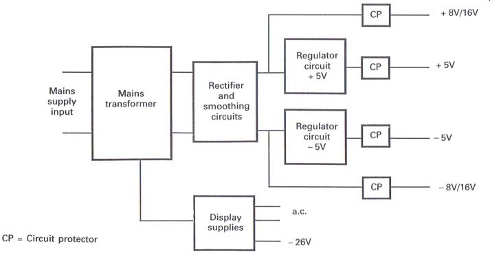
Figure 9.5 Typical power supply block diagram
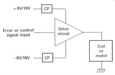
Figure 9.6 Typical servo drive circuit relevant direction of movement
being related to the applied polarity derived via the necessary drive circuits
(Fig. 9.6).
When the coils are in their neutral position, or the motors are stopped, this is achieved by applying a neutral or zero signal to the drive circuit, which in turn will provide a zero output to effectively switch off the supply to the relevant device.
The principle of operation of the circuit shown in Fig. 9.6 is that with a zero input, a zero output will be achieved, and therefore the coil or motor will not operate. If the input is positive or negative, the resultant output will cause the coil or motor to Operate in one direction or the other, depending upon the polarity of the input.
Circuit protectors are frequently included in many of the supply lines, though not necessarily all of them. Should one of the circuit protectors become defective, causing one of the supplies to be missing, the result will be an in balance in the operation of the drive circuit, which in turn will cause a voltage to appear at the output which will cause the coil or motor to function.
System control--basic operational functions
Amongst the wide range of sophisticated domestic electronic products that service engineers are called upon to service in these modern times, there is usually lurking somewhere within the inner depths a multi-pin pack package, either dual in line or four-sided flat pack, that goes under the identification of the microprocessor or system controller.
Service engineers 'love' them, as these mysterious and sometimes magical 'black boxes' appear to assume virtual total control of whatever the product may be, and unfortunately, by the nature of their complexity, they are blamed for a multitude of sins of which they are usually quite innocent.
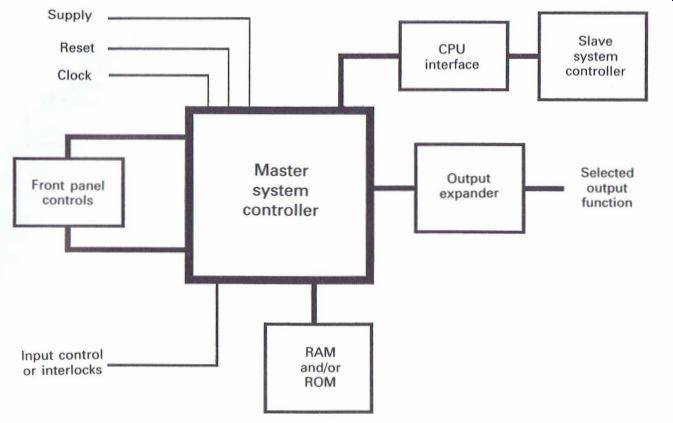
Figure 9.7 Basic system control arrangement
As a result, these items are frequently replaced, and because they are usually found as the dual in line or four-sided flat pack type, and are therefore an absolute 'delight' to change, there can be nothing more frustrating than having replaced one of these 'beasts' only to find that the existing fault is still apparent, or even worse, extra symptoms have occurred as a result of some dubious soldering, broken print or other unspeakable niceties that can occur.
Experience has shown all too frequently that it is usually some straightforward and rather mundane aspect of the circuit that has been the real cause of the fault condition, thereby preventing the system controller from performing the function that has been selected.
Whilst Section 7 covers the system control aspect, it is worthwhile repeating certain diagrams as necessary in order to maintain consistency when considering to which area of the CD player the fault symptom relates, especially the basic outline of the concept of the system control as shown in Fig. 9.7.
When considering a recommended procedure in order to determine whether the system controller may or may not be at fault, it is essential as a preliminary process of elimination to check the 'magic tree':
1. Supplies to the 'beast' (to make it work).
Usually the supply to the system controller is + 5 V, occasions have been known when this supply has been as low as only + 4.5 V or + 4 V and the system control has refused point blank to function, and therefore it can prove useful to Check that this supply is correct.
2. Reset (to make it work correctly). As previously mentioned, the reset is necessary to ensure that the system controller is in the correct logic state at switch on, to ensure the various internal sequences and functions are in their required state(s) to enable correct operation to be achieved.
If the reset function is incorrect, some players can give the impression of being totally 'dead', with no display indications, possibly pointing to a power supply problem, and it certainly can prove worthwhile to ensure all supplies are correct.
It is also possible for random display functions to appear, with the possibility of some totally illogical functions taking place, though some other system control malfunctions can create functioning problems which will be discussed later.
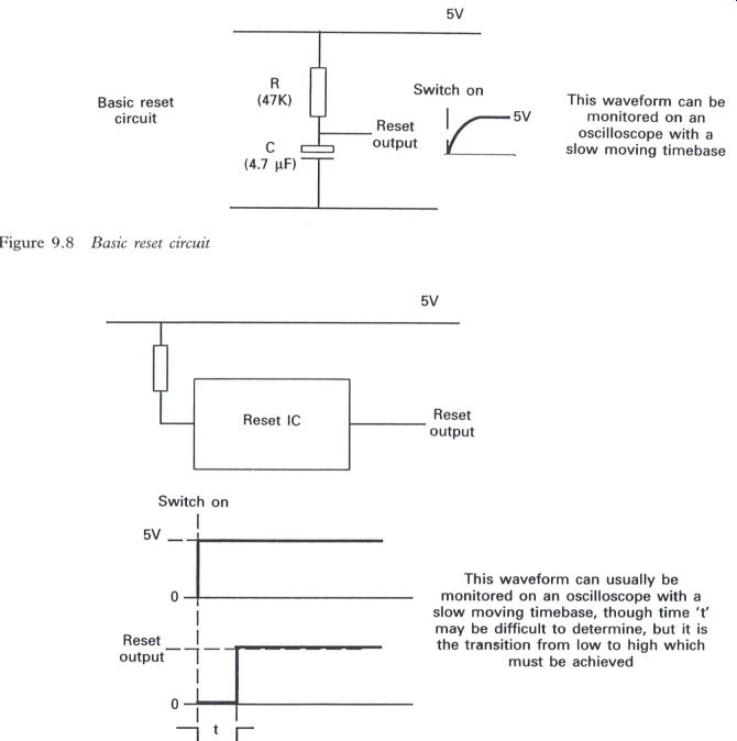
Figure 9.8 Basic reset circuit---This waveform can be monitored on an oscilloscope
with a slow moving timebase
Figure 9.9 Alternative reset circuit---This waveform can usually be monitored on an oscilloscope with a slow moving timebase, though time 't' may be difficult to determine, but it is the transition from low to high which must be achieved.
It may be necessary to refer to the relevant service manual in order to determine the correct reset output requirements, but the information given in Fig. 9.8 may prove useful. Basically the reset pulse should complete its required function a brief period of time after switching on the player or associated equipment. The component values shown in Fig. 9.8 are an example from a particular player, and may vary from one player or manufacturer to another.
The information given in Fig. 9.9 should help engineers in determining whether the reset circuit is functioning correctly, but it is also useful to appreciate that some system control circuits are known not to provide a clock signal if the reset circuit is not operating correctly.
3. Clock (to help it along or perform the necessary functions). This is usually derived from a crystal oscillator within the system control IC, and will operate at a frequency ranging from 4 MHz to greater than 8 MHZ, depending upon manufacturer and type of player.
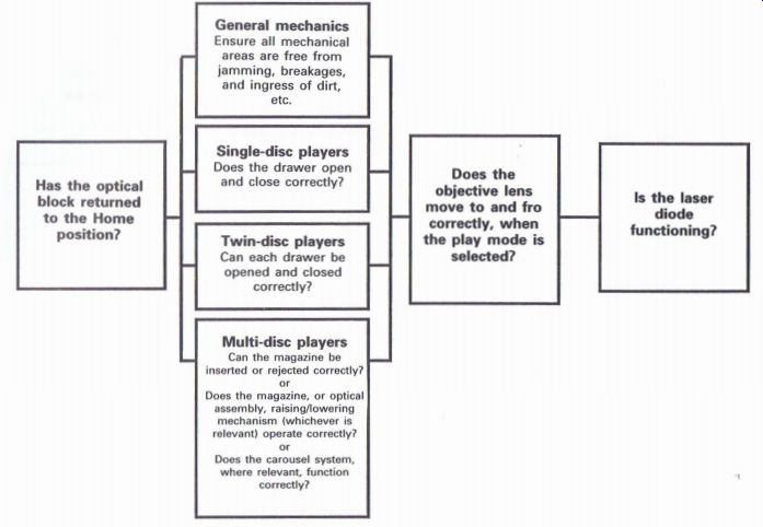
Figure 9.10 Stage 2: basic operational checks
----------------------------
General mechanics
Ensure all mechanical areas are free from jamming, breakages, and ingress of dirt, etc.
Single-disc players
_ Does the drawer open Has the optical and close correctly? block returned to the Home -' position? Twin-disc players Can each drawer be opened and closed correctly?
Multi-disc players
_ Can the magazine be inserted or rejected correctly? or Does the magazine, or optical assembly, raising/lowering mechanism (whichever is relevant) operate correctly? or
Does the carousel system, where relevant, function correctly?
Does the objective '9'" Is the laser move to and fro diode correctly, when functioning? the play mode is selected?
Has the optical block returned to the Home position?
General mechanics
Ensure all mechanical areas are free from jamming, breakages, and ingress of dirt , etc.
Single-disc players
Does the drawer open and close correctly?
Twin-disc players
Can each drawer be opened and closed correctly?
Multi-disc players
Can the magazine be inserted or rejected correctly?
or
Does the magazine, or optical assembly, raising/ lowering mechanism (whichever is relevant ) operate correctly? or
Does the carousel system, where relevant , function correctly?
Does the objective lens move to and fro correctly, when the play mode is selected? Is the laser diode functioning?
------------------------------
Measurement of the clock frequency can be readily achieved with an oscilloscope, but it is essential that the X10 probe is used. If the a.c. setting is also used, ensure that the end of the probe is first discharged to ground, as otherwise any inadvertently stored d.c. potential within the input circuits of the oscilloscope can prove somewhat detrimental to the system controller.
The author prefers wherever possible to use the dc. facility of oscilloscopes, having observed a few circuits suffer from a quick discharge from the oscilloscope when the a.c. input is selected.
Stage 2: basic operational checks
Without inserting a CD, check the following (Fig. 9.10).
Has the optical block returned to the home position? When a CD player is first switched on, it is usual for the optical block to return to the home or start position, but if the block has refused to do this there is some form of electrical or mechanical problem or failure that is causing this to occur.
Electrical checks
These can be carried out in relation to the procedure explained in Stage 3: can the carriage, sled or slider be moved?
Mechanical checks
These should be carried out on the optical unit mechanical drive gear or thread assembly for cleanliness, and for any possible breakages, especially any plastic or nylon gears or linkages. At this stage it is important to ensure that the rubber drive belt present on many units is correctly fitted or intact, as not much will happen if this is missing!
Check the operation of general mechanics, drawers opening and closing, or magazines (where relevant) being inserted and rejected correctly It is essential to ensure that all mechanical aspects are functioning correctly, as it is quite possible for a player to appear to be unable to function and to create the impression of a severe system control problem, when at the end of the day it is quite possible that some form of mechanical jamming may have occurred.
With few exceptions, the majority of players have some form of mechanical system for accepting the disc into the unit, such as a drawer, or drawers in the case of the twin-disc players, or a magazine for six or more discs, or, more recently, with the advent of the carousel method, a large drawer capable of handling up to five discs.
Regarding the various drawer methods, the correct alignment of relevant gears is obviously essential. The twin-tray type has been a source of frustration for many engineers, because if the assembly achieves a mis-alignment by only one tooth, all sorts of fun can occur. This problem is usually caused by unsuspecting users pushing the actual drawer to close it rather than pressing the relevant control key on the front panel of the player.
The magazines used in the multi-disc players can also be a source of trouble, especially the six disc type, as the manufacturers' recommendations are to only withdraw one tray at any one time when inserting discs. Indeed within the magazine itself there is usually a locking system comprising a series of ball bearings which prevents more than one tray being withdrawn when inserted into the mechanism. But unfortunately when it comes to some users, three shredded wheat and anything is possible; frequently more than one tray is withdrawn whilst inserting the discs, resulting in some of the locking ball bearings being inadvertently removed. When the magazine is now inserted into the player it is possible for more than one tray to be withdrawn due to the selected tray effectively dragging out the tray above or below the selected one, which will result in quite a spectacular jamming up of the mechanism.
Frequently this situation can be patiently resolved by the engineer with a partial strip down and 'jiggling' with suitable tools. The offending tray(s) can be eased back into the magazine, but unfortunately many a user has aggravated the situation by adopting the attitude of attacking the system with the 'kitchen knife' only to cause further problems, usually resulting in serious mechanical damage, as well as not being too kind to the disc(s) that may have become inadvertently involved.
Does the objective lens move to and fro correctly? Objective lens facing upwards or forwards With the type of players which have the objective lens facing upwards, i.e. the majority of single disc, twin-tray and carousel players, it is usually quite easy to observe the lens when no disc is inserted. Pressing the 'play' button, or closing the drawer, will usually activate the 'laser on and focus search' process, and at this stage it should be possible to observe the gradual movement of the lens.
Some players may have some form of sensing or interlocking system, especially the portable type of CD players which usually require the drawer or lid to be fully closed, which may require overriding, as otherwise the 'laser on and focus search' sequence may not be activated. Naturally, care must be taken to ensure that unnecessary exposure to the laser beam does not occur, and that any overriding is removed on completion of any servicing procedures.
Please refer to the relevant references concerning care when the possibility of exposure to the laser beam may occur.
The number of times that the lens moves to and fro during the focus search sequence varies from one manufacturer to another; there will usually be a minimum of two searches but there may be up to 16 searches in some Philips players when in the service mode.
An important factor to consider when observing the lens is that it should move reasonably smoothly and not 'jump up and down', or 'in and out', which can be caused by the focus search capacitor being defective or 'dry jointed'. When this occurs it is also possible to hear the effect of this somewhat erratic movement as the lens hits the 'stops' at each end of its travel.
Usually the lens should adopt a neutral position when the player is switched on, before any search sequences are activated. If the lens does ...
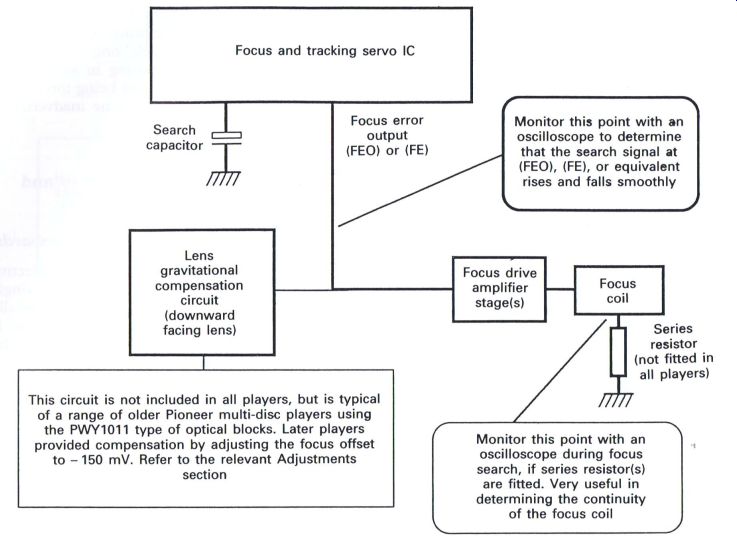
Figure 9.11 Basic focus servo system, showing suggested monitoring points.
...appear to be excessively high or low then voltages within the focus servo, especially relevant positive and negative supplies, may prove to be correct, but also it may prove prudent to ensure that the lens is not mechanically jammed for some reason, preventing correct operation.
Objective lens facing downwards
The optical assemblies that are fitted into players with the lens facing downwards, such as the Pioneer multi-disc and turntable platter players, can make it difficult to observe the movement of the lens, and it may be considered logical to remove the relevant fixing screws for the complete optical assembly and simply turn the unit over to observe the lens movement--take care not to fall into a nasty little trap!!! With this type of player it is possible that some form of correction circuit may be incorporated in Basic focus servo system, showing suggested monitoring points the focus circuits which will provide compensation for gravitational effects upon the lens to enable it to maintain its neutral position. If the unit is turned over to observe the lens movement it will be in effect withdrawn further into the block by gravity, enabling the correction circuit to 'suck' the lens inwards, preventing any hope of monitoring whether the lens is moving correctly or not.
The preferred method of observing the lens in this situation is to remove the relevant screws and just lift the unit vertically a small amount, looking under the unit to check that the lens movement is acceptable. Whichever way the lens may be facing, the majority of players will develop a focus search signal in a manner similar to the block arrangement shown in Fig. 9.1 l, which also includes the possible circuit arrangement to provide any gravitational compensation requirements that may be applicable to relevant players.
Procedure for monitoring the focus search sequence
Players without test or service mode facilities.
1. Without inserting a disc, determine the focus error point, (FEO) or (FE), where possible.
2. Connect the oscilloscope to the relevant point.
Set to d.c., 1V cm^-1, fast timebase to provide a continuous line.
3. Switch on and select the 'play' mode (override interlocks if necessary).
4. The FEO should rise and fall sedately; the number of times will vary depending upon the manufacturer.
Players with test or service mode facilities
1. Without inserting a disc, determine the focus error point, (FEO) or (FE), where possible.
2. Connect the oscilloscope to the relevant point.
Set to d.c., 1 V cm^-1, fast timebase to provide a continuous line.
3. Select the relevant test or service mode facility controls and switch on (see the relevant section in Section 6).
4. Depress the relevant control to commence the search sequence: 'NEXT' for Philips players;
'Track forward' (TRK FWD) or 'Program' (PGM) for Pioneer players.
5. (EEG) and (FE) should rise and fall sedately; the number of times will vary depending generally upon the manufacturer of the player.
If the lens movement is not satisfactory, i.e. it tends not to move smoothly or sedately, it is worthwhile checking the search capacitor and the relevant circuitry for intermittent or dry joints.
Those circuits that have a series resistor included in the ground or return side of the focus coil provide an additional benefit insomuch that monitoring across the resistor with the oscilloscope during the focus search sequence should indicate a rising and falling of the trace, and though of a smaller value, can prove invaluable in determining continuity of the focus coil. If it not possible to obtain this measurement, checks of the focus coil, flexi-print and adjacent circuitry should be carried out.
Is the laser diode functioning? Whilst a laser power meter can provide a useful method of determining whether the laser diode is actually functioning or not, this item of test equipment does not usually appear on the list of required test equipment for many service workshops. This is understandable since access to the laser diode in some types of players can occasionally prove difficult without the need for a certain amount of dismantling; also, many manufacturers recommend the final measurement for laser power being achieved with the use of an oscilloscope monitoring the RF eye pattern waveform.
As a result many engineers are known to check visually whether the laser diode is functioning.
Though the author has never recommended that anyone should visually check the laser diode, he is, on the other hand, quite ready to undertake this task personally. It is essential to ensure that direct viewing of the laser beam through the objective lens does not occur. Warning labels are placed on all CD players at manufacture, and warning information is provided in the relevant service manuals recommending the avoidance of exposure to the laser beam. Though it is possible to observe an amount of faint red light if the laser beam is viewed, this is in fact only a small amount of the laser power; the majority of the laser power is invisible, and it is this that can cause damage to the retina if viewed too closely and for too long. If it is considered necessary to view the laser beam, a few basic guidelines should be followed:
1. Ensure the laser beam is of a low power category; domestic CD players come within this category.
2. View the lens at a distance of no nearer than 40-50 cm.
3. View the lens at an angle of 45 degr.
4. Do not view for longer than 10 s--after all, for how long does a person have to look at a conventional lamp to determine whether it is on or not? It is, however, possible to carry out certain electrical checks to verify that the laser circuit is endeavoring to operate, and the basic block arrangement is shown in Fig. 9.12.
The block arrangement outlined in Fig. 9.12 can be applied to a wide range of players as a basis for typical operation. The LD ON from the system controller will provide a high or low, depending upon the player concerned, though it is usually a high condition and this will in effect switch on the APC circuit.
The laser control transistor will either be a PNP or NPN type, usually depending upon the manufacturer. As a result, the laser diode switch on
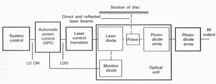
Figure 9.12 Laser control circuit and monitoring points (LDO) signal will
be low for PNP and high for NPN, which will enable the laser diode, which
is usually connected in the emitter circuit, to switch on, therefore resulting
in a high level at the emitter, assuming there is continuity through the
laser diode.
Even though the high may be present and is being applied to the laser diode, and even if there is continuity through the laser diode, it is still possible for there to be no laser light output, due to a lack of emission ability from the laser diode.
It is possible to check whether the laser diode is endeavoring to operate without the necessity of viewing the laser beam, or using a laser power meter, by following the procedure outlined below:
1. Connect an oscilloscope to the RF output test point (the point where the RF eye pattern is monitored).
2. Set the oscilloscope to display a continuous line, and the input to d.c. 0.1 V cm ', using a x10 probe.
3. Insert a CD.
4. Select the 'play' mode.
5. As the player endeavors to 'run up', the oscilloscope indicator should go high with the possibility of an eye pattern appearing.
6. If this does not occur, ensure that the relevant laser diode ON signals are present throughout the relevant sections of the circuit, as shown in Fig. 9.12.
7. This procedure is easier with players that have the facility of the test or service mode, and by selecting the relevant keys that enable the laser diode to operate, the switching signals, as well as the high at the RF test point, should be achieved with a correctly functioning laser diode.
If during this operation, and whilst monitoring the RF eye pattern, the eye pattern endeavors to appear, or there is excessive movement on the oscilloscope due to the appearance of a 'strong' signal, it is possible that the laser control transistor is faulty with a shorted base emitter, or collector emitter connections, either keeping the laser diode ON permanently or causing excessive current to flow when the laser diode is switched on.
As previously outlined in the section concerning adjustment of laser diodes ( Section 6), excessive current through the laser diode can indicate a faulty diode, especially if the RF eye pattern waveform is low compared to the manufacturer's recommended level.
Stage 3: players with the test or service mode facilities selected (with no disc inserted) (See the test or service mode section of Section 6.) See Fig. 9.13.
Philips players: select service mode
Pioneer players: select test mode
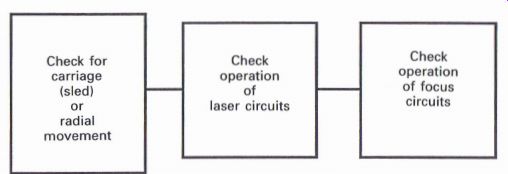
Figure 9.13 Stage 3: carriage, laser and focus checks RE (radial error)
Radial servo system IC
Radial Front panel SySte": Drive
_ or carriage controls _ control amplifier (sled) motor Carriage (sled) servo IC "Stem SLO (sled output)
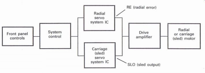
Figure 9.14 Radial/carriage control
Check for carriage (sled) or radial movement
Despite the fact that similar front panel functions can enable the movement of the carriage or radial assembly, the related circuit arrangements are quite different when considering the carriage (sled) operation for the majority of the Far Eastern players, such as Kenwood, Pioneer and Sony to name just three, in comparison to the players that use the Philips radial system. However, Fig. 9.14 endeavors to offer a compromise when it comes to applying some thoughts concerning fault diagnosis.
By referring to the service manual for the player concerned it should be possible to determine the controls that will enable the radial assembly or carriage (sled) motor to move in each direction if the player is capable of operating in the service or test mode.
Philips players:
standby mode, or operate the NEXT key (servicing position I) operate SEARCH FORW. or SEARCH REV.
Pioneer players:
operate MAN. SEARCH FWD. or MAN.
SEARCH REV.
If the radial assembly or carriage (sled) motor fails to operate the following checks should prove useful. By monitoring either the RE (radial error) or SLO (sled output) with an oscilloscope set to d.c. 0.1 V cm ^-1, using a x 10 probe, with a straight line displayed, it should be possible to observe either a high or low level, when compared to zero, when the relevant keys are pressed to move either the radial assembly or carriage (sled) in one direction or the other. These checks should determine whether an electrical fault exists.
Check operation of laser circuits and focus circuits With the facility of the service or test mode it is possible to check the operation of laser and focus
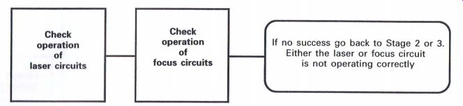
Figure 9.15 Stage 4: laser and focus checks circuits without the need
to switch the player off and on in order that the start-up sequence can
be repeated, by checking the majority of the procedures outlined in Stage
2 with the operation of selected front panel key functions.
* Philips players:
operate the 'NEXT' key (servicing position 1) ,_ Pioneer players:
operate 'Track forward' (TRK FWD) or ' Program' (PGM)
When either of these key functions are selected, the laser diode and focus circuits will function for a brief period of time. As previously mentioned, it is essential that the correct precautions are observed with respect to observing laser beams.
Stage 4: players with the test or service mode facilities selected (with a recommended test disc inserted) (See the Test or Service Mode section in Section 6.) See Fig. 9.15.
Philips players:
operate the 'NEXT' key (servicing position 1)
_ Pioneer players:
operate 'Track forward' (TRK FWD) or ' Program' (PGM)
Operating the specific keys for the relevant player, with a disc inserted, should cause the laser to focus onto the playing surface of the disc.
With single disc and twin-tray players it may appear that not much has actually happened at this stage, but if the disc is gently rotated by hand, a 'squeaking' noise may be heard, which is an acoustic noise from the optical block. This is an excellent method of verifying that the laser and focus circuits are functioning correctly.
With the Pioneer multi-disc magazine players, when the 'TRK. FWD' or 'PGM' keys are operated, the disc from tray 1 will be accepted, and if it remains accepted in the mechanism, this again verifies the correct functioning of the laser and focus circuits.
If no success is achieved at this stage it will be necessary to carry out the checks detailed in Stages 2 and/or 3.
' Stage 5: players with the test or service mode facilities selected (with a recommended test disc inserted) (See the Test or Service Mode section in Section 6.)
See Fig. 9.16.
7. Philips players: operate 'NEXT' again (servicing position 2)
Pioneer players: operate 'PLAY' Note: Always wait 3s after operating the relevant functions outlined in Stage 4 before operating any of the above keys, as otherwise disc 'runaway' is guaranteed.
Disc should rotate at an acceptable speed: check laser power
At this point it is extremely useful to verify that the laser power is correct, by monitoring what
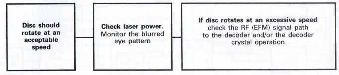
Figure 9.16 Stage 5: checking laser power and initial disc speed
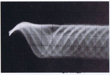
Figure
9.17 Blurred eye pattern waveform is in effect the 'blurred' eye pattern
waveform (Fig. 9.17). This is possibly more relevant to the Pioneer players,
because if the diffraction grating is not correctly adjusted, it will usually
prove impossible to obtain the correct eye pattern waveform, with no sound
output or excessive 'skipping' when trying to operate the player in the
normal 'play' mode. By monitoring the RF eye pattern waveform test point,
the following waveform should be observed, with the oscilloscope set to
either d.c. or a.c., 0.1 or 0.05 V cm ^-1, input, using a X 10 probe,
with the horizontal controls set to 0.5 us cm ^-1.
The amplitude of the waveform should be in the region of 1.2 V to 1.5 V peak to peak, though absolute verification should be obtained from the relevant service manual. Providing this waveform is similar to that shown in Fig. 9.17, it should indicate that the laser diode circuits are operating satisfactorily, and it is always possible to obtain this waveform irrespective of the setting of the diffraction grating, especially with Pioneer players.
If the disc rotates at an excessive speed
Providing that the laser and focus circuits have been proved to be operational, when the 'play' control on Pioneer players has been selected and the disc rotates at an excessive speed it is necessary to ensure that the EFM and/0r crystal clock signals are reaching the decoder circuits, a basic arrangement of which is shown in Fig. 9.18.
The crystal input can either be an actual crystal circuit connected to the decoder or, as in later players which include digital filtering, the crystal circuit may be connected to a different IC with an eventual connection into the decoder.
The presence of a frequency input to the de coder can be monitored with an oscilloscope, using a X10 probe, though for accuracy a frequency counter can be used to determine the actual frequency input.
The RF input to the RF amplifier can also be checked with an oscilloscope, but of course if the disc is excessive or running away, this can prove somewhat difficult, and some form of ingenuity may be required to ensure that a signal from the disc is present.
Typical methods include the following:
1. Connect the oscilloscope to the RF test point, and with a disc inserted select the 'play' function.
Some form of waveform should be present as the player runs up, which will disappear as either the disc reaches excessive speed or the player shuts down because no input is being received by the decoder.
2. With the player in the test or service mode, and laser and focus circuits operating, gentle movement of the disc by hand should indicate that some form of signal from the disc is present.
The EFM output can next be checked usually at the output of the RF amplifier, as the decoder is
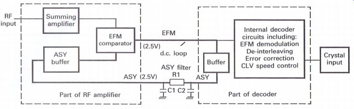
Figure 9.18 ASY circuit arrangement
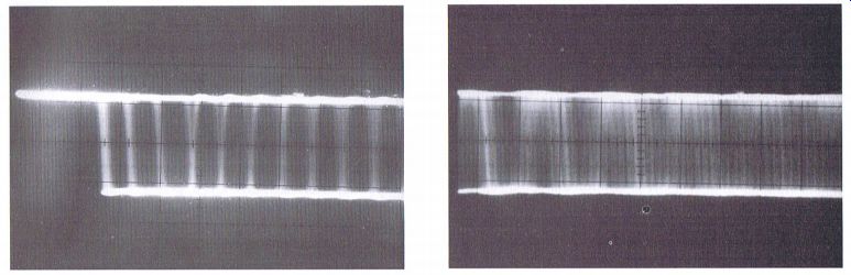
Figure 9.19 EFM waveform usually fitted underneath the printed circuit
board, and a typical signal under normal working conditions is shown in
Fig. 9.19.
A lack of signal here does not necessarily indicate a faulty RF amplifier and the dc. loop, denoted by the thicker line in Fig. 9.18, should be checked, and must be complete for the purpose of the ASY function. Generally speaking, 2.5 V should be present at all the relevant points comprising the EFM/ASY circuit.
Occasions can arise when the ASY filter may cause a problem, preventing the 2.5 V reaching the ASY buffer or EFM comparator, effectively switching either or both off and thereby preventing any EFM output. An interesting feature when monitoring the EFM point, with the player just switched on and no functions selected, is that some form of high frequency can be present, even though the disc is not functioning, which is due to the VCO frequency which will not be locked

Figure 9.20 Unlocked VCO waveform from decoder
being fed back from the decoder towards the EFM output of the RF amplifier
(Fig. 9.20).
Stage 6: players with the test or service mode facilities selected as in Stage 5 This stage can apply particularly to Pioneer players or any players that require adjustment of the diffraction grating. The disc will be rotating at an acceptable speed (see Fig. 9.21).
Check and adjust if necessary the tracking balance adjustment (Refer to relevant Adjustments section in Section 6.) If this adjustment is incorrect, the tracking
---------------------
Check and adjust if necessary the tracking balance adjustment Ensure tracking error waveform amplitude is acceptable Pioneer players:
In the region of 2.0 to 3.6V pk to pk Philips players:
Check diffraction grating adjustment (The grating will not normally change from its original setting, but if the optical block has been replaced the grating may not have been adjusted to the correct point. In the region of 50 mV pk to pk Refer to the relevant Adjustments section)
Tangential/radial adjustments may not be correct (If this is incorrect it is possible that the grating adjustment procedure may not prove successful. Refer to Stage 8 or the relevant Adjustments section)
----------------------
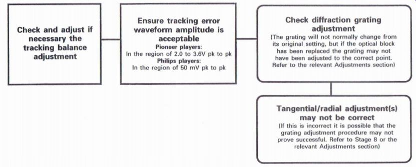
Figure 9.21 Stage 6: checking tracking error waveform and diffraction
grating servo will not operate correctly, and can result in 'skipping'
and 'jumping' problems. By monitoring the tracking error waveform it is
possible to determine how the tracking servo is performing.
Examples of correct and incorrect adjustments are shown in Fig. 9.22.
Stage 7: players without the test or service mode facility (and/or players with the test or service mode facilities selected as in Stage 5)
This stage can apply particularly to those players that have the facility of 'opening' and 'closing' the tracking servo (see Fig. 9.23).
Does the tracking error waveform collapse when the tracking servo is 'closed'? Some method is required to ensure that the tracking servo is endeavoring to fulfill its function in life. This can occasionally be difficult to prove with some types of player, but naturally it is essential for the tracking servo to operate as required, and if the player does not read the TOC at the start of the disc, then a typical symptom can be that the disc tries to run-up and then give up after a brief period (but note that this symptom can also be related to other problems within the player).
Players that have the service or test mode facility can prove easier in determining the tracking servo operation, but it is also possible to briefly verify its operation in the more basic type of players.
Basically the intention is to determine whether the tracking error waveform collapses, which is usually an indication that the tracking servo is endeavoring to operate, and monitoring this waveform can provide the required indication. If the player has the service or test mode facility, follow the procedure outlined in Stages 5 and 6 in order to monitor the radial or tracking error waveform as shown in Fig. 9.24. Providing the waveform is acceptable, press the key that will now close or Operate the tracking servo:
Philips players: operate 'NEXT' again (servicing position 3)
Pioneer players: operate 'PAUSE' The waveform should now collapse to indicate a noise waveform, which is usually an indication that the servo is working.
If the tracking error waveform does not collapse
If the waveform does not collapse, it is usually an indication that the servo is not functioning ...
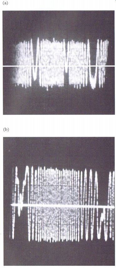
Figure 9.22 Examples of tracking balance waveforms;
(a) out of adjustment and off center, (b) correctly adjusted
...correctly, and it should now be possible to signal trace the waveform, or something similar to the waveform, as a result of further processing in later stages to determine where the fault may be.
Possible causes may be defective radial/tracking coil, broken print on the PCB or flexi print, or defective amplifier stages.
With many players, the waveform is initially monitored at a point before the tracking gain control, if one is present, and it has not been unknown for this control to be set at the minimum setting, which will very effectively prevent the error signal reaching its objective--that phantom twiddler again! Players that do not possess the service or test mode facility require a slightly different approach, and it should be confirmed that the laser, focus and disc/spindle motor circuits are functioning.
Determine a point where the tracking error signal, or its equivalent, can be monitored, and connect the oscilloscope. With a test disc inserted, set the player to the normal 'play' operation.
Usually, as the player runs up, it is possible to observe the tracking error waveform momentarily before the tracking servo comes into operation, at which point the waveform should collapse. If this waveform does not collapse or appears to be present for an excessively long period before the player throws in the towel, then there may well be a problem with the tracking servo Circuits which will need further investigation.
Does the optical block move unexpectedly to one end of its travel? Occasions have been known when the disc appears to run up, and even indicate that the TOC has been determined, but when the 'play' function has been selected, the player refuses to respond accordingly. It has also been known for the optical block, for no apparent reason, to take off towards the outer edge of the disc at the commencement of playing the disc. On such occasions it has proved useful to determine if there is anything wrong with the tracking coil drive and carriage/sled drive stages.
It has been mentioned previously that it is a normal function of the player to ensure that the optical block is returned to the 'home' position, which is usually a function of the carriage/sled motor circuits, which provide a relevant output to bring the optical block to the start position.
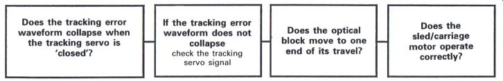
Figure 9.23 Stage 7: checking tracking and carriage operation
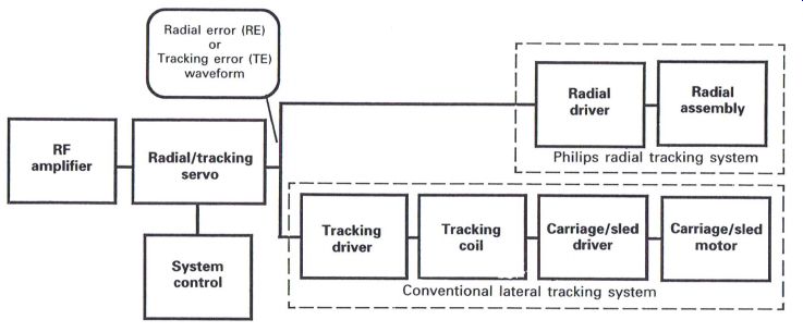
Figure 9.24 Basic radial/tracking servo system block diagram
When in this position the tracking coil can track the initial tracks on the disc to read the TOC without the need to move the optical block.
However, whilst it may be possible to move the optical block in one direction or the other, by operating selected key functions in the service or test mode (refer to Stage 3--Check for Carriage or Radial movement), it is possible that a fault may lie between the tracking coil and carriage drive circuits.
With players that have the service or test mode facility, it is recommended that the optical block is moved to the midway position, though this is not usually possible with the radial tracking assemblies. By going through the process outlined above when determining whether the tracking error waveform collapses, if the optical block goes to one end of its travel when 'pause' is selected, this normally indicates that a dc offset fault may well have occurred within one of the relevant drive ICs. Checks for correct and/or incorrect highs and lows along the servo signal lines, i.e. TE or SLO, should be able to determine where this particular fault may be occurring.
Does the sled/carriage motor operate correctly? Whilst it may be possible with the previous check to determine that the carriage motor is operating correctly, in order that the optical block can travel from the center of the disc towards the outer edge, it is essential to determine that the carriage motor can in fact operate correctly whilst a disc is being played.
As the tracking coil gradually tracks the laser beam across the surface of the disc, it is important that the optical block is moved a small amount in the same direction, before the tracking coil reaches the limit of its travel, as otherwise 'skipping' will occur, creating an effect similar to being stuck in a groove.
By monitoring with an oscilloscope, the supply to the carriage motor, with the oscilloscope set to ...
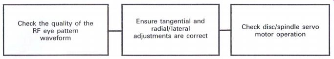
Figure 9.25 Stage 8: checking the RF eye pattern waveform Y = 20 mV/cm
and X = 0.2 ms/cm to 2 its/cm, the resultant trace should appear to be
bouncing up and down when a disc is being played. This bouncing should
have a tendency to move in a negative direction, but can depend upon the
player. As the bouncing moves progressively in the one direction, a point
will be reached when the carriage motor will operate, and thus fractionally
move the optical block. The bouncing level will now reduce in voltage terms,
and then start to increase once again, this process continuing all the
time that the disc is being played.
If the sound starts to 'skip' before the motor moves, then the carriage motor, or possibly the relevant drive circuits, may prove to be defective, but it is also worthwhile checking that there is no unnecessary friction or loading of the carriage mechanics, which would lead to the need for a higher potential to produce sufficient torque to operate the motor.
Stage 8: players without the test or service mode facility (and/or players with the test or service mode facilities selected as in Stage 5) This stage can apply particularly to those players that have the facility of 'opening' and 'closing' the tracking servo. See Fig. 9.25.
Check the quality of the RF eye pattern waveform
Ideally the quality of the RF eye pattern waveform, whilst the disc is being played, should be similar to the waveform shown in Fig. 6.13.
If the amplitude of the waveform is low compared to the manufacturer's recommendation, then the laser power may be low, and should be checked as described in Stage 5 (or refer to the relevant Adjustments section in Section 6).
Ensure tangential and radial/lateral adjustments are correct If either of these adjustments, where applicable, are incorrect this can cause the RF eye pattern waveform to appear low and also out of focus.
Refer to the relevant Adjustments section in Section 6 to achieve optimum results for these adjustments.
If the waveform appears distorted, especially when using a known and reliable test disc, and providing all relevant adjustments are correct, then it is possible that the photo-diode array within the optical block may be faulty, and the optical block may require replacing.
Check disc/spindle motor servo operation
Again by monitoring the RF eye pattern wave form, especially as the disc runs up to speed in the normal 'play' mode, the waveform should effectively 'lock in' almost immediately, but if the waveform appears to be struggling to achieve its normal response, or if there is excessive sideways jitter at the right-hand side of the waveform, then it is possible that either the VCO phase locked loop is out of adjustment (refer to the relevant Adjustments section), or that the disc/spindle motor may be faulty.
Other areas worthy of being checked
1. Are there any mechanical problems in relation to the optical block, i.e. any dried out grease or dirt on the slide bar(s) or thread drive? Check ...
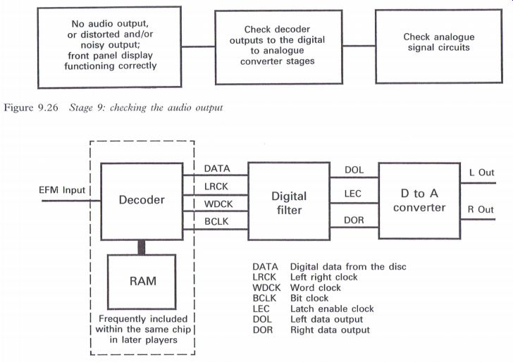
Figure 9.26 Stage 9: checking the audio output
-----------
No audio output, or distorted and/or noisy output;
front panel display functioning correctly
Check decoder outputs to the digital to analog converter stages
Check analog signal circuits
---------
Figure 9.27 Checking the decoder and D to A converter stages
---------
... that the drive spring (if applicable) is correctly fitted.
2. Is the diffraction grating (if applicable) correct (refer to the relevant Adjustments section)?
3. Is the turntable height correct (refer to the relevant Adjustments section)?
4. Check for incorrect electrical adjustments (refer to the relevant Adjustments section).
Stage 9: player operating in the normal play mode--1
No audio output, or distorted and/or noisy output with front panel display functioning correctly With this particular type of symptom (Fig. 9.26), especially the noisy or distorted output, it is the digital to analog stages that have sometimes been suspected to be the problem--often incorrectly. The important indication is that the disc is effectively playing, and that the front panel display is providing all the required indications of track and time information; from this it may be assumed that the greater part of the player is operational, but that the required output is somewhat lacking.
To determine faults within this area, a test disc with a left-only and right-only track can be beneficial.
Check the decoder outputs to the digital to analog converter stages. Fig. 9.27 may assist in determining which direction to take when this particular symptom occurs.
The outputs from the decoder can be measured with an oscilloscope using a test disc, preferably one that includes a left-only and a right-only track, which will prove to be extremely useful in determining possible faulty areas. It is important that the four outputs, DATA, LRCK, WDCK and BCLK, are present as shown though WDCK may not be used with players that use the digital filtering stage.
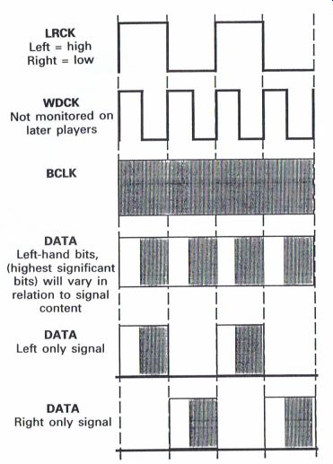
Figure 9.28 Decoder outputs
The waveforms that can be monitored are basically illustrated in Fig. 9.28, together with actual photographic examples (Fig. 9.30), and all waveforms are illustrated with the oscilloscope being triggered by the left right clock (LRCK).
Initially it is important to determine that the four outputs from the decoder (if applicable) are present, as otherwise the subsequent decoding stages cannot function correctly.
By monitoring these signals, it can be determined whether the output signals from the decoder are correct, and by using a test disc with the facility of either a left-only or right-only track it is possible to determine at least in which direction to proceed if the audio output is distorted or noisy.
The appearance of spurious data in the spaces between left-only or right-only data will usually indicate either a RAM or decoder fault. If the RAM is a separate IC it is usually recommended to replace this first, but later decoders usually have the RAM incorporated internally (Fig. 9.29).
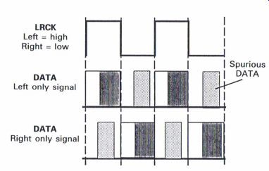
Figure 9.29 Spurious data (noise) from decoder
Further checks at the output of the digital filter enable the following waveforms to be observed which are obtained from a player that has the facility of four times oversampling (4Fs); hence the apparently extra groups of data words when compared to the earlier types of player.
The latch enable clock (LEC), can be either a left right clock (LRCK) or possibly a word clock output (WCKO), depending upon the type of player and which ICs are being used in the data processing stages. The purpose of the LEC is to enable the D to A converter to commence its operation correctly (Fig. 9.30(a)-(f)).
If there is no audio output or a distorted audio output
Providing the previous waveforms, whichever are applicable, are correct and are being applied to the initial AF pre-amplifier stages, further monitoring should enable the faulty area to be determined, and. by using a tone from the test disc it is also possible to determine whether distortion is being caused by these stages.
It is possible that either the muting or deemphasis circuits are causing a problem. The DEMP and MUTE control signals usually originate from the system control circuit, and whether they are high or low will obviously relate to the type of circuit in which they may be operating.
The DEMP (de-emphasis) is not relevant with all discs, and it may be necessary to determine whether this circuit is operating or not by using a test disc that has tracks with emphasis included; these may be determined from the notes usually supplied with the disc (Fig. 9.31).
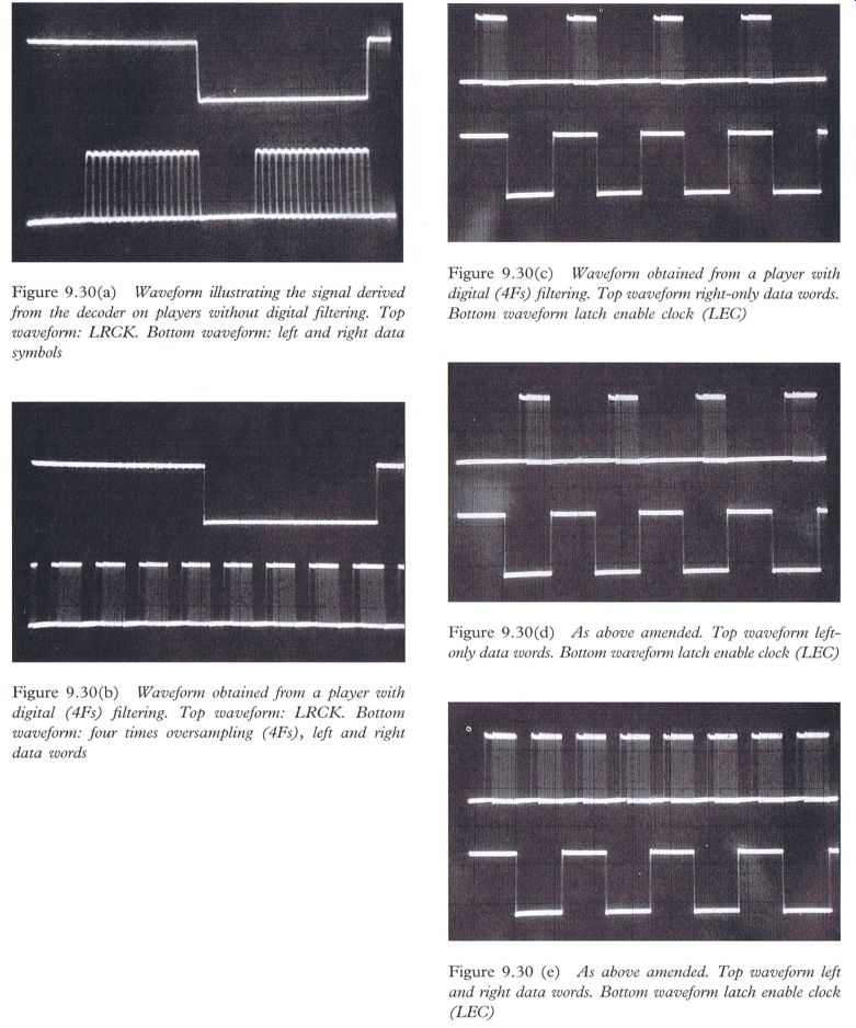
Figure 9.30(3) Waveform illustrating the signal derived from the decoder
on players without digital filtering. Top waveform: LRCK. Bottom waveform:
left and right data symbols Figure 9.30(b) Waveform obtained from a player
with digital (417$) filtering. Top waveform: LRCK. Bottom waveform: four
times oversampling (41%), left and right data words
Figure 9.30(c) Waveform obtained from a player with digital (4FX) filtering. Top waveform right-only data words.
Bottom waveform latch enable clock (LEO) Figure 9.30(d) As above amended. Top waveform left only data words. Bottom waveform latch enable clock (LEC) Q Figure 9.30 (c) As above amended. Top waveform left and right data words. Bottom waveform latch enable clock (LEG)
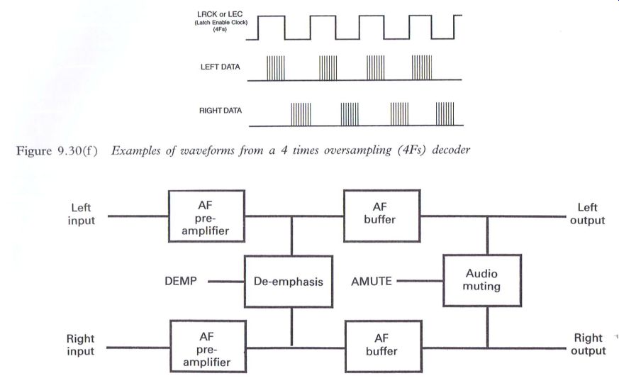
Figure 9.30(f ) Examples of waveforms from a 4 times oversampling (4Fs)
decoder
Figure 9.31 De-emphasis and mute control The MUTE control will usually switch on the relevant transistor circuits to prevent unnecessary audio output, and checking of these stages should prove relatively straightforward.
Stage 10: player operating in the normal play mode—2
There is audio output, but the player appears to 'skip' and/or 'jump' whilst playing the disc
Of the many and various faults that can occur with CD players, the 'skipping' and 'jumping' problems tend to be amongst the most common, and of all the faults that can occur these particular problems can frequently prove to be the most difficult to determine.
Many engineers will have experienced a customer who is emphatic that whilst the discs 'skip' and 'jump' on his or her own player, they naturally operate quite satisfactorily on any other player--especially on the one next door! The initial recommendation is that when the player comes in to the service center for investigation, ensure that a selection of the offending discs is also supplied. It is also useful, if the facilities are available, to allow the customer to demonstrate the specific problem.
Check the quality of the disc being used
Those early television Programs displaying the virtues of the CD with the dreaded raspberry jam demonstrations still have a lot to answer for, and whilst the CD is an excellent format in many ways, it should, ideally, be handled in the same manner as the ever faithful vinyl record. Frequently, CDs that customers expect to use in their players appear to have had alternative existences as either coffee, tea or beer mats, as well as having ...
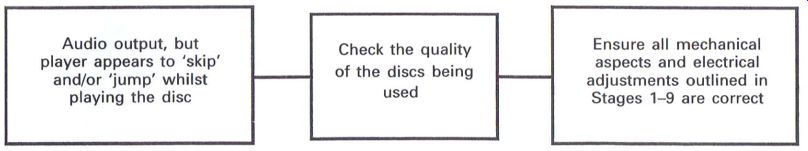
Figure 9.32 Stage 10: checking for skipping and jumping
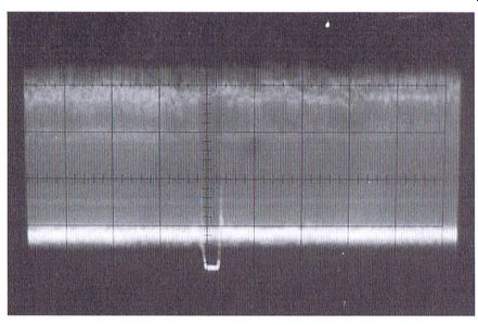
Figure 9.33 Compressed eye pattern waveform showing excessive scratches
on disc. Smaller scratches (not shown) can also be observed with this method
been used as a 'Frisbee'. When a comment is made with regard to the quality
of the disc, the reply is frequently along the lines of: 'You can do anything
with a compact disc . . . they said so'. In response to the further enquiry
as to who 'they' might be, there is usually a reference to the dreaded
TV Program and raspberry jam.
If a player does appear to be playing a disc as though it is stuck in a groove, and especially if it is consistent on a specific disc at a particular section or time, then it usually goes without saying that the disc must be checked first. If it is just a question of dirt, then gently cleaning the disc with warm soapy water will cure most ills, and gently polishing off with a clean soft duster should restore normal operation. A quick lick and polish up on the front of a shirt is not really to be recommended ... it has been observed! If the disc is scratched, more drastic action is needed depending upon the severity of the scratch.
Whilst success can be achieved in most cases, a severely scratched disc can still create problems, even if the scratch appears to have been removed and is not visible to the naked eye.
Many engineers have their own favorite method of removing scratches, often including light abrasive creams such as perspex polish, soft toothpaste (not your denture cleaning type), and silver polish; whilst Brasso is excellent for the more desperate, car polish and the buffing wheel are definitely not recommended.
It is important when polishing out any scratches that a technique is developed of using either small circular strokes, or strokes that are at right angles to the track. This is because the action of polishing the disc in this manner in itself creates extremely fine scratches, which providing they are at right angles to the track can be compensated for by the error correction process within the decoder. But the ideal is to get the disc back to its original condition, which may prove extremely difficult. If the disc is cleaned in large circular strokes, fine scratches will occur that will in part be parallel to the track which in turn will cause tracking problems when the disc is played.
On completion of any scratch removal process, it is again recommended that the disc be gently washed in warm soapy water to remove any residue from the cleaning agent, which if it is oily or greasy in nature can affect the optical characteristics of the disc, and create continued problems.
It is also useful to monitor the RF eye pattern waveform to determine disc quality, and this will be explained in the following section.
Ensure all mechanical aspects and electrical adjustments outlined in Stages 1-9 are correct
Assuming that the disc quality is proved to be satisfactory, various aspects of the adjustments that are applicable to a particular player must now be considered. Some that can create 'skipping' and 'jumping' problems are highlighted as follows:
Mechanical
1 Ensure all slide bars are clean and free from dried-out grease.
2 Check the disc turntable is set to the correct height.
3 Check that any drive springs that may be fitted are correctly located.
4 Check that the optical block flexi-print is correctly formed, and not creating any restriction of movement.
5 Ensure that the complete optical assembly is correctly located, and any resilient mounts are properly fitted.
6 Tangential and lateral/radial adjustments (if applicable).
7 Incorrect grating adjustment (if applicable).
8 Check for a defective disc/spindle motor.
9 Check for a defective carriage/sled motor.
Electrical
1 Check for an incorrect RF level (eye pattern waveform), i.e. not too low or high.
2 Check for incorrect focus, tracking and RF offsets (if applicable).
3 Check for incorrect tracking balance adjustment.
4 Check for a wrongly set VCO.
5 The focus and tracking gain may be incorrect.
6 Check the quality of the RF eye pattern waveform.
Occasions have been known where everything has seemed to be absolutely satisfactory, both mechanically and electrically, and the last resort has been to replace the optical block, but from the author's point of view this should be the last resort, as the previously outlined recommendations resolve the majority of the 'jumping' and 'skipping' problems.
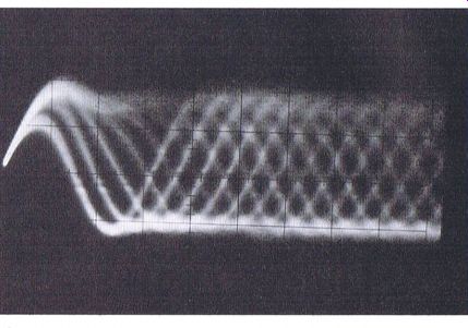
Figure
9.34 RF eye pattern waveform from a poor quality disc Quality of the RF
eye pattern waveform The ideal waveform is shown in Fig.
6.13, but if the
quality of the reflective surface is poor, and this can be in relation
to the actual quality of the 'pits' or 'bumps', then the waveform will
suffer accordingly. Fig. 9.34 shows the RF eye pattern waveform obtained
from a poor quality disc that has been played without any major problems
on many players, but which is illustrated to show how the quality of a
disc may be determined by monitoring this waveform.
Excessive vertical bouncing of the waveform, compared to a known reliable test disc, can be due to excessive disc eccentricity, which again can result in 'jumping' and 'skipping'.
By compressing the timebase range on the oscilloscope to ~ 2 ms cm^-1, it is possible to actually monitor scratches on the surface of the disc whilst it is being played. This can give some idea as to how the player is being required to handle the 'glitches' that can be caused with scratched discs, as shown in Fig. 9.33.
------------------