False Leakage Indication
This suggestion was prompted by a technician of our acquaintance, who recently complained that he was finding plenty of leaky capacitors in various circuits in the course of troubleshooting, but that replacing them would not correct the complaint.
A few leading questions soon disclosed that the so-called leaky capacitors were not being tested with a condenser checker, but with the time-tested expedient used by many servicers and illustrated in the accompanying figure. In this method, the grounded (or more negative) end of the suspect capacitors is disconnected, the voltmeter is inserted at the point of this break (marked "X") , and the receiver power switch is turned on. The presence or absence of a dc voltage reading will respectively indicate whether the condenser is or is not leaking. Since an amplified signal or pulse is present at the plate of the tube, and since this signal is ac, it will pass through the coupling condenser. Although it is ac, it may give a false dc meter reading, often indicating leakage where there is actually no leakage at all.
To eliminate confusion in conducting this test, proceed as usual but remove the tube associated with the condenser from its socket. This removes signal, but leaves B-plus on the plate side of the capacitor. Airy reading on the dc ranges of the meter will then definitely indicate leakage rather than the presence of signal.
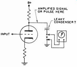
------- Time-honored leakage test gives false reading.
HV Condenser Check
To find leaking condensers of the 500-mmfd, 20kv type rapidly and easily in the high-voltage power supplies of some TV sets, I use the following procedure: Take a wooden stick, rod or rule about 20 or 30 in. long and fasten a small square of cardboard at one end. This end is used as an earphone. Then apply the other end near the suspected condensers. The clearest noisy clicks will be heard when the stick is closest to the bad condenser. The trouble appears as black pips or streaks on one side of the screen at the same time that the clicks are heard. The wooden rod used must be very dry, to act as a good insulator and also to pick up the sounds better.
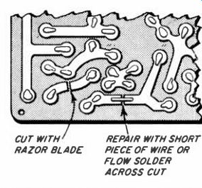
------ Components in PC are quickly isolated for testing by cutting with
razor blade.
Testing PC Components
A problem encountered in troubleshooting printed circuits, as compared with conventional hand-wired sets, is the difficulty of isolating a stage drawing excessive current because of a leaking or shorted component. For example, if an I-F transformer is suspected of high resistance leakage it is not practical to remove the transformer from the board merely for testing or for a substitution check.
Another example is where a transistor drawing excessive current is soldered into the board. The transistor may be ruined if removed for a check or substitution.
In all cases I use a very sharp, thick type, razor blade to cut through the printed circuit foil. The I-F is cut from ground and the emitter of the transistor drawing excessive current is opened (or one of the other elements, depending on transistor type and application). After checking a component, this narrow cut in the printed circuit is then easily bridged with a piece of tinned hook-up wire, or in the case of low current lines, with only a bit of solder flowed across the cut, as shown at left. This system often prevents unnecessary loss of time.
Upside-Down Tube Test
This experience suggests some interesting possibilities for the correct use of tube testers. A Motorola car radio was brought in for repair and restored to perfect playing condition on the bench, then returned to the owner's auto. In a few days, the set was brought back to the store with the complaint that volume would drop when the set was jarred. More jarring would restore the volume.
With the set in normal position on the service bench, nothing could be found wrong with it. All tubes were checked out and found to be in good condition. However, this set happens to mount upside-down when installed in the car, with the tubes pointing downward. Turning the set upside-down in the shop, the intermittent volume could be induced by tapping the chassis. Now, turning the tube checker upside-down enabled a testing of the tubes in the same position they occupied in use in the auto! Sure enough, two tubes showed up as defective in the tube checker when held in this position, although they had checked out in the upright position.
Voltages from Old Tester
Tube testers that may be obsolete for checking modern tubes are still worth keeping around the shop. A low voltage of some odd value is often required, as for testing an instrument over a range of scales. The obsolete tester can supply a considerable range of such voltages by merely attaching test leads to the filament terminals of one of the sockets, as shown, and adjusting the instrument for the proper value.
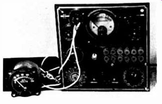
---------- Outdated tube checker as low-voltage supply.
Meter Checks Fuse Blowout
A 300-ma meter, which can be conveniently and compactly carried on service calls, may be used for determining the cause of fuse blowing in the high-voltage section. First clip the meter leads to either end of the fuse holder, with no fuse in the circuit, and turn the set on with one hand on the power cord. If the meter needle starts to swing up fast, a direct short is indicated, and the plug must be pulled out of the wall socket immediately.
In most cases, the set lights up and works with the meter being used instead of the fuse. Normal current will be about 75 to 100 ma. Next the damper tube is tapped. If this procedure results in a kick of the meter needle, the indication is that the damper tube is intermittently shorting and should be replaced. In other cases, the filament wiring of the damper may be shorting to chassis due to insulation breakdown, especially where the damper cathode is tied to the filament. This will show up when the set is jarred. By using the meter as a temporary replacement for the fuse, a considerable amount of assurance is provided that there will not be repeat blowouts, since the cause of fuse failure can usually be found and corrected.
Another use for the meter, while it is connected exactly as already described, derives from the fact that it is in series with the boosted B-plus line. Other circuits that receive B-plus from the same point may also be checked. For example, if the horizontal oscillator is getting B-plus from the damper, it is easy to determine whether the oscillator is functioning. If the oscillator tube is pulled out of its socket, there should be an increase of current (about 5 to 10 ma). This change will occur if the oscillator is functioning. If the oscillator is not working, no change in current will be noted, as there is no change in the amount of current being drawn by the output tube.
Capacity Readings With a VOM
A quick and inexpensive measurement of capacity can be made with your VOM or VTVM and a potentiometer. The device may also be used to match or pair new components. It consists of nothing more than your meter, an extra pair of leads and a linear potentiometer on the order of 1 megohm. The value is not critical. The only precaution is not to exceed the wattage and current rating: as the control is placed directly across the AC line. The hookup is shown in the diagram.
Even the line voltage is not critical. The important thing is to establish full scale deflection, using the AC function and proper rank. This is accomplished by shorting the test leads, at the points marked X and adjusting the pot. Graphs and charts could be plotted, but this is not necessary. To calibrate the meter, note the readings obtained from capacitors of known values. By using different potentiometer values and different AC ranges, it is possible to obtain a fairly wide range of measurement. However, once the range and resistance have been selected and adjusted the scale will remain accurate.
The above arrangement may also be used to determine the values of coils, chokes, yokes, etc. If 400-cycles, available on most signal generators, were used instead of the 60-cycle line voltage, even more accurate and wider range of readings would result.-ED.
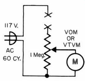
---- Divider network permits reactance readings.
Quick AC Outlet Test
For testing ac lines in the customers' homes, technicians can easily carry along one of the small 2-watt neon "Nite-Lites," available at all dime stores, that plugs directly into the ac outlet. When the complaint is total in operation, one of these units, which can be carried in a vest pocket, will give an instantaneous indication as to whether the ac circuit is alive. It's better than asking the customer for a bridge lamp.
Scope Graticule Retainer
While visiting several technician friends, I noticed they were encountering a problem that previously troubled me for a while. The calibrated grid screen or graticule, in front of the scope CRT, frequently becomes tilted and even falls out at times.
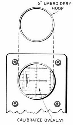
----- A wooden embroidery hoop fits snugly against scope graticule and
prevents its shifting or falling out completely.
Purchase a 5" wooden embroidery hoop (about l5(' in a sewing shop) and fit the ring against the graticule, as illustrated above. It fits snugly, and retains the graticule firmly in place.
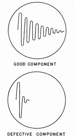
---------- Good parts show prolonged ringing. Fewer oscillations occur
when shorts are present.

--------- Set scope's sweep rate for part being tested.
Scope Checks Horizontal Components
A defective horizontal output transformer, yoke or coil in the deflection circuit of a TV receiver can sometimes be difficult to diagnose.
(Usually substitution with a good component is the only sure method.) An open winding is easy to check but shorted turns are not so easy, resistance measurements are not always conclusive.
The following method of checking horizontal deflection components will indicate shorted turns without removing the component from the circuit, with the receiver turned off.
The individual component (or complete horizontal deflection system) is connected to an oscilloscope probe with a pulse (supplied by the oscilloscope) connected to the same point.
A waveform can then be produced that will look like the illustration if the component is good or bad.
To check a component. connect the scope's probe to one end of the coil and the probe's ground lead to the other end. Connect this pulse to the scope's probe. Adjust the horizontal sweep frequency of the scope according to the table.
A complete receiver deflection system may be checked by removing the plate cap of the horizontal output tube and connecting the oscilloscope probe and pulse to the cap lead of the transformer. Connect the ground lead of the probe to the receiver chassis. One shorted turn of the horizontal output transformer will produce the short, damped waveform characteristic of a defective component. The effect of shorted turns may be seen by shorting the filament winding of the horizontal output transformer while checking the transformer with the scope.
To obtain the pulse from an oscilloscope a small modification is necessary that will not affect performance.
Remove the "GROUND" binding post on the front panel that is farthest from the vertical input attenuator. Enlarge the hole in the front panel and replace the binding post using fiber washers to insulate it from the panel. Connect one end of a 680 mmf. capacitor to the binding post. The other end is connected to the cathode of the horizontal sweep oscillator.
Capacitor In-Circuit Test
Most applications, of bypass, coupling and filter capacitors, for practical purposes, present a short circuit, or very low impedance path to ac. Therefore, the voltage drop across them should be zero or very low. Measuring the AC voltage drop across the capacitors will usually indicate whether or not they are open or have decreased in value appreciably. There is one notable exception-a low AC voltage reading of about 10 to 15 volts is normal across the input-filter capacitor in a B-L capacitor input filter circuit. Most filters of this type have a high ripple content at this point.
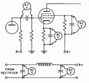
------ Measuring AC voltage drop across capacitor to predict condition,
while in circuit.
Quick Testing Phototubes
A quick way to test photo-electric tubes, especially the emission type is to place it approximately 1 foot away from an unshaded 75-watt incandescent lamp. Position the tube so that the cathode is exposed to the light. Place the positive test lead of an ohmmeter on the anode and the negative lead on the cathode of the tube. Set the ohmmeter scale to R X 10K. The readings may be somewhere in the region of 150.000 to 800,000 ohms. Next shiel3 the tube, and the reading should rise to about 10 megohms. Another check is to reverse the test leads on the tube, an extremely high reading should he obtained. Some typical values are:
Tube | Type | Age | Resistance
918 Gas New 145,000
923 Gas New 220,000
868 Gas New 800,000
929 Vacuum Used 145,000
A good idea is to check each new phototube type in this manner, and record the readings for future reference. While this type of test is not the most scientific one, it is simple, quick and does seem to work out well. Similar tests can be set up for the photo-voltaic and the photoconductive cells.
Checking Open W-W Resistors
The next time you run into one of those sand-coated wire-wound resistors that has opened up, and you have no way of checking its value, try this procedure. Take a pair of diagonal cutters and use them to crumble off the coating along one edge of the resistor. This should be done with care, of course, so as to avoid any damage to the wire resistive element beside the damage that already exists, the open condition.
Now connect one lead from your ohmmeter to one terminal of the resistor. Slowly slide the other probe of the meter along the wires you have just bared, beginning near the terminal to which the other probe is connected and working away from it.
As you do this, the resistance reading should start at zero and increase until you reach the point of the break, at which point the reading will shoot up toward infinity.
When you have reached this point of the break, record the highest reading obtained just before the break became evident, and then switch the fixed meter probe to the other terminal on the resistor. Now begin the same procedure from the other end of the resistor. That is, slide your free probe along the exposed portion of the resistor, beginning near the terminal to which the probe is now fixed, and moving away from it.
Again, the reading will shoot up suddenly when the point of break is reached. The highest reading found on this side of the resistor just before the break is reached is added to the highest reading recorded on the other side. The sum of these gives the original value of the resistor before it became open.
--------- Completed version of color CRT test adapter.
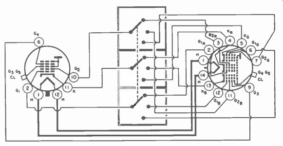
--------- Schematic for color CRT test adapter showing simplified version
of socket connections.
Color CRT Test Adapter
Versatile tester will check color CRT's on B&W tube checker, or regular tube checker with adapter. Simplicity, ease of construction and low-cost features make this a desirable project between service calls.
Extremely flexible it tests each section of the color CRT individually. A 3-pole, 3-throw rotary switch (Mallory #1313L) is the heart of the gadget. It is enclosed in a 2 1/4" x 2/" x 3" box. A Motorola color CRT socket part number 733,794 is available already wired. The wires are fed into the box and protected with a rubber grommet. A 6-pin CRT base removed from a dud, is mounted on the box by drilling a small hole through the key projection and bolting. In addition to the small hole drilled in the box to accommodate the bolt, another hole is needed to allow the wires to pass through. Again it is advisable to use a rubber grommet. The electrical wiring is simple and is easily determined from the diagram. As a finishing touch a CRT-base cover is used to protect the pins while the gadget is in the tool kit.
Life Saver
A great many TV receivers, especially portables, have been sold which are enclosed in metal cabinets. All service technicians realize the potential shock hazard this poses, but few check to see if the cabinet is "hot" upon completing a repair. Receivers that utilize a power transformer are not as dangerous as the ac/dc variety, but even a transformer type chassis bypasses the line to chassis with capacitors which may short. The chassis in portable receivers is mounted on insulators, but a splash of solder or a chassis bolt which is too long may easily defeat their purpose. A common sight is to see portable receivers going out of repair shops in good operating condition, but missing a few knobs. These exposed shafts may be 115 volt electrodes, depending upon how the line plug is inserted.
Illustrated is an inexpensive tester I constructed which will quickly locate a "hot" cabinet. The circuit is relatively simple and needs no explanation. To use the tester with toggle switch in position #1, the test probe is simply brought into contact with the metal cabinet and the pushbutton pressed. This is repeated with the toggle switch thrown to position #2. If the indicator lights in either position it indicates a "hot" cabinet. The set's line plug does not have to be reversed as this is, in effect, accomplished by the tester switch. I suggest using a 3 watt 115 volt bulb as an indicator as this will show a leakage as low as 10 ma. I used a bulb as an indicator rather than an AC voltmeter not just because it's cheaper, but because a voltmeter sometimes gives an ambiguous indication on sets which have the chassis connected to the cabinet through an R/C network.
This tester can be built in a three inch square housing and permanently attached to the test bench.
For safety the press-to-close pushbutton switch in series with the probe allows AC on the probe only when in use. This tester can also be used with radios and appliances where there is a possible shock hazard. The tester can be constructed for less than $2, but if you find just one "hot" cabinet with this tester it may become the most priceless piece of equipment in your shop.
Dynamic Condenser Check
In many instances, condensers short only under load, and check ok when out of the circuit. When such a condition seems to be present, I use a voltmeter in series with the suspect part, as shown in the illustration. If the capacitor is shorted, a dc current flows through it and through the resistance of the meter.
This sets up an IR drop, and the meter needle will swing up, verifying the existence of the short.
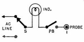
------- "Hot chassis" checker helps unmask those 115 volt electrodes.
Parts list: Ind.-3-watt, 115v bulb; J-probe jack; S-SPDT toggle; PB-normally
open, press-to-close switch.
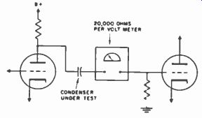
--------- Checking capacitor dynamically with voltmeter.
Salt Wafer Test Battery
The photograph shows the two leads from a meter immersed in a salt water solution. The meter is set on its 60-microamp scale. The current reading on the meter is about 20 microamp. This small home-made salt-water battery is excellent for testing' meters, such as milli-ammeters and micro-ammeters, as there is practically no possibility of damage to the meter movement due to the low output from this type of rudimentary battery.
The movement of nearly any device that uses a meter can be checked with this salt-water tester.
The meter movement of a photoelectric exposure meter, for example, can also be tested in this way. It is a good idea to use a silver coin and a length of copper wire as the two electrodes in this solution, connecting each of these to one of the leads from the meter for the test.
Stop Tube Tester Wear
One of the annoying jobs we run into is the continual changing of worn out tube sockets in our tube checkers, a tough and time-consuming task. I have found that, by plugging a tube-testing adapter into each of the more frequently used sockets of my tester (see photo), I save this time. A small amount of service cement is used to hold the adapter firm. When the socket in the adapter itself is worn out, simply pull it out and insert a new one. The time saved more than compensates for the cost of the adapter.
Preventing Instrument Damage
Plastic or wood cases of various test meters are so smooth that the instruments are easily pulled from the bench during use. A few layers of adhesive tape placed on the bottom of the case will often remedy this kind of trouble. Tape also may be installed in a criss-cross manner to further prevent slipping.
--------p69 Salt water battery tests meter movements.
--------p69
-------p70 Simple diode checker and typical waveforms.
-------p70 Rapid location of tube data on a roll chart is facilitated by enclosing frequently used tube designations with red pencil marks.
Diode Checker
This simple diode checker may be used with any oscilloscope. The technique is interesting and accurate.
The input signal is not critical. About 2.5-volts ac is all that is required.
Any low-voltage transformer may he used. The plate side of an audio output transformer may be connected to the AC line. The secondary winding usually develops about 2.3 volts. Because there is practically no load, the size of the transformer is not a factor. The only other parts needed are a 1,000-ohm, 1-watt resistor and some terminals. The entire unit could be built into the scope.
Calibration consists of comparison with a unit known to be good. Crystal diodes may he checked for match, open, shorts, high or low impedance, and ability to rectify. Diagram shows typical waveforms and schematic.
Faster Tube Tester Set-Up
Roll charts on roll-type tube checkers grow longer every year, making it difficult to quickly locate a particular tube type.
I've abbreviated this time-consuming process to a great extent as follows: When installing a new tube checker roll chart, mark the designations of the most frequently used tubes on the roll. When the roll chart is spun around to locate the tube type and tube checker settings, the marked designations aid in rapidly locating the desired information. The tube numbers are either underlined or boxed in with a red pencil, as illustrated below. This is done after installation of the roll chart, but before placing the roll back in the case.
Stand for Shop Meter
So that our meters don't get lost in the confusion of littered benches and so that we don't have to crane our heads around the corners of TV chassis to see the readings, we keep our meters parked atop rocking-chair wood stands, like the one in the photo. The backs of these stands are tilted back to slope the meter's scale upward toward eye level. Attached to the bottoms are small metal buttons so that the stands can glide easily across the surface of the shop benches.
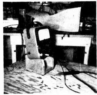
--------- "Rocking-chair" stand makes meter handy.
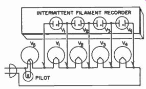
--------- Intermittent filament recorder.
Intermittent Filament Recorder
Four neon test lamps, mounted in a small box, plus five test leads is all that is needed for finding an intermittent filament in an AC/DC radio.
Place the leads across the tube filaments as shown in the diagram. Turn on the radio and allow it to play.
When the filament circuit is interrupted, the neon light connected across the break will glow. In the event none of the lights go on, when a break occurs, then it can be assumed that the rectifier tube is the culprit. The beauty part of this procedure is that the technician is free to work on other equipment while the radio under test is in working order.