The basic single tubes (valves) grid leak detector with reaction receiver described in the previous section is capable on its own of giving acceptable results for anyone willing to listen only with headphones. However, since most of us prefer to use loud speakers, more tubes (valves) have to be employed to amplify the output of the detector suitably; this subject has already been covered in Section 7. In theory it would be possible to add as many stages of amplification as necessary to make even the weakest of stations audible through the loud speaker, but in practice this would be unsatisfactory. An ordinary grid detector, even with reaction, still has relatively poor selectivity, that is, the ability to pick out a desired Station cleanly from all the others arriving at the aerial. The result on weak stations is that they may well be interfered with by more powerful ones on neighboring wavelengths. To overcome this the tuning has to be ‘sharpened’ and a relatively simple method of achieving this with a tuned circuit preceding a detector is to make it the secondary of an HF transformer, with the primary used to couple the aerial inductively instead of directly. An extension of this is to use two sets of HF transformers, one in the aerial circuit coupled to another feeding the detector and with each having its own separate tuning capacitor. Properly designed this arrangement would select only a relatively narrow band of frequencies, hence its generic name of ‘band-pass’ tuning. Better-class receivers continued to use it right through the vintage radio era.
Whilst improving the tuning enables particular stations to be selected more easily it is not a complete answer to receiving those situated at a long distance from a receiver, for any remaining interference will be amplified along with the required AF. A far more effective and satisfactory idea is to amplify the RF signals from the transmitter before detection. This could be achieved by using separate RF transformers to couple one or more triode amplifiers in sequence and then to the detector; as each transformer would have its own tuning capacitor the selectivity would also be greatly improved. Sets which use one or more RF amplifiers before the detector are known generically as tuned radio frequency (TRF) receivers, or sometimes colloquially as ‘straight’ sets.
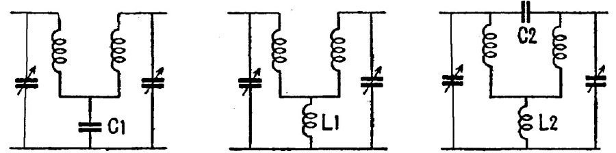
FIG. 1 Three forms of band-pass tuning using (from left) capacity coupling,
inductive coupling and a combination of the two.
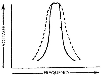
FIG. 2 Response curve of a band-pass tuner (solid line) as compared with
that of a single coil and capacitor (dotted line).
Unfortunately triodes will not work satisfactorily as HF amplifiers above about 100 kHz, after which they become unstable. As when any metal objects are held in fairly close juxtaposition, a certain amount of capacity exists between the various electrodes of a valve. These internal capacities are small enough to be negligible at fairly low frequencies but above the 100 kHz mark they become more and more significant until they start to introduce instability and even self-oscillation into an amplifying stage. A part-answer to the problem was to fit small variable capacitors between the anode and grid of HF amplifiers to oppose and cancel out the internal capacities. This process, called neutralization, was used with varying degrees of success (often dependent on the skill of the listener) for some years, but even at best a triode can give only a relatively small overall gain at HE.
Really stable and effective HF amplification had to wait until the introduction, in 1926, of the screen-grid valve. This has a second grid inter posed between what is now called the control grid and the anode. This new grid literally acts as a screen between them and reduces the internal capacities. It is operated with positive HT applied, the voltage being between about half and the same as that on the anode. Extremely large stage gain figures may be realised with screen-grid RF amplifiers, a single one being sufficient for many receivers. Because it has four electrodes the screen grid is properly called a tetrode, but this term was not widely used in vintage radio literature; far more popular was the abbreviation s.g. valve.
It is fair to say that the s.g. tubes (valves) revolutionized TRF receiver design but it is not without its faults. In use the anode itself emits electrons caused by its bombardment from the filament or cathode. This secondary emission, as it is called, tends to collect on the screen grid and brings about a strange non linearity in the current drawn by the latter and by the anode. As FIG. 3(a) shows, there is a pronounced kink in both at a certain combination of voltage and current which has the effect of making the s.g. tubes (valves) unsuitable for other than RF amplifiers. Subsequently yet another grid was added, this time between the screen grid and the anode, which had the effect of suppressing the secondary emission from the latter, thus giving it its name of suppressor grid. In operation the suppressor is connected to the filament or cathode, to which the secondary emission is returned harmlessly. This new five-electrode tubes (valves) or pentode is extremely suitable for both RF and AF amplification and as a power output valve. It offers good sensitivity and linearity and rapidly became almost supreme in these fields. Its only serious challenger was a development of the screen-grid tubes (valves) in which the spacing between the electrodes is critically adjusted to cause the electron stream from the filament or cathode to travel in sharply defined beams rather than in random formation. Known as the beam tetrode or kinkless tetrode, this type of tubes (valves) has characteristics similar to those of the pentode and in many cases they are interchangeable in receivers.
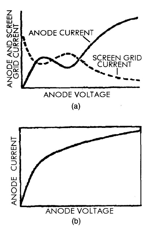
FIG. 3 (a) The characteristic ‘kink’ in the screen-grid valve’s current vs.
voltage curve (b). However, the pentode has a nice linear curve.
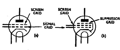
FIG. 4 Theoretical symbols for (a) screen-grid and (b) pentode tubes (valves).
Sharp cut-off versus variable mu
A major problem with the s.g. valve, the pentode and the beam tetrode was that in RF amplifiers their high gain could, in certain circumstances, be a drawback rather than an advantage. It was extremely useful for receiving weak stations but when the set was then tuned’ to powerful locals severe over-loading took place. The gain could not be reduced by putting extra negative bias on the control grid because all these types of tubes (valves) have what is called a short grid base or sharp cut-off whereby the anode current drops to zero at very little more than the normal value of operating grid bias. It was found that by winding the control grid in a certain way the grid base could be lengthened very considerably, with the cut-off bias being increased to as much as —40 V below the operating voltage. By varying the grid bias between these points the gain of the tube (valve) could be controlled very accurately, giving rise to the term variable-mu tubes (valves) (remote cut-off in the USA). To distinguish them, non-variable-mu types are called straight tubes (valves).
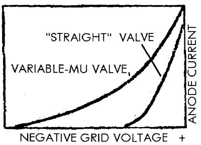
FIG. 5 Comparing the slopes of typical ‘straight’ and variable mu tubes (valves).
Extending the tuning range
Early receivers, of which there are still thousands in circulation amongst radio collectors, employed separate coils with different numbers of turns to cover different wavebands. Anyone engaged in repairing radio sets is almost certain to encounter one of these at some time or other. Coil changing did not appeal to non-technical listeners and a much more convenient development was to wind several different coils on one former each for a certain band, and to select them as required by means of a switch to obtain coverage of a desired band. This feature was universal in commercially built domestic receivers by 1930. Initially only medium and long waves were covered: note that some sets in this class had the waveband switch marked ‘short’ and ‘long’, which could be confusing to the beginner. From about 1935 growing interest in true short waves led to many firms including an SW band in even cheap receivers, the usual coverage being from about 16.5 m to 52 m.
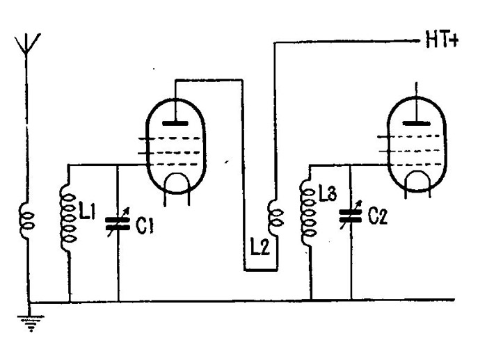
FIG. 6 Basic two-stage RF amplifier using pentodes, for one band only
Also by this time the pentode was beginning generally to take over from the triode in output stages, where it offered good sensitivity and output power with reduced HT current consumption. Its only drawbacks were that, having a high internal resistance, it could not be coupled directly to a loudspeaker and a matching transformer had to be employed: in addition it tended to favor the higher AFs and to give rather shrill reproduction. This latter was easily cured by shunting the treble notes to chassis by means of a capacitor of suitable value, known for some time as the ‘pentode tone control capacitor’.
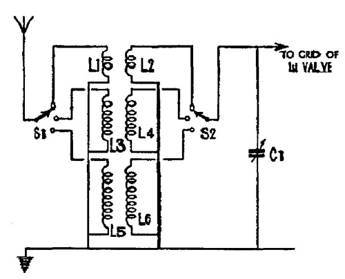
FIG. 7 The circuit of a triple wound RF transformer for short (L1/L2), medium
(L3/L4) and long (L5/L6) waves.
The results of all these various developments was that the vast majority of commercially built TRF battery receives likely to be encountered by the amateur radio mechanic fall into the three- tubes (valves) class with an s.g. or pentode as RF amplifier, a triode (sometimes a straight pentode) as detector and a pentode as the output stage. Two representative circuits are shown in Figures 9.8 and 9.9; they are entirely typical and their design points should be studied.
The first employs a straight s.g. tubes (valves) as RF amplifier, its control grid fed from the secondary of a dual RF transformer covering medium and long waves (L1/L2 and L3/L4). Note that L3 and L4 are shorted out by S1 and S2 when the set is switched to medium waves. Three different aerial input sockets are provided, Al going to the top of L1, A2 going to a tapping on it and A3 also going to the tapping but via a small capacitor (typically 100 pF). These are to suit aerials of different length and efficiency. VC1 is the first tuning capacitor.
Note that the screen grid of V1 is supplied with voltage from a separate tapping on the HT battery. Capacitor C5, typically 0.1 uF decouples the screen grid (i.e. provides a low impedance path) to chassis to obviate the possibility of instability occurring as the HT battery ages and its internal impedance rises.
The anode of V1 is supplied with HT via the primary of another dual RF transformer (L5 and L6) which couple the amplified RF signals to secondary windings L7 and L8 and thence to the grid of the detector, V2. Note that both L5 (MW) and L6 (LW) are in circuit on both bands whilst S3 shorts out L8 on MW. VC2 is the second tuning capacitor.
Typical values for C2, the grid capacitor, and R1, the grid leak, would be 100 pfd and 1 m-Ohm respectively. Any residual RF remaining after detection is by-passed from V2 anode to chassis by C3, typically again 100 pF, and prevented from reaching the primary of the inter- tubes (valves) transformer, L11, by the HF choke L10. Also connected to the anode of V2 is the reaction winding L9, which is common to both MW and LW. VC3 is the reaction capacitor and placing it at the bottom end of L9 enables its moving plates and control spindle to be connected to chassis, enhancing stability. The top end of the inter- tubes (valves) transformer secondary, L12, is connected to the control grid of V3 whilst the lower end goes to a suitable tapping on the grid bias battery. L13/L14 form the output transformer coupling the signals from V3 anode to the speech coil of the moving- coil loudspeaker. C4 is the pentode tone control capacitor, a typical value being 0.01 uF. HT for both anode and screen grid of V3 and for the anodes of V1 and V2 is obtained from another tapping on the HT battery. C5, typically 1 uF, decouples the latter to chassis.
Our next circuit ( FIG. 9) may appear superficially very similar to the first but closer inspection will reveal many differences.
The RF amplifier is now a variable-mu pentode, with input to its control grid from the dual secondary of an RF transformer (L3 for MW and L4 for LW) with S1 shorting out L4 on medium waves. There is a single primary or aerial winding common to both MW and LW and the aerial input is brought in either via C2 or the tuned circuit comprised of L1 and C1. This is an entirely typical ‘Droitwich rejector’ of the late 1930s fitted to reduce overloading in receivers installed near to that particular transmitter. It is actually, of course, an acceptor circuit able to pass any frequency but that of the Droitwich. VC1 is the first tuning capacitor.
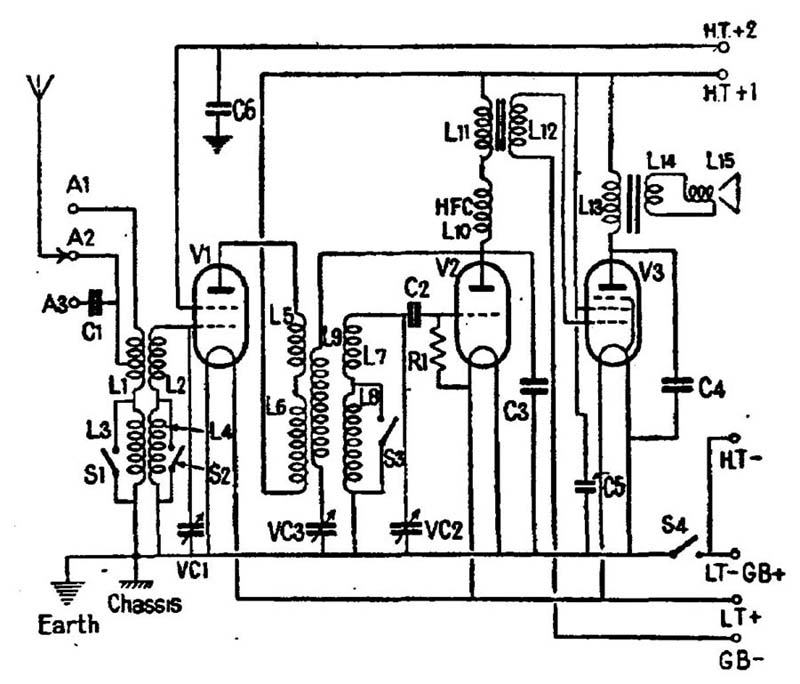
FIG. 8
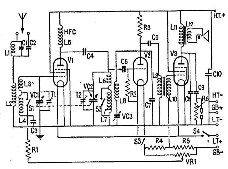
FIG. 9
Note that the bottom end of L4 does not return to chassis but goes to R1, typically 500 k-Ohm. L This in turn is connected to the slider of potentiometer VR1 which is connected between GB— and chassis. In this case the GB battery would be a 9 V type, sufficient fully to control an average battery RF pentode. C3 is a by-pass capacitor, typically 0.1 uF used to give L4 a low impedance RF path to chassis.
Choke-capacity coupling transfers the amplified RE signals at Vi anode to the control grid of V2, with L6 and L7 as grid tuning coils. S2 shorts out L7 on MW. VC2 is the second tuning capacitor and the dotted line joining it to VC1 indicates that the two are ganged or operated simultaneously by a single control knob. Note Ti shunted across VC1 and T2 across VC2. These are small trimmer capacitors of about 100 pF maximum used to cancel out small discrepancies in the tuning of the RF and detector stages as thus bring them into close alignment, the aim of this to maintain even sensitivity and selectivity throughout the tuning ranges.
C6 is the grid capacitor and R2 the grid leak for V2; their values would be much the same as in the previous circuit. Also very similar would be the value of VC3, the reaction capacitor, and C7, the RF by-pass capacitor.
Although transformer coupling is still used between V2 anode and V3 control grid, the primary winding L9 is now parallel fed by the load resistor R3 (50k—100k-Ohm and the coupling capacitor C6 (typically 0.5 uF. The bottom end of secondary winding L10 goes to the junction of R4 and R6 which together form a voltage divider across the GB battery. The values are chosen to give a bias voltage at their junction suitable for the grid of V3, a typical value being 4.5 V.
C8 (around 0.01 uF) is the fixed pentode tone control capacitor while C9 (around 0.02 uF and R6 (around 22 k-Ohm) from an extra semi-variable tone control, a plug and socket arrangement, enabling R6 to be shorted out at will to cut even more the high frequency AFs. C10 is an HT decoupler of about 1 uF capacity.
S4 is the main on/off switch, breaking the LT+ supply to the tube (valve) filaments. S1 is included and ganged with S4 to break simultaneously the path between R4 and chassis, thus avoiding a steady discharge of the GB battery when the set is out of use.
Improving the output
As regards power output, battery receivers always were subject to design constraints whereby good performance had to be balanced against economy, for HT batteries never were cheap. “The heart of many a conscientious set designer is broken when he tries to develop a battery set which will do justice to his ideals of quality of reproduction, for whilst engineering knowledge tells him that a power output of about one watt is necessary, common sense dictates that no HT battery is obtainable at a reasonable cost will supply this power. Even with a high-efficiency pentode the drain on the HT battery for the power output tubes (valves) would be about 20 milliamperes”, wrote Mr. E. Yeoman Robinson, the Chief Engineer of the Mazda Tube (valve)Laboratories in 1932. If more output power is required, regardless of battery consumption, the better alternative to using one large output tubes (valves) is to use two standard tubes (valves) in what is called a push-pull output stage. Either triodes or pentodes may be employed. The control grids are supplied with signals by a centre-tapped input transformer with the centre tap taken to GB—. For Class “A” operation. The bias voltage is selected to hold the grids at the centre point of the straight portion of the operating curve, just as with an ordinary single output valve.
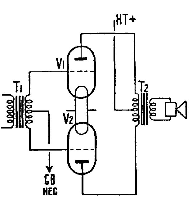
FIG. 10 Push-pull output stage using triodes for either class ‘A’ or ‘B’
operation-only the value of the grid bias voltages is altered.
One end of the primary winding of the input or driver transformer is taken to HT+ and the other to the anode of a preceding AF amplifier or driver valve. Signals amplified by this tubes (valves) appear on the secondary of the transformer in opposite phase with respect to the centre tap, that is, a positive going signal is applied to the grid of one output tubes (valves) and a negative going signal to the other. Thus the anode current of one tubes (valves) rises as the other fails and vice-versa as opposite phase inputs continue to arrive at the grids. The output is coupled to the loudspeaker by a special centre- tapped output transformer, the centre tap itself being taken to HT+ and the outer ends to the anodes. The total effective output power developed by two tubes (valves) in Class “A” push-pull is likely to rather more than double that of a single tubes (valves) of the same type. In addition the fact that the anodes are working in opposite phase cancels out certain forms of distortion so the quality of the sound is usually better than with a single valve. Yet another advantage is that the anode currents flow in opposition to one another and reduce the magnetizing effect on the soft iron core of the transformer. This in turn means that the transformer may be physically smaller that otherwise would be the case.
There is, of course, a price to be paid for higher output in the amount of current drawn from the HT battery. One attempt to ameliorate this was the Class ‘B’ push-pull stage, in which the grid bias for the output tubes (valves) is arranged to hold the anode current near to cut-off point in the absence of incoming signals. These are again supplied by a centre-tapped driver transformer but each tubes (valves) can respond only to the positive half-cycles of the input, when the grids are driven positive and the anode current increases. On the negative half-cycles the grids are driven even more negative to way past the cut-off point. In practice the power output of a Class ‘B’ stage may be quite impressive - typically 1.25 W — but the saving in HT current is not as great as might be thought. Although the no-signal current may be low it may soar to as much as 45mA with some tubes (valves) on peak positive inputs. The average would probably be around the 15mA mark, but added to this a high level of drive power is required for the grids and the preceding stage may have to employ a power triode taking around 3 mA if the full output is to be realised.
True economy combined with high output power in battery sets had to wait until the development of Quiescent Push-Pull (QPP) in the Mazda Tube (valve)Co.’s laboratories during 1932. For QPP operation two output pentodes are arranged in a similar way to that used for Class A push-pull, but with the grid bias selected to take each tubes (valves) to a very low point on its characteristic curve at which the anode current is extremely low; in the case of the entirely typical Mazda Pen220A it is about 1.8 mA. For a pair of tubes (valves) the total drain, including the screen grids is around 4 mA, giving a very significant saving in HT current under no signal conditions. When signals arrive the two tubes (valves) again operate alternately (they respond only to the positive swings) and the anode current is exactly proportional to the amplitude of the signal. Operated under these conditions the theoretical efficiency of a pentode is raised in theory by as much as 80% and in practice by about 50%. What this means in performance is well illustrated by data recorded in the Mazda Laboratories. A pair of Pen 220As were found to draw a maximum of 16 mA with a continuous high amplitude signal corresponding to transmitter modulation of around 90—100%. However, as the average modulation level of a radio stations is (or at least was in 1932) no more than 15—20% the potential saving in HT current is evident. Used as they would be in an ordinary domestic receiver, a pair of Pen 220A working with a 120V HT battery and with a grid bias of 10.6 V delivered a genuine 1.3 W to a loudspeaker for an average anode current of about 6—7 mA, a most remarkable achievement.
Initially two separate pentodes were used for QPP but quite soon the major tubes (valves) manufacturers had developed double-pentodes especially intended for QPP work. Final matching of the two sections had to be carried out in the individual receiver by adjusting the screen grid voltages according to code letters stamped on the tube (valve) envelope. The bias, too, had to be set with care. By about 1936 a new generation of QPP tubes (valves) arrived in which the need for separate screen grid voltages was eliminated and a standard type of 120V HT battery could be employed.
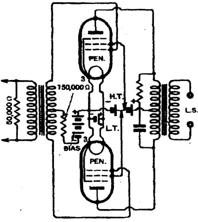
FIG. 11 The original Mazda circuit for QPP. Note the separate tappings on
the HT battery for each screen grid.
Automatic Grid Bias
It was also possible to use automatic grid bias which adjusted itself effortlessly as the HT battery ran down. The bias is obtained by inserting a resistor between the negative input from the HT battery and chassis so that a small voltage drop occurs across it as the steady HT current flows. This means that HT— is now slightly negative with respect to chassis, and this voltage can be used to provide grid bias for the tube (valve). By using two or more resistors in series and choosing their values carefully different suitable voltages may be obtained for all the various stages in a receiver. Interestingly, automatic grid bias was invented in the early 1920s but apparently a patent prevented its being used generally for a dozen or more years.