AMAZON multi-meters discounts AMAZON oscilloscope discounts
On this page: Desirable Enclosure Characteristics-Enclosure Shape Speaker Placement
-Materials-Construction Rules Finishing Your Speakers-More Box Construction
Hints Project 2: Designing and Building an Enclosure
The principles of good speaker enclosure design and construction hold for any speaker project, regardless of box type. By heeding those principles you can build with confidence and prevent long debugging procedures. If you are inclined toward novelty in your choice of furniture, let that trait be expressed in your speaker enclosures by such superficial aspects of design as external appearance. For those design features that affect the sound, stick to basics.
DESIRABLE ENCLOSURE CHARACTERISTICS
The single most desirable characteristic of a good enclosure is that it does not seriously alter the sound of the speakers installed in it. A speaker system is different from a musical instrument in one important aspect: the speaker should produce no sound of its own.
An instrument produces sound; a speaker reproduces it. If the speaker adds anything to the signal it receives, it is producing distortion. If the enclosure walls vibrate audibly, they will color the sound and weaken the true bass response by absorbing low frequency energy. A bad enclosure shape can spoil reproduction by lumping the inevitable air resonances around a narrow band of frequencies, producing a boomy system.
ENCLOSURE SHAPE
Enclosures with non-parallel walls, such as triangular boxes, have fewer problems with internal reflections. Most speaker builders as well as other audio fans choose ordinary box-like enclosures because they are easy to build and "look like speakers." To make the most of these, avoid extreme shapes. As a rule of thumb make sure that no internal dimension measures more than 3 times that of any other. But don't make them too close to each other or you will have a cube, one of the worst shapes for any but miniature boxes.
A preferred ratio of dimensions, frequently cited by acoustical engineers, is 0.62 : 1 : 1.62. This ratio, based here on its acoustical properties, is the same "golden ratio" of artists since the days of the Egyptian pyramids. Unless you have a special reason to use another ratio, this one will insure that the resonances will be spread instead of lumped. Figure 3-1 gives the right internal height, width, and depth for speaker boxes with net internal volumes ranging from 400 cubic inches (0.23 cubic foot) to 10,000 cubic inches (5.8 cubic feet). If you multiply the figures you get from the graph, you will find that the cubic volume obtained will be slightly larger than the one shown on the left margin. The extra volume of about 10 % was calculated into the graph to allow space for speakers, cleats, and other internal parts.
Here is an example. Suppose you want to build a box with a net internal volume of 4000 cubic inches (2.3 cubic feet). Follow the horizontal line from 4000 in the left margin and find where it crosses each dimension curve, then read that dimension by referring to the values given at the bottom of the graph. Here we find the 4000 line crossing the D (depth) line at 10", the W (width) line at about 16 1/2", and the L (length or height) line at 26 3/4" .
Multiplying 10 x 16.5 x 26.75 we get 4413.75 cubic inches. So the over-volume here amounts to about 414 cubic inches, probably enough to allow for the internal space occupied by the speakers and internal bracing unless you are building a reflex cabinet that includes a large tube for a port. Where large ducts are used, the volume of the duct should be estimated and added to the required cubic volume. For closed box speakers the dimensions given by Fig. 3-1 will be satisfactory.
In some cases you must choose another ratio for various reasons. One example, if you want to install a 3-way system in a compact enclosure and want to mount the 3 drivers in a vertical line, which is a desirable pattern, you may have to make the cabinet's length to width ratio greater than 1.62 in order to make room for the speakers. In such situations try to stagger the dimension so that the width and depth are not equal.
Note that the dimensions given in Fig. 3-1 are internal measurements, so you must add enough length and width to the...
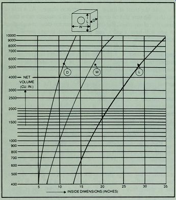
Fig. 3-1. Internal dimensions, based on the Golden Ratio, for speaker enclosures
with a net cubic volume of 400 to 10000 cubic inches. These dimensions allow
about 10% over volume.
...wall panels to account for wall thickness. For example, if you want to build an enclosure with bevel joints, such as you might use with a good grade of plywood, you would add 1 1/2" to the internal length and width to get the proper length for side, top and bottom panels.
If you add a particle board liner, as done with some of the projects in this guide, you would add enough extra length to account for a double thickness of the liner. For an enclosure with butt joints you would add 1.5 ", but only to those panels that overlap the other panels.
SPEAKER PLACEMENT
The first rule on driver placement is: put the high frequency speakers above the low frequency speakers (Fig. 3-2). If followed, this practice puts the tweeters nearer ear level, where their directional sound won't be lost, and woofers nearer the floor for good bass reinforcement.
The second rule is: put the drivers in a vertical line with little or no horizontal displacement. When speakers are mounted side by side, there will be a difference in path length from each speaker to the listener's ear, producing phase distortion. Sometimes lack of space makes side by side mounting inevitable.
The third rule is: if the vertical line of drivers is placed off center, make the second speaker board of your stereo pair a mirror image of the first. This allows you to place the speakers so that in both enclosures the drivers will be off centered inward, or outward, rather than having one enclosure with the drivers inward and the other with the drivers outward from the space between your speakers.
MATERIALS
The most commonly used speaker box material is 3/4" plywood or particle board. Panel thickness should be chosen to match enclosure size. If the box is small enough, under 1/2 cubic foot in volume, it can be made from ½” or even 3/8" material. Small panels are stiffer than large panels of the same thickness, so you
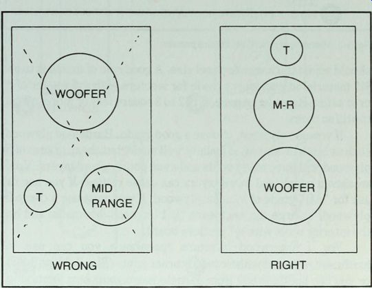
Fig. 3-2. Right and wrong speaker placement. Some designers prefer to mount
the line of speakers off center if space permits.
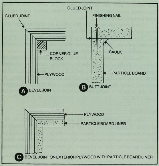
Fig. 3-3. Methods of joining enclosure panels.
GLUED JOINT; FINISHING NAIL w CORNER GLUE BLOCK PLYWOOD BEVEL JOINT; CAULK PARTICLE BOARD BUTT JOINT; PLYWOOD PARTICLE BOARD LINER BEVEL JOINT ON EXTERIOR PLYWOOD WITH PARTICLE BOARD LINER
---------------
... should adjust thickness to panel size. A good rule of thumb is to use 3/4" material in enclosures made for woofers with a diameter of 8" or greater. Brace large panels, of 2 to 3 square feet or more in area, to stiffen them.
If you use plywood, choose a good grade. Hardwood plywood, such as birch or walnut, is usually well made, but cheap grades of fir plywood will have many voids and even poorly glued layers. Voids weaken a panel, and loose layers can cause rattles. If you use fir, ask for "AB" grade of interior plywood. If you must use a cheap fir plywood, enlarge the enclosure by 1" in each dimension and line the interior walls with 0.5" particle board.
For a fine wood furniture appearance you can use W hardwood plywood with beveled corner joints (Fig. 3-3A or 3-3C), or you can build the box from particle boards with butt joints (Fig. 3-3B), then apply a wood veneer. Or you can cover the box with any kind of material you choose, from cloth to wallpaper.
Many audio fans would like to build speaker enclosures but lack power tools and feel that their homemade boxes would look amateurish. If this is your situation, you can make use of a design that permits a wrap-around grille cloth. The grille cloth will hide all matching joints, making your cabinet work look good even if it is rather crude. The basic procedure is shown in Fig. 3-4. You can build the particle board box, then add slab sides that extend beyond the box, and finally install the grille cloth. If you prefer a hard surface on the top of the enclosure rather than grille cloth, you can install boards top and bottom and wrap the grille cloth around from side to side as shown in Fig. 3-5.
Pine can be used for the exterior walls of the enclosures, but it isn't as strong as plywood and much less dense than particle board.
It is particularly useful for slab sides in the easy-to-build enclosure of Fig. 3-4. Where it is used in a more conventional way, such as in Project 8 in Section 10, the box should be lined with W particle board. Pine is attractive but must be handled carefully to prevent it from warping. One precaution to observe, don't cut out the parts until you are ready to assemble them.
--------------
BUILD SHELL
ADD SPEAKER BOARD CAULK
ADD BACK AND CAULK THROUGH WOOFER HOLE ADD FACE BOARD
ADD SLAB SIDES OF PLYWOOD OR PINE AND INSTALL GRILLE CLOTH
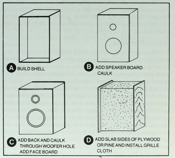
Fig. 3-4. How to construct speaker enclosures without use of power tools.
----------------------
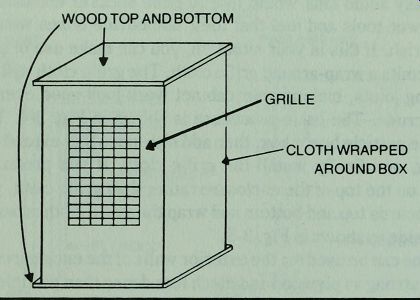
Fig. 3-5. Alternate way of hiding box with wrap around grille cloth.
Particle board is especially desirable because of its high density, lack of voids or loose layers, and its low cost. Its only disadvantage is that it dulls saws more quickly than other materials mentioned here. If possible use a separate saw, or saw blade, for cutting particle board. When buying it, choose an industrial grade.
You can identify the most satisfactory particle board by examining the particle size at the edges of the board. The best board for speaker boxes has small particles and smooth edges. Avoid the kind that is crumbly or flaky.
CONSTRUCTION RULES
There are many ways to build a satisfactory speaker enclosure. You may want to change some of the construction methods shown in the projects in this guide; just make sure you don't make significant changes in cubic volume. In building any speaker box, observe the accepted rules of construction.
•Rule 1: Make A Rattle-Free Box. The best way to avoid rattles is to do a good job of gluing the joints. Experienced carpenters use just enough glue to hold, but not enough to squeeze out onto raw wood and spoil the appearance. That technique works well with most furniture but, if overdone, can cause problems in speaker boxes. Unless the parts are cut to close tolerances, the skimpy use of glue can leave air leaks as well as rattles. To avoid problems with excess glue, cover the exterior wood near the joint with masking tape before gluing. And spread the glue thicker near the interior side of the joint. After assembling the parts, remove excess glue with a damp cloth.
If you make one panel removable, use carefully installed foam weather stripping material to seal the box and prevent rattles. Such panels will usually be held in place with wood screws, size #8 x Wa" is about right, screwed into solid wood cleats. Position the weather stripping so the screws won't catch and damage it. When installing removable panels, place the screws no farther apart than about 4 or 5 inches.
•Rule 2: Make The Box Airtight. Even the smallest gap between joints can cause air noises that mar performance. If the air leak is significant, it can unload the woofer, increasing distortion and limiting its power handling ability. To insure against leaks, caulk every joint with latex caulking compound. If you are building a box with no removable panels, you can start by assembling the sides, top, bottom and the speaker board. Caulk every inner joint (Fig. 3-6), then install the back. You can reach through the speaker holes to caulk the joints around the back.
Apply the caulking material with a gun; then, if necessary, smear it into the joint with a rounded tool. Popsicle sticks make good spreading tools.
• Rule 3: Don't Forget Damping Material. Speakers that don't have enough damping material sound loud, even at low volume. Damping material is necessary to absorb sound from the rear of the cone-sound that would otherwise be bounced around the box and reflected out through the cone. Damping material suppresses mid-range peaks, making the response curve much smoother.
If you are building a reflex system, keep the port free of damping material or any other obstructions, unless it is called for in the design.
One traditional rule of thumb is to put damping material on the interior of the back panel, one side, and either the top or bottom panel. The theory behind this advice is that one layer of damping material in each dimension will absorb rear reflections. In the real world one should aim for a margin of safety and put damping material on every interior wall except the speaker board. For final adjustment, use your ear. Add more material to any system that sounds loud at modest volume levels. Make sure the walls near the woofer are heavily covered and, if necessary, hang a curtain of material behind the woofer. If there is a single note boom, try stretching a layer of material over the back of the woofer, stapling it to the speaker board. Make sure this damping pad is stretched tightly.
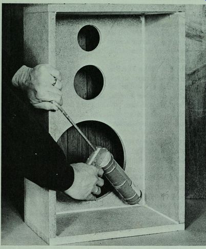
Fig. 3-6. Caulk all inner joints of speaker boxes. Project 2 shown here.
In addition to absorbing reflections, damping material can be used to increase the effective cubic volume of the box. It does this by changing the operation of the box air from adiabatic (constant heat) to isothermal (constant temperature). With isothermal operation the stuffing absorbs and gives up heat, maintaining a constant box temperature and reducing sound velocity. This shortens the wavelengths. In theory, you can add about 40 % to box volume by stuffing; in practice, about 20% is the limit. To stuff a box, cut the damping material into small pieces and loosely fill the box. Don't force enough material into the box to compress it.
What kind of damping material? Fiberglass is probably the most widely used because it is widely available and its characteristics are well known. The acoustical grade comes in packages of one square yard of material 1" thick. It is the preferred kind because it stays in place better than looser kinds. Ask for Radio Shack Cat. No. 42-1082. You can substitute other materials such as polyester batting, rug underlayment, or old rags; but beware of dense materials that would significantly change box volume.
• Rule 4: Install Drivers From Outside The Box. In earlier days the typical high fidelity speaker was bolted to the rear of the speaker board (Fig. 3-7). In some enclosures that is the only practical way to mount a driver; but, if the panel is very thick, such mounting produces a cavity at the front of the speaker that can color the sound. The sharp edge of the speaker cut-out may diffract the sound waves, producing interference which causes dips and peaks in the mid-range.
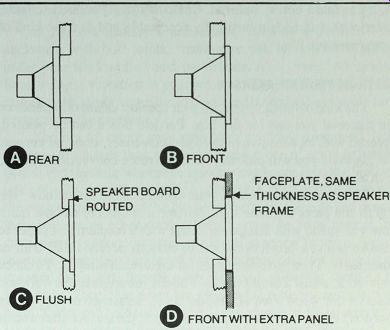
Fig. 3-7. Several methods of installing speakers. Methods C and D are the
preferred ones, A is least desirable.
---------
SPEAKER BOARD ROUTED
FLUSH FACEPLATE, SAME
THICKNESS AS SPEAKER FRAME FRONT WITH EXTRA PANEL
Front mounting solves those problems and permits a more vibration-proof box because there is no need for a removable panel.
When every panel is glued to the others, rather than held by screws, it's unlikely that rattles can develop with use.
Some speakers come with a mounting gasket on the rear of the frame; others have no rear gasket. To install a speaker with no rear gasket, set the enclosure on its back and wire the speaker. Run a bead of silicone rubber compound around the edge of the speaker cut-out and press the speaker into place. Leave the box in that position for several hours, preferably overnight, until the silicone glue sets. The silicone rubber forms a perfect gasket and glues the speaker to the board. For speaker systems with very large woofers, 15" or larger, you can install T-nuts for speaker holding bolts. Drill speaker mounting holes one size larger than the bolts you intend to use, then drive the T-nuts into the holes on the back of the speaker board before you assemble the box. For example, if you want to use 3/16" mounting bolts, you would drill W holes and drive 3/16" T-nuts into the holes at the rear of the board. With T-nuts in place, you can run a bead of silicone rubber around the cut-out, to make a gasket, but you won't have to leave the box on its back after installing the speaker.
•Rule 5: Choose An Open Grille Cloth. Don't cover super tweeters with a thick drapery material. Use a grille cloth made for the purpose, or test any cloth that you want to use by holding it up to the light. If you can see through it, it is probably a suitable choice.
A better test is to hang the cloth over your speakers and listen. If you can hear any change in the sound when the cloth goes on, try to find a better material. Obviously you should try to find a material that is both acoustically acceptable and has the kind of appearance you like.
FINISHING YOUR SPEAKERS
The kind of finish you put on your speaker cabinets depends on the material you use for the box. Particle board can be painted, covered with an adhesive-backed plastic veneer, or wood veneer.
For plywood you will probably choose a more conventional finish, such as stain and varnish.
The final appearance of your cabinets depends on how well you fit the parts together and, perhaps even more, on how much time you spend with sandpaper. Start with a medium grit paper to remove uneven projections and to smooth poorly fitted trim or other parts. Then go to fine paper for the overall sanding. To check your work, adjust a bright light at a 30 degree angle to the work and observe the wood from all angles. Small scratches or saw marks that don't show on raw wood seem to leap to the surface after a stain is applied.
One of the easiest finishes to apply is an oiled wood finish.
Stain the cabinet to the color you want, then coat it with a mixture of 3 parts linseed oil and 1 part turpentine. Make up the oil-turpentine mixture; then apply it with a rag soaked with the liquid mix. Allow it to stand for a half hour or more; then wipe it clean with a dry cloth. Sand lightly with a 360 grit wet or dry sandpaper and apply another coat. Do this until you have put 3 coats on the enclosure. Then rub it down. Repeat the process with a further coat once or twice a year for the first few years.
Another easy finish is paste shoe polish. Stain the enclosure, then add the polish for more color and a wax finish. Brown shoe polish over fruitwood stain gives a reddish, almost mahogany, color. If you want other effects, practice with multiple coats of various shades of shoe polish over stains on a piece of waste material that is identical to the wood used in the cabinet.
If you apply conventional finishes, such as varnish or lacquer, beware of incompatible combinations. The easiest way to make sure that your stains and final finishes will work well together is to buy a stain and varnish of a single brand name from a knowledge able paint dealer. For a smooth looking finish, choose a satin or dull varnish, at least for the final coat. And don't use wax or polish on any cabinet until the final coat of varnish has been applied.
MORE BOX CONSTRUCTION HINTS
If you are making a nailed box, such as a particle board enclosure with butt joints, make sure you have a solid surface under your work while you drive in nails. A concrete floor is ideal.
Even a slight vibration in your work surface while you are nailing makes tight joints virtually impossible to attain. Bent nails are a symptom of the problem.
You can fill minor gaps with latex caulking compound, but if the gaps are larger than about 0.25", use a piece of wood or particle board. Fill the hole where the speaker cord goes into the box with latex or silicone rubber caulking compound. It's a good idea to knot the cord on the inside of the box so it won't pull through and damage the speakers or other components if someone trips over it. For convenient speaker connections, install a screw terminal strip in the back by drilling two holes, for each terminal, and bringing the speaker leads out through each hole and soldering them to the terminals. Then glue down the strip to the exterior surface of the back. Tacks will hold the strip while the glue sets. Fill the terminal holes on the inside of the panel with latex caulking compound. For speaker systems with crossover networks, the crossover components and screw terminals can be installed on a piece of 0.25 " ...
----------------------
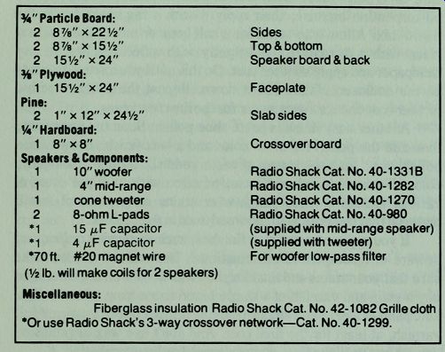
Table 3-1. Parts List for Project 2.
3/4" Particle Board:
2 87/8"x 22 1/2" Sides 2 87/8"x15 1/2" Top & bottom 2 15 1/2"x24" Speaker board & back H" Plywood:
1 15 1/2"x24"
Faceplate
Pine:
2 1"x12"x24 1/2" Slab sides W Hardboard:
1 8" x 8" Crossover board Speakers & Components:
1 10" woofer Radio Shack Cat. No. 40-1 33 1B 1/4" mid-range
Radio Shack Cat. No. 40-1282
1 cone tweeter
Radio Shack Cat. No. 40-1270
2 8-ohm L-pads Radio Shack Cat. No. 40-980
•1 15 /u.F capacitor (supplied with mid-range speaker)
•1 4 /uF capacitor (supplied with tweeter)
•70 ft. #20 magnet wire
For woofer low-pass filter (1/2 lb. will make coils for 2 speakers)
Miscellaneous: Fiberglass insulation
Radio Shack Cat. No. 42-1082
Grille cloth
•Or use Radio Shack's 3-way crossover network-Cat. No. 40-1299.
--------------------------
... hardboard which can be glued to the interior of the back. A small "window" in the back allows access to terminals and control shafts.
Check your finished enclosures for quality by rapping each panel with your knuckles. Listen for a dead, relatively high-pitched sound that means solidity. If the box sounds like a drum, the panel isn't stiff enough. A rattle tells you something is loose. If the panels are solid and stiff enough to emit a rather high-pitched sound on your rapping, you can be assured that the enclosure is well made and that the damping material will take care of the residual panel resonance.
In planning the projects in this guide several construction methods were chosen to illustrate the various ways of building a satisfactory box. You can substitute other construction procedures, but remember to plan for the recommended cubic volume.
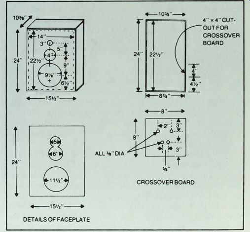
Fig. 3-8. Construction details for basic enclosure of Project 2. Pine slab
sides are not shown here.
PROJECT 2: DESIGNING AND BUILDING AN ENCLOSURE
Here we will design and build a closed box enclosure for a 3-way system using a 10" woofer, a 4" mid-range speaker, and a small cone tweeter (Table 3-1). Such a combination represents one of the most popular kinds of main speaker systems.
The woofer is an acoustic suspension model with a high compliance foam roll outer suspension. An appropriate cubic volume for this speaker is about 1.5 cubic feet-more on how to choose box volume for your speaker in the next Section; for now you'll just have to accept that figure. Going back to Fig. 3-1, and checking the horizontal line for 2500 cubic inches (1.45 cu. ft.), we get these dimensions: 8 1/2" x 14" x 23". Multiplying those values, the cubic volume will be about 2737 cubic inches, adequate to allow about 2500 cubic inches after subtracting 10% for internal space occupied by the speakers and a crossover network.
Now for some compromises. Any time there is a good reason to vary the ideal dimensions, do it. Here we can cut the internal length to 22.5 and use 24" material for the basic box, an advantage because scraps are often cut into 24" widths or lengths.
We will increase the depth to 8 7/8" to maintain approximately the same internal volume. The new internal dimensions are: 8.5" x 14" x 22 Wt giving a volume of about 2796 cubic inches.
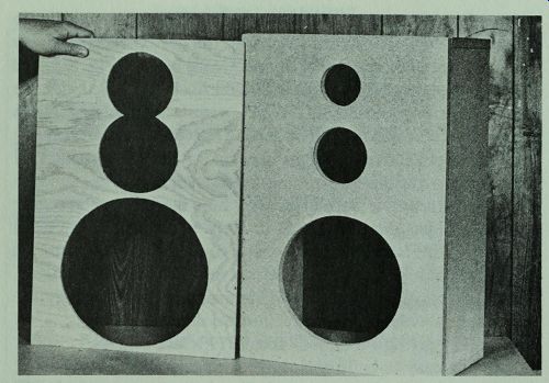
Fig. 3-9. Faceplate, left, is made like a grille board.
For an easy-to-build enclosure, with no power tools needed, we will choose the design shown in Fig. 3-4, with butt joints. The depth, 8 7/8", plus 1.5" for the speaker board and back, plus W for an external front panel to hold the grille cloth away from the front-mounted speakers just happens to come out right ( 10 3/4") so that we can use 1" x 12" pine for slab sides without ripping it. The actual width of 1" x 12" material is 11.25", which permits a 0.5” extension beyond the front board.
Cut out the parts according to the plans in Fig. 3-8, including the cut-outs in the speaker board. Begin assembly by gluing and nailing the shell, top, bottom, and sides together. Then glue and nail on the speaker board. It's a good idea to start the nails in each piece while it is supported by a concrete floor or other solid work surface, then place the piece onto the glued parts and nail it down.
Wipe the excess glue from each joint; then caulk the internal joints with latex caulking compound.
Next, install the faceplate (Fig. 3-9) on the front of the basic box with glue and small nails (Fig. 3-10). Before installing the back panel you must mount the crossover network and the L-pads on the crossover board and glue the board inside the back. For easy wiring you can use a ready-made crossover network. The new Radio Shack 3-way crossover network (Cat. No. 40-1299) offers a choice of crossover frequencies. Read the instructions that come with the crossover network and choose the connections that provide 1600 and 7000 Hz crossover points. Or you can use the general purpose crossover network diagrammed in Fig. 3-11. This homemade
crossover network makes use of the 15 uF capacitor supplied with the mid-range driver and the 4 uF capacitor supplied with the tweeter. All you have to add is a 1 mH choke. For instructions on making the choke, see Section 7.
To wire the general purpose crossover network follow this procedure:
•Prepare an 8" x 8" crossover board according to the plan in Fig. 3-8.
•Install push-button terminals (Radio Shack Cat. No. 274 621) from the smooth side of the board.
•Install L-pads (Radio Shack Cat. No. 40-980) from the rough side of the board.
•Install a 2-lug terminal strip on the rough side, as shown (Fig. 3-12).
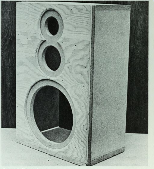
Fig. 3-10. Glue and nail faceplate to front of enclosure.
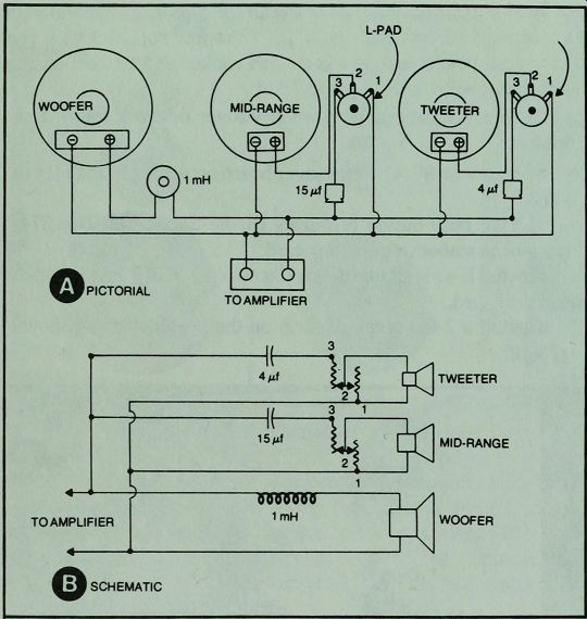
Fig. 3-11. Pictorial and schematic diagrams of the wiring circuit for Project
2.
•Run hook-up wire from lug #1 of left L-pad to lug #1 of right L-pad, then to right lug of push-button terminals or to the right lug of the 2-lug terminal strip which is connected to the right push-button lug. (Note: left or right as seen from the rough side of the board.)
•Remove the 4/uFcapacitor from the tweeter and connect one lead to the left push-button terminal, one lead to pin #3 of the left L-pad.
• Connect one lead of 15 /uF capacitor to left push-button terminal, other lead to pin #3 of right L-pad.
•Connect one lead of 1 mH coil to left lug of push-button terminal, other lead to left lug of terminal strip.
•Prepare 3 pieces of double conductor lamp cord about 18" long. Connect the woofer leads to the 2-lug terminal strip, the positive lead to the left lug. Connect the mid-range lead to terminals #1 and #2 of the right L-pad, and the tweeter leads to pins #1 and #2 of the left L-pad. In each case the positive lead goes to pin #2.
Note: The term left and right used above refer to the component positions as seen from the rough (interior) side of the crossover board. Check Figs. 3-12 and 3-13.
•Solder all connections with rosin core solder.
•Glue the crossover board over the cut-out in the rear panel, using latex caulking compound or silicone rubber sealer.
While the 1 mH coil is recommended, you can get by without it. Just make sure you use the capacitors in the mid-range and tweeter circuits.
Cover the interior of the sides, top and bottom, and back panel with a layer of fiberglass insulation. Then glue and nail down the back panel. Inspect the seam around the back for possible air leaks.
If you find any questionable points, fill the gap with caulking compound on the outside. Then work through the woofer hole to push aside the damping material and caulk the inner seam.
It's a good idea to paint the front and top panels flat black, so the speakers won't show through the grille cloth.
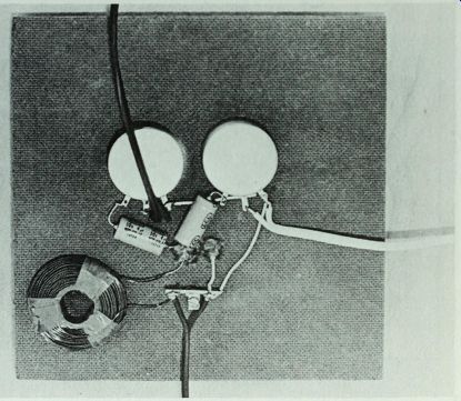
Fig. 3-12. Wired crossover board. Upper wire goes to tweeter, right one to
mid-range speaker, and lower one to woofer.
Glue and nail on the pine slab sides next (Fig. 3-14). Sand, stain, and finish them before installing the speakers. To mount the speakers, set the enclosure on its back, wire the speakers, then, working with one at a time, run a bead of silicone rubber sealant around the cut-out in the speaker board. Press the speaker down into place and twist it slightly to make a good seal. After doing all the speakers, leave the cabinet in that position overnight so the silicone rubber will set. The silicone rubber will make a perfect seal and glue the speaker to the box.
Connect the speakers to your receiver with the power turned off. Turn the volume control down before turning on the receiver, then turn it up just enough to hear the speakers clearly. Check to see that the highs come from the tweeter and the lows from the woofer. Rotate the L-pad controls to see if they are working right.
Then reduce the mid-range and tweeter level to a minimum. Bring up the mid-range level until the sound from that range blends with that of the woofer. Next adjust the tweeter until it blends. Try to get the system to sound as if only one speaker were working but at a level where you can hear all frequencies in proper balance.
When you are satisfied that everything is working right, install the grille cloth. Staple it under the bottom of the cabinet; then stretch it up and across the top, stapling it again on the back. If there are any objectionable raw edges on the grille cloth, run a thin strip of wood, or a plain narrow ribbon to match the color of the cloth, along the edges. This completes the design and construction of the project (Fig. 3-15).
If you prefer, you can use external pieces of wood for the top and bottom and wrap the grille cloth around from side to side (Fig. 3-5). A more conventional enclosure could be made from birch plywood, using bevel joints. Some listeners might consider such a hardwood enclosure more attractive, but the sound would be no better than that of the enclosure described here.
TO TWEETER TO WOOFER TO MID-RANGE SPEAKER
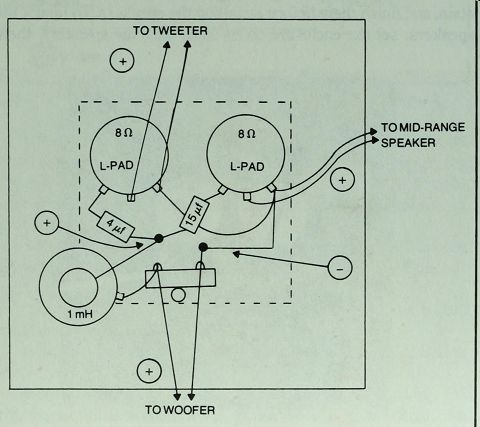
Fig. 3-13. Suggested layout of components for crossover network of Project
2.
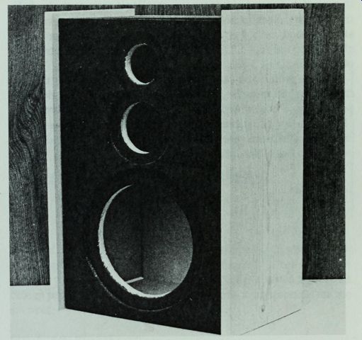
Fig. 3-14. Pine slab sides complete the enclosure.
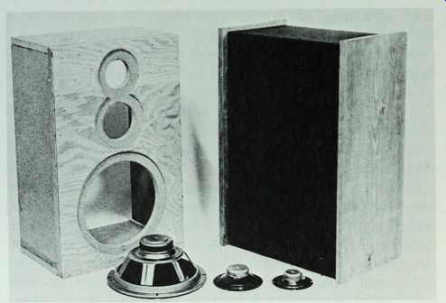
Fig. 3-15. Partially built and a finished enclosure with speaker components
used in Project.