AMAZON multi-meters discounts AMAZON oscilloscope discounts
A single cone extended range speaker has advantages, such as low cost and easy wiring. It also has some shortcomings, limited dispersion at high frequencies and somewhat greater distortion than a 2-way or 3-way system. When a single cone is expected to reproduce the entire frequency range, there is a good chance that the large cone movements necessary to produce the bass will modulate the treble. An obvious way to reduce this kind of distortion is to use one speaker for bass and another for treble, a woofer-tweeter combination. Or, for larger woofers, a mid-range driver is added for a 3-way system. This method of covering the frequency range permits us to use speakers that are specially designed to give optimum performance in the frequency bands assigned to them.
If you want to build a 2-way or a 3-way system, you must make sure that the frequencies fed to each driver are right for it. For example, it is essential that the highs go to the tweeter and, more important, that lows are blocked from it. If a small tweeter receives very much low frequency power, it will produce severe distortion, then fail. A major requirement for multi-way speakers is a properly designed crossover network.
KINDS OF CROSSOVER NETWORKS
Commercial speaker systems have a wide variety of crossover networks, from those with a single crossover component to some with extremely complicated circuits. The simpler networks sometimes perform better than the more complex ones because of more phase shift in the higher order networks. The simplest kind of crossover network is a single capacitor, called a high-pass filter.
High-Pass Filters
A capacitor offers high reactance to low frequency energy, so a capacitor in series with a tweeter serves as a high-pass filter (Fig. 7-1). A capacitor passes the highs but restricts the lows. Capacitance is measured in farads, but the values used in crossover networks are measured in microfarads (uF) or millionths of a farad. At the crossover frequency the capacitor's reactance is equal to the impedance of the tweeter. For example, if you have an 8-ohm tweeter that you want to use with a 4000 Hz crossover frequency, you would choose a capacitor that gives a reactance of 8 ohms at 4000 Hz. To find the correct value of capacitance, go to Fig. 7-2 and follow the vertical line up from 4000 Hz to the horizontal line for 8-ohm speakers. Then move diagonally to the upper left on the dashed line, and you will find that a 5 uF capacitor will provide the proper impedance at the desired crossover frequency. A 4.7 u.F capacitor, available at Radio Shack stores, will work just as well as one rated precisely at 5 uF.
When you buy a capacitor for this purpose, make sure it is a non-polarized electrolytic or a mylar type. The non-polarized electrolytic kind is available in larger values and is considerably less expensive than large mylar capacitors. Don't use polarized electrolytics for crossover duty.
If you can't find the value you need in a single capacitor, you can use more than one to obtain the desired value. Remember this rule: when capacitors are wired in parallel, their values are added.
For example, if you need a capacitance of approximately 15 uF and you have 10 uF and 4.7/u.F capacitors, you can wire one capacitor of each of these values in parallel.
Low-Pass Filters
A coil has the opposite frequency characteristic to that of a capacitor. Thus a coil in series with a woofer chokes off the high frequencies because its reactance to an alternating current increases with the frequency of the current. The more turns in a coil, the greater its reactance at any specified high frequency. One of the most popular kinds of crossover networks consists of a coil in series with the woofer and a capacitor in series with the tweeter (Fig. 7-3).
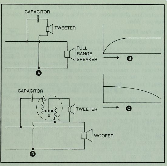
Fig. 7-1 . A single high-pass filter is the simplest kind of crossover network.
(A) A capacitor acts as a high-pass filter, and a tweeter is added to a full
range speaker to extend high frequency range. (B) Tweeter response adds high
frequency range to that of full range. (C) A full range speaker has a dropping
high frequency response. (D) Adding an L-pad in the tweeter circuit helps to
balance the output of the tweeter to that of the woofer.
That property of a coil which discriminates against highs is called inductance, and coils are often called inductors. Inductance is measured in henries, but the values that are useful in crossover networks are more conveniently measured in millihenries (mH) or thousandths of a henry. To find the correct value of inductance for a crossover network, use the chart in Fig. 7-2 as you did for capacitance, but for inductance you must follow the dashed line to the upper right. For example, if you want to make a low-pass filter for an 8-ohm speaker with the crossover point at 2000 Hz, you would find the 2K line on the chart, follow it up to the horizontal line for 8 ohms, then upward to the right to 0. 6 mH.
There are two kinds of choke coils that can be used, air core and iron core. Most commercial crossover networks use iron core chokes because they conserve wire and have lower DC resistance.
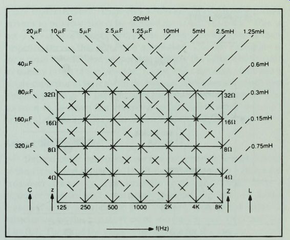
Fig. 7-2. Crossover network design chart. Approximate values of inductance
and capacitance for speakers with ratings from 4 to 32 ohms.
An air core choke needs more turns of wire for the same inductance, but if you can find some magnet wire, usually available from motor repair shops, you can make your own air core chokes.
Instructions will be given later in the Section.

Fig. 7-3. A coil in series with the woofer chokes off the high frequencies.
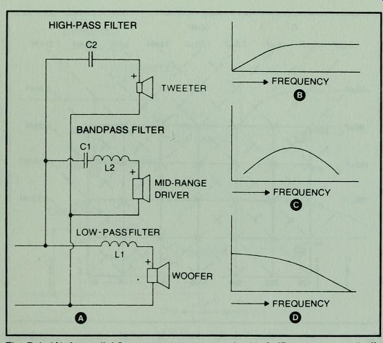
Fig.
7-4. (A) A parallel 3-way crossover network with 6 dB per octave roll-off.
Many commercial crossovers available for speaker builders use this kind of
circuit. (B) Output of tweeter. (C) Output of mid-range driver. (D) Woofer
output.
Bandpass Filters
When a capacitor is placed in series with an inductor, the combination forms a bandpass filter (Fig. 7-4). The values of the two components must be calculated so that the capacitor blocks the lows below the frequency at the lower end of the desired band width and the coil blocks the highs beyond the upper end of the desired bandwidth.
First Order Networks
Crossover networks are sometimes described by terms such as first order, second order, and so on. A first order network is one that causes the energy to a driver to be rolled off at the rate of 6 dB per octave beyond the cut-off point. This kind of network has a single component in each branch of a 2-way network (Fig. 7-3), but in a 3-way network it has 2 components in the bandpass filter for the mid-range driver.
First order networks are preferred by many engineers because they are uncomplicated, economical, and have desirable phase characteristics. Their only disadvantage is that they permit drivers to produce sound far beyond the crossover point. This is not a great shortcoming unless the drivers have peaks in their response curves that should be eliminated. The one exception is for a small tweeter that is operated down to the bottom of the safe frequency range of the tweeter. A first order network, with just a single capacitor in series with the tweeter, may permit enough low frequency energy to pass through the tweeter to damage it. The solution is to move the crossover point higher or, if that isn't practical, to use a second order network for the tweeter alone.
Second Order Networks
Second order networks have two components in each branch of the circuit and produce a 12 dB per octave roll-off beyond the crossover frequency. For example a tweeter would have a capacitor in series with it and a coil in parallel (Fig. 7-5). To design a second order network for your tweeter, look up the value of capacitance for the crossover point you want to use, then multiply it by 0.7. Then find the value of inductance for the same frequency and multiply it by 1.414. For a second order filter for an 8-ohm tweeter with the crossover point at 4000 Hz, the correct values to ...
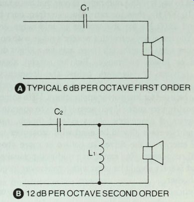
Fig. 7-5. Changing the value of C and adding a choke across a tweeter provides
a sharper cut-off at the crossover point.
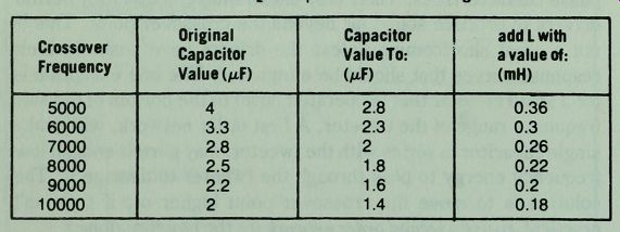
Table 7-1. Values of C2. And L, for Circuit Shown in Fig. 7-5.
... use would be 3.5 uF and 0.42 mH. These would provide the same crossover point, 4000 Hz, as a single 5ulF capacitor, but the roll-off is steeper. Table 7-1 gives some common values for second order tweeter circuits.
Many crossover networks are hybrids, containing both first order and second order sections. Most second order 3-way networks have a first order bandpass section for the mid-range.
HOW TO CHOOSE CROSSOVER FREQUENCIES TO MATCH DRIVERS
The easiest way to choose the right crossover frequency for a driver is to follow the manufacturer's recommendations. If a woofer is listed as having an effective frequency range to 2500 Hz and you want to use it with a mid-range driver that has a range from 1500 Hz to 10,000 Hz, then you can choose any frequency between 1500 Hz and 2500 Hz for the woofer to mid-range crossover frequency. You can always stretch a woofer's range with no damage to the speaker system, although there may be a slight dip in the upper bass or lower mid-range. But be careful about using mid-range drivers or tweeters below the frequency range suggested by the manufacturer. It can be done safely only if the system is to be used for low power applications. With some drivers the sound quality may suffer if you permit them to operate through their frequency of resonance. As a rule of thumb, mid-range speakers and tweeters should be used with crossover networks that cut off energy to the driver an octave or more above their fundamental resonance. For example a mid-range speaker with a resonance at 500 Hz should be used with a crossover frequency of 1000 Hz or higher.
Theoretically a woofer should be used to cover only that frequency range below where the wavelength of the sound is equal to the effective cone diameter of the woofer. This would be a rigid rule only if speaker cones were rigid pistons. They obviously are not, but here are the theoretical upper limits: 8" woofer, 1500 to 2000 Hz; 10", 1500 Hz; 12", 1200 Hz; and 15", 1000 Hz.
COMMERCIAL CROSSOVER NETWORKS
A minimal crossover network, such as a high-pass filter, is useful for many speaker systems, but a full crossover network is more desirable. A large woofer, such as a 12" model, usually gives better performance if the crossover frequency is lower than that provided by a typical general purpose network. This problem, and several others, can be solved with a crossover network that offers a choice of crossover frequencies.
For example, Radio Shack's 3-way crossover network, Cat. No. 40-1299, has tapped chokes and multiple capacitors so that the user can choose the correct tap or the right capacitor to match the requirements of his speakers. If this sounds complicated, it isn't at all. You simply wire the output of your receiver to the two lugs marked "IN," one terminal of your woofer to the common, or negative, lug on the crossover network, and the positive terminal of the woofer to either of the lugs marked 800 Hz or 1600 Hz, as desired. If you choose 800 Hz for the woofer, a logical choice for a 12" speaker, then you would wire the mid-range speaker to the 800 Hz to 5000 Hz band and the tweeter to the 5000 Hz crossover. For a smaller woofer or a mid-range speaker with a more limited low end response, you would choose the 1600 Hz tap for the woofer, the 1600 Hz to 7000 Hz band for the mid-range speaker, and the 7000 Hz crossover point for the tweeter. There are 3 wiring lugs for each driver, a common lug and a choice of the other 2 lugs to select the desired crossover frequency. This makes the crossover network both versatile and easy to use. It is a suitable choice for any of the 3-way projects in this guide. Choose the 1600 Hz and 7000 Hz crossover frequencies. But make sure you remove any capacitors from mid-range drivers or tweeters before connecting them to this crossover network. Failure to do that would put two capacitors in series, decreasing the value of capacitance and in creasing the crossover frequency.
Radio Shack's 2-way crossover network, Cat. No. 40-1296, also has a tapped choke and multiple capacitors. For this unit the crossover frequencies are 2000 Hz, 2500 Hz, or 4000 Hz. With a choice of 3 crossover frequencies there are 4 connecting lugs for each driver, a common lug and a choice of 3 lugs for the other speaker terminal (Fig. 7-6).

Fig. 7-6. Two variable frequency crossover networks. Tapped chokes and multiple
capacitors permit choice of crossover frequencies for 3-way network, above,
or 2-way network, below.
EXPERIMENTS WITH MULTI-TAPPED CROSSOVER NETWORKS
The crossover networks described above are designed to be used in a straightforward manner, that is by wiring the woofer and the tweeter or the woofer and the mid-range speaker to share the same crossover frequency. But they don't have to be used in a rigid manner. Most speakers, regardless of quality or price, convert electrical energy to sound more efficiently in the mid-range than at other frequencies. The ear, also, is more efficient at converting sound energy to nerve impulses to the brain at the middle frequencies, particularly when the sound is reproduced at low volume levels. Because of these peculiarities of speakers and the ear, it is sometimes better to wire a woofer to the 800 Hz tap on the crossover network and the mid-range speaker to the 1600 Hz tap.
Or, in the 2-way network, choose the 2000 Hz tap for the woofer and the 2500 Hz tap for the tweeter. If this seems like heresy, remember that crossover networks don't act like a stone wall.
Instead of chopping off the response beyond the crossover frequencies, they produce gradual attenuation. Sometimes you can change a good speaker system to a great speaker system by just this kind of experimentation. It's one of the advantages of building your own speakers.
Here is another unusual hook-up. Suppose you want to use Radio Shack's new mid-range tweeter in a 2-way system with a 10" or 12" woofer. This mid-range tweeter, Cat. No. 40-1299, can be used down to 700 Hz, so an 800 Hz crossover would be a good choice. You can convert the 3-way crossover network into an 800 Hz 2-way network by running a wire from the positive "IN" terminal to the closest lead on the 24 uF capacitor. This by-passes the small coil which limits high frequency response when used in series with a mid-range speaker.
A HOMEMADE CROSSOVER NETWORK
Many tweeters and mid-range speakers are marketed with a suitable crossover capacitor included with the driver. By adding a single coil you can make a simple 3-way crossover network that consists of a low-pass filter for the woofer and high-pass filters for the other drivers.
The typical value of the capacitor supplied with mid-range drivers is 15 uF, and for tweeters, 4 uF. These values give crossover frequencies of about 1300 Hz for the mid-range speaker and 5000 Hz for the tweeter. With most woofers you can use the high-pass filters alone and get satisfactory performance, but a 1 mH choke in series with the woofer conserves power and avoids undue overlapping of woofer and mid-range output in the mid-range. You can make such a coil with about 69 feet of #20 gauge magnet wire and a suitable form (Fig. 7-7 and Table 7-2). This crossover network was used in several of the projects in this guide.
HOW TO MAKE A CHOKE COIL
If you want to make your own coils, get some magnet wire from a motor repair shop, then make some forms and wind the coils by hand or with an electric drill. You must first find the value of inductance that you need from Fig. 7-2. Then go to Table 7-2 for coil dimensions and proper wire gauge. Or, if the inductance you need is not listed in Table 7-2, you can use the graphs in Appendix C.
When you have the correct dimensions, make a coil form. For a permanent form you can use a piece of wood dowel of the right diameter for the core and pieces of hardboard for the sides. Glue the sides to the core. Don't use iron screws, nails, or any other iron parts in the form because they would increase the inductance unpredictably by changing the coil from an air core, or no iron, to an iron core choke.
A temporary form is one that you can use to wind the coil, then take apart to remove the sides and use them for another form. The difference is that you make up fewer sides, but you must be careful to tape the coil so it will hold its shape. The core should be hollow in a temporary form so you can leave the wire on the core and tape ...
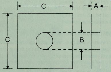
Fig. 7-7. Coil form dimensions. To find correct dimensions, refer to corresponding
letters and figures in Table 7-2.
...the coil radially, running the tape through the core and out around the outside of the coil. Pieces of plastic pipe or plastic pill bottles make good cores for temporary forms.
To prepare the form, cut out the sides and drill a small exit hole just outside the position to be occupied by the core. Then glue the form, or bolt it together. If you are planning to wind the coil with an electric drill, you will want to use a 0.25" bolt through the core regardless of whether the form is a permanent one or temporary. The bolt can be used as a clamp to hold the sides of a ...
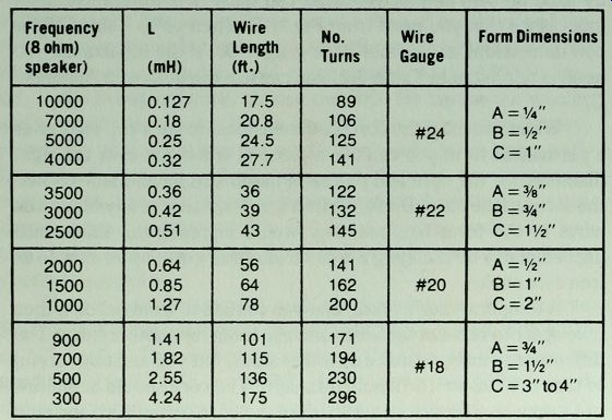
Table 7-2. Wire And Form Data for Some Frequently Used Coils for Crossover
Networks. For Coil Form Symbols, Refer to Fig. 7-7.
... permanent form until the glue sets. The bolt should be long enough to reach through the form far enough to hold washers on each side, two nuts, and an extra half inch or so to fit into the drill chuck. Two nuts are needed so one can be jammed against the other to prevent the form nut from unscrewing as you wind the coil. Don't forget that you must remove all iron from the coil before using it.
Coil specifications usually list the number of turns to make a coil with the correct inductance. Tests on many coils suggest that it is easier and more reliable to measure the length of wire. Make sure the coil dimensions and the gauge of wire is right.
To wind the coil, thread a few inches of wire through the center exit hole, from inside to outside. Note that you should add enough to the specified wire length to include this extra wire plus one at the outside of the coil. Begin winding, making sure that the first loop is placed tightly against the side of the form with the exit hole. Try to make each turn lie flat against the previous one. If you stop winding for any reason, wrap the part of the coil already wound with plastic tape to hold the wire in place until you start winding again.
When you have completed the winding, tape the coil around the exposed surface of copper wire to hold the turns tightly in place. If you are using a temporary form, remove the nuts and pull off the coil sides. Tape the coil by winding the tape through the hole in the "doughnut" and over the outer circumference.
Don't be intimidated by the coil winding process. If you are even reasonably careful in following specifications, the coil winding will be successful. Even a scramble wound air core coil will perform well unless the scrambling is extremely sloppy.
L-PADS
Tweeters and mid-range drivers are usually more efficient than large woofers, so there must be some method of controlling the sound level of these smaller speakers. Ordinary fixed resistors can be used to balance the sound of the various drivers in a speaker system, but the value of each resistor would have to be carefully chosen. Another problem with fixed resistors; you can't change the level of a driver to compensate for the acoustic conditions in your room. And, unless consideration is given to keeping the proper impedance for the crossover network, fixed resistors can cause a shift in the crossover frequencies.
These objections can be overcome by using an L-pad. An L-pad adjusts the sound level of the driver it controls much like a volume control, but it maintains a constant impedance for the crossover network and amplifier. It does this by varying a series resistance inversely with a parallel resistance (Fig. 7-1). Since almost all high fidelity speakers have a rated impedance of 8 ohms, most L-pads present a load of 8 ohms.
Choose your L-pad to match the power and crossover frequencies of your system. The power level at high frequencies is always much reduced from those of the mid-range, so you can use an L-pad designed for lower power handling in most tweeter circuits or for systems to be operated at low sound levels.
While some systems work perfectly well with no level controls on any of the drivers, most systems can be improved by adding L-pads to mid-range and high frequency speakers. In fact, one of the real advantages of a 3-way system over a 2-way system is that you have better control over the sound level at various frequency bands.
Use great care in adjusting the controls on your mid-range or tweeter drivers. The best way is to begin by turning the levels of each all the way down. Then bring up the mid-range level until it balances and blends with that of the woofer. Do the same with the tweeter control. Try to make the system sound as much as possible like a single speaker.
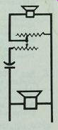
CONTOUR NETWORKS
In addition to the standard crossover networks audio engineers sometimes make use of special circuits to gain more control over a speaker system's response. A network that shapes the speaker's response curve is called a contour network. It is typical of many full range speakers to be most efficient in the band where the human ear is most sensitive, in the mid-range. Many listeners prefer this band to be slightly depressed. With a 3-way system and an L-pad, you can often achieve the desired effect by turning down the volume on the mid-range, but what do you do for a single-cone speaker? The answer is the contour network.
When a choke and a capacitor are wired in parallel, they form a circuit that is resonant at the frequency where the inductive reactance equals the capacitive reactance. At this frequency the current in the choke is equal to that in the capacitor but out of phase with it. If the circuit were composed of a pure capacitance and a pure inductance in parallel, no current would circulate in other parts of the circuit at the frequency of resonance, and the circuit's impedance at that frequency would be infinite. The capacitor and choke would form an isolated tank circuit in which a series current would flow back and forth. Note that this current appears only in the tank circuit at resonance, not in the line outside the tank.
If you wanted to eliminate sound at a certain frequency, you could use such a tank circuit, but with real components it wouldn't be perfect. A choke, for example, always includes some resistance in addition to its inductance. For a practical circuit, a third component should be added: a resistor. When a parallel resistance is wired into the tank circuit (Fig. 7-8) the resistor carries some current through regardless of frequency. If the value of resistance is several times the reactance of the other components at the frequency of resonance, the resistor will make little difference to the current flow in the circuit. But if it is about the same or lower in resistance, it will broaden the frequency response of the filter.
To design a contour network, imagine that you are designing a 2-way crossover network for speakers that have twice the impedance of your speaker. The most likely frequencies are 1000 to 2000 Hz. For example, suppose you want to make a filter for an 8-ohm speaker, centered at 2000 Hz. Using Fig. 7-2, we move up the 2K line to the horizontal line for 16-ohm speakers. From that point we find that the capacitor should be 5 uF and the choke, 1.25 mH. We would wire these components in parallel, then parallel them with a 16-ohm resistor. To get more depression of the frequencies around 2000 Hz, we would try a larger resistor; for a broader, shallower-acting filter, a smaller resistor.
One precaution about using such a filter; if you try the filter by shorting around it, to remove it from the circuit, the increase in loudness without the filter may sway your judgment against it.
Most people will prefer the louder of any two speakers. If you must test the filter, try to adjust the volume control simultaneously to make up for the loss in sound level.
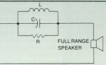
Fig. 7-8. A contour network.
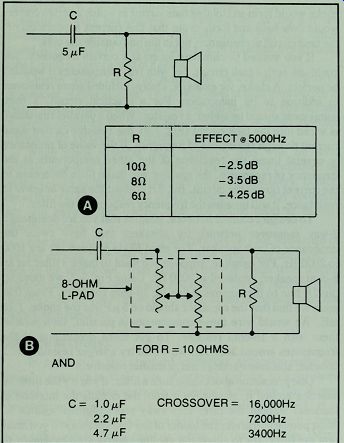
Fig. 7-9. Low end roll-off circuits for piezoelectric tweeters.
CROSSOVER NETWORKS AND PIEZOELECTRIC TWEETERS
One of the great advantages of piezoelectric tweeters is that they can be wired into a speaker system without a crossover network. The impedance of these tweeters is so high at low frequencies that the tweeter is effectively out of the circuit.
Because of this feature piezoelectric tweeters can be wired into any speaker system by hooking them directly to the amplifier, bypassing any crossover network components.
If you want to limit the lower response limit of these tweeters, you can add a capacitor and resistor for a low end roll-off at 3 dB per octave (Fig. 7-9). To put a variable control on the tweeter, you can use the other circuit in Fig. 7-9. In each of these circuits the resistor and capacitor form a network that controls the roll-off point. This permits you to use the piezoelectric tweeter purely as a super tweeter, if desired.
PROJECT 9: THREE-WAY SYSTEM WITH 12" WOOFER
This system uses the same enclosure volume, as well as the same mid-range driver and leaf tweeter, as Project 5 (Fig. 7-10 and Table 7-3). The 12" woofer here costs a bit more, but your choice between the two projects is more likely to be made on the basis of ported versus closed box than on cost. If you like your music super loud, choose this one. The closed box and the larger woofer give a higher safety margin.
Construction
Make the woofer cut-out as shown in Fig. 7-11. That and the absence of a port are the only differences in this enclosure from the one described in Project 5. You can build the box from plywood with beveled or dadoed joints, as shown, or choose cheaper particle board and use butt joints. Install cleats to hold the speaker board and back panel, and put glue blocks inside each corner joint to improve rigidity. Caulk all joints. Add a brace to the back, installed as described for Project 5.
Another view of Project 9 is shown in Fig. 8-1. There you can see the treatment given the plywood sides, a finish that some people like. If you want that much grain, burn the enclosure with a propane torch before varnishing or oiling it. A slight scorching raises the contrast of the wood grain and can make minor flaws less obvious. If you try this, first practice with a piece of waste material.
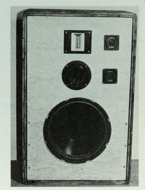
Fig. 7-10. The
12" woofer gives a full bass response. System resonance occurs at 45 Hz.
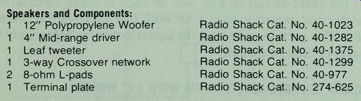
Table 7-3. Parts List for Project 9.
------------
Speakers and Components:
1, 12" Polypropylene Woofer Radio Shack Cat. No. 40-1023
1, 4" Mid-range driver Radio Shack Cat. No. 40-1282
1, Leaf tweeter Radio Shack Cat. No. 40-1375
1, 3-way Crossover network Radio Shack Cat. No. 40-1299
2, 8-ohm L-pads Radio Shack Cat. No. 40-977
1, Terminal plate Radio Shack Cat. No. 274-625
-------------------------
Make sure your work place is free of combustibles. After burning the walls you can follow with your usual finishing techniques.
As in Project 5, the crossover network goes behind the speaker board near the mid-range driver and tweeter. Remember to install a 1" layer of fiberglass on the walls and back.
Conclusion
If you compare the three closed box projects of greatly different sizes, Projects 3, 4, and 9, you will find that the smallest system has the lowest Q and the largest system has the highest Q.
There is a valid reason for this divergence. Small systems have higher frequencies of resonance, so the Q should be low to prevent peaking within the range of the human voice. For Project 9 the final frequency of resonance is 45 Hz. At such a low frequency the Q of 1.7 is hardly noticeable.
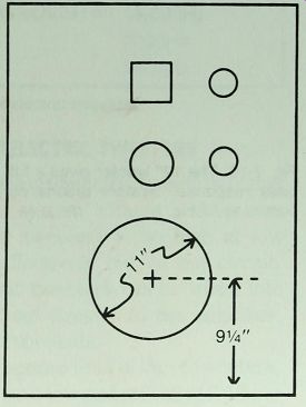
Fig. 7-11 . Speaker board for Project 9. Except for location and diameter of
woofer cut-out, all enclosure dimensions are identical to those of Project 5.
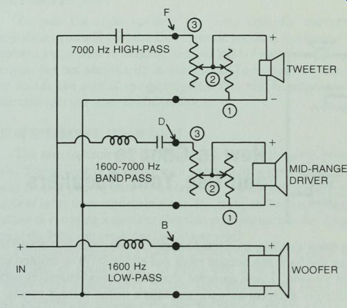
Fig. 7-12. Wiring diagram for Projects 5 and 9. Letters B, D, and F refer
to solder lugs on 3-way crossover network, Radio Shack Model No. 40-1299. Numbers
1, 2, and 3 refer to connection points on L-pads.
Rock music fans sometimes favor even a higher Q at the risk of unnatural bass. Reducing the box volume to about 2 cubic feet will raise the Q of this woofer to 2 or higher. But-double jeopardy-it will also put the system resonance above 50 Hz. Unless you are sure about what kind of bass freak you are, stick with the design shown here.
A small speaker stand that elevates the cabinet a few inches and tilts it back several degrees will provide a smoother bass response and better treble distribution.
Next: How to Choose and Use Your Speakers