AMAZON multi-meters discounts AMAZON oscilloscope discounts
Audio fans occasionally try musical instrument speakers in their stereo systems just because they happen to be available. And, worse luck, musicians occasionally press high fidelity speakers into use. The outcome of such improvisations is usually disappointment for the audio fan and a blown speaker for the musician.
The first rule of thumb involving high fidelity vs. musical instrument speakers is: they are not interchangeable. The same rule holds for PA speakers.
CHARACTERISTICS OF MUSICAL INSTRUMENT SPEAKERS
A musical instrument speaker must be durable and reliable. It must be able to take rough handling, as well as high power, without failing. Because of this requirement, musical instrument speakers have much stiffer suspensions than high fidelity speakers. While a stiff suspension restricts the cone movement and limits the extreme low frequency range, it doesn't significantly affect a musical instrument speaker's useful range. Such speakers aren't required to reproduce the sound of the lowest note of a huge pipe organ or similar instrument.
In addition to stiff suspensions, musical instrument speakers have reinforced cones, heat-proofed voice coils, and other features to prevent damage or burn-out. For still higher protection, these speakers are often used in pairs, or in groups of four, to handle more power.
PUBLIC ADDRESS SPEAKERS
The most important requirement for a public address speaker is that it can project the human voice with clarity, even in rooms with bad acoustic conditions, such as one with excessive reverberation. Extreme bass range is even less important for PA speakers than for musical instrument speakers. Deep bass response re quires large speakers and the availability of more power. Another reason to limit bass response, low frequency dispersion is harder to control than that of the higher frequencies, and uncontrolled dispersion increases feedback.
The cue to good PA performance in a highly reverberant room is, again, controlled dispersion. One way to gain such control is to install column speakers, with 4 to 6 drivers in each column. A vertical column gives good horizontal dispersion but limited vertical dispersion. In a typical auditorium, with the speakers installed near the level of a stage or floor, vertical dispersion wastes sound energy by bouncing it off the floor and ceiling. Even worse, this reflected energy reaches the audience after a slight delay, reducing clarity. So PA columns are usually installed in a vertical position to limit vertical dispersion. In some narrow rooms, where the audience is compressed into a long rectangle with the speaker at one end, better audience coverage can be obtained by using the column in the ceiling, placed at right angles to the crowd pattern. The rule in PA work is: try everything.
AMPLIFIER-SPEAKER COMPATIBILITY
While almost all stereo amplifiers are solid state, many musical instrument amplifiers and PA amplifiers in use today are vacuum tube models. The rules for hooking up speakers to the two kinds of amplifiers are different. Here they are:
•Tube Amplifier. Speaker impedance should be equal or lower than that specified at amplifier output tap or jack. Never operate amplifier without a load.
•Transistor Amplifier. Speaker impedance should be equal or higher than that specified at amplifier output tap or jack.
Never operate amplifier with a low impedance or shorted load.
Typical tube amplifiers will have several taps, or jacks, labeled 4, 8, and 16 ohms. For maximum efficiency the speaker system should be hooked to the output jack with the same impedance rating as the speaker. Some guitar players prefer to hook a 4-ohm speaker to an 8-ohm tap or an 8-ohm speaker to a 16-ohm tap because tube amplifiers seem to go into overload more smoothly when matched to a speaker of lower-than-normal impedance. When the mis-match occurs in the other direction, with a ...
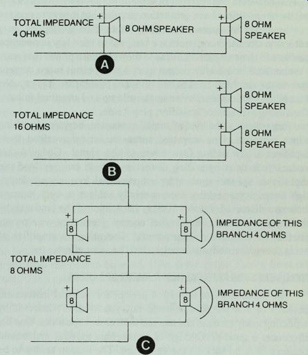
Fig. 6-1 . How parallel and series wiring hook-ups affect impedance. (A) Parallel
connection. (B) Series connection. (C) A parallel-series connection.
... speaker of higher-than-normal impedance, overload is rougher, and if the load is infinite, such as happens with a broken speaker lead, the output tubes are usually blown.
Transistor amplifiers are rated for a minimum impedance load, and this rating must be observed. For example, if your transistor amplifier specifies a 4-ohm load, don't wire more than one 4-ohm speaker system to it unless they are wired in series (Fig. 6-1). If the amplifier has an 8-ohm tap, you would connect the series-wired speakers to that tap. If you have an amplifier with one tap, for an 8-ohm speaker, and you have two 8-ohm speakers that you want to use, you would wire them in series, making their total impedance 16 ohms. Such a mis-match would cause some reduction in power, but it would be safer for the amplifier because the higher impedance would limit current flow in the output transistors. Some transistor amplifiers have protection circuits, but it pays to protect your amplifier by correct matching rather than to depend on a protection circuit. Some users are tempted to wire low impedance speakers to their amplifiers because they get more power that way.
A 2-ohm load in a 4-ohm output circuit will permit more current flow, so the amplifier tries to deliver more power than it is capable of handling without excessive heat build-up and eventual failure.
When using a transistor amplifier, play it safe.
Regardless of the kind of amplifier you use, beware of pushing it into overload. One way that some musicians overload their amplifiers is by adding fuzz tones to the signal. Gadgets that produce fuzz do it by adding distortion, which can overload the amplifier or speaker system by an unnatural frequency balance.
High frequency speakers are especially subject to such damage because a distorted signal will carry harmonics of the fundamental which have no relation to the normal frequency vs. power distribution of musical instruments. Operating an amplifier at levels above its rated power output has the same effect.
ENCLOSURES FOR MUSICAL INSTRUMENT SPEAKERS
The same laws of acoustics prevail for musical instrument speakers as for stereo speakers, but you wouldn't know it by inspecting many commercial musical instrument speakers. One big difference: a good percentage of commercial musical instrument speakers have no back on the enclosure. The reason seems to be the personal preference of some musicians for the kind of sound produced by an open box. One advantage of the speaker in the open box, a more pronounced bass response than is possible from the same speaker in a closed box of similar size. This gain in low frequency efficiency is obtained at the expense of power handling ability. If you put a speaker in an open box, you should limit the power to it to about half its rms rating. Open back speakers have one big disadvantage; when used with groups which include vocalists, or other performers with microphones, an open back speaker is more likely to cause feedback problems regardless of placement or orientation.
Plywood or particle board may be used in musical instrument or PA speaker enclosures. The typical thickness used in commercial enclosures is 0.75", although 0.5” material is often used in small systems. The enclosure can be painted, but for a more professional appearance get some cloth-backed vinyl and glue it on the exterior. Make sure the piece of vinyl is long enough to wrap around the enclosure from the bottom, up one side, across the top, down the other side, and under the bottom again. By using a continuous piece in this way there will be just one seam on the enclosure, under the bottom where it won't show. For protection and ease of handling, install metal corners and carrying handles. It's a good idea to mount large furniture glides under the box, or, for easy moving, heavy-duty casters. Such items can be found at most hardware stores.
While metal corners will protect the finish or veneer of your musical instrument enclosure, the speakers also need more protection than the typical stereo speaker. One way is to install hardware cloth, a heavy wire mesh, in front of each large cone.
Such hardware cloth can be stapled to the rear of the speaker board, behind the speaker cut-out, before bolting the speaker in the box.
Musical instrument speakers should be bolted to the speaker board. For easy bolting, mount T-nuts on the front of the speaker board at each mounting hole. Use the speaker as a pattern to locate the mounting holes, then drill the mounting holes using a bit a size larger than the bolt to be used; then drive in the T-nuts from the front. Use a split lock washer under the head of each mounting bolt.
This kind of installation permits quick removal of the speaker without disturbing the grille cloth. When installing speakers with bolts, be careful not to overtighten the bolts. It is possible to warp the speaker, which will produce a rubbing voice coil.
Another way to protect musical instrument speakers while traveling is to short the voice coils. One easy way to do this is to keep a shorted plug handy for each enclosure. When you are ready to transport the speaker, disconnect it from the amplifier and insert the shorted plug into the jack on the back of the enclosure. When the voice coils are shorted, any cone movement must be done against the magnetic field, so such movement will be reduced.
If you travel with a group that is especially rough on speakers and other equipment, you can install plywood panels over the front of your speakers while they are not in use. Such a panel can be bolted to the speaker board via T-nuts mounted on the back of the speaker board. Don't forget to replace the bolts after removing the panel or there will be air leaks that might cause unmusical noise.
MONITOR SPEAKERS
After the first concert at a new small auditorium, some of the musicians complained that they couldn't hear the others playing. A musical instrument salesman told them the sound system didn't have enough power. I heard his recommendation of more power and knew it was wrong, so I checked with the musicians and found that the people at the rear of the stage couldn't hear because there were no monitors in the system. A small monitor solved the problem and proved that the power output was adequate.
Most musicians know the importance of a good monitor, but many speakers used as such are poorly suited for the purpose.
Because a monitor speaker must face the performers, it often adds to the problem of feedback. The more vocalists or other performers with open microphones, the worse the problem. Careful placement of the monitor speaker can reduce feedback, but the monitor should be designed to cause a minimum of problems anyway.
There are two ways to design a monitor speaker for minimum feedback. These are accomplished by limiting the monitor's performance in two aspects: its direction of sound projection or its frequency response. If you are using a separate amplifier or channel for the monitor speaker, the frequency response can be controlled at the amplifier. By reducing bass range and level, feedback problems can be controlled. But direction of projection must be built into the speaker enclosure.
In planning a monitor system, you should also consider the ...
DIRECTION OF MAXIMUM PICKUP; UNIDIRECTIONAL
[microphone]
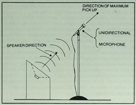
Fig. 6-2. One way to build a monitor speaker so that feedback problems are reduced.
... kind of microphones you are using. Unidirectional mikes, such as Radio Shack Cat. Nos. 33-992 or 33-984, should be employed. The ideal monitor speaker will be designed so that its sound is aimed at the back of the microphone, where it is least susceptible to pick-up (Fig. 6-2).
Another solution to the monitor problem, especially useful where a monitor is needed for a single performer, is to install one or two small speakers in a mini-enclosure and mount the enclosure on a tripod or music stand close to the performer. An L-pad control on the monitor will permit the performer to adjust its volume so that he can hear the other performers through the monitor without blasting his ears or causing feedback.
PROJECT 8: A MUSICAL INSTRUMENT SPEAKER
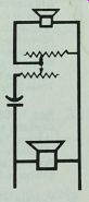
The technique used in finishing a musical instrument speaker is different from that with a typical stereo speaker, but with a bit of patience you can produce a professional looking system. For this project, a 15" musical instrument speaker and three piezoelectric super horns are required (Fig. 6-3). The super horns are installed on angled baffles to give good dispersion at high frequencies.
Except for that feature, the cabinet work is typical of many other speaker systems and requires no special procedure.
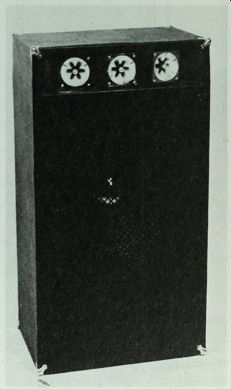
Fig. 6-3. Musical instrument speaker with an expanded aluminum grille to protect
the 15" speaker in the lower compartment.
Construction
Cut out the parts according to the plans shown in Fig. 6-4 and Table 6-1. All angled cuts, such as those made on the outside tweeter boards and the cleats behind them, should be made at 15°.
In assembling the enclosure, glue every joint except when installing the back. The back should be installed with screws so it can be removed to service the large speaker if necessary.
Start assembly by gluing and nailing the bottom to the sides.
Then glue and nail in the partition between the woofer and the tweeter compartments. Install cleats in the woofer compartment, setting them in 0.75" at the rear and 1.25 " at the front. Next, prepare the woofer board. Make the woofer cut-out in the board and then set ...
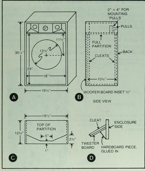
Fig. 6-4. Enclosure plans for Project 8. The lines on the partition (C) represent
the boundary between the cleats and the tweeter boards.
Table 6-1. Parts List for Project 8.
-----------------------
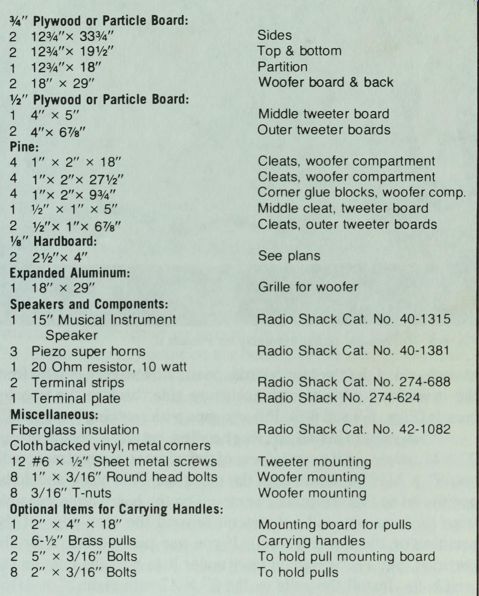
0.75" Plywood or Particle Board:
2 12 3/4" x 33 3/4" Sides
2 12 3/4" x 19 1/2" Top & bottom
1 12 " X 18"
Partition 2 18" x 29"
Woofer board & back
1/2" Plywood or Particle Board:
1 4" x 5" Middle tweeter board
2 4"x 6 7/8" Outer tweeter boards
Pine:
4 1" x 2" x 18"
Cleats, woofer compartment 4 1"x2"x 27 1/2"
Cleats, woofer compartment 4 1"x 2"x 9.75"
Corner glue blocks, woofer comp.
1 1/2" x 1" x 5" Middle cleat, tweeter board 2 1/2"x 1"x 6 7/8"
Cleats, outer tweeter boards
1/8" Hardboard:
2 2 1/2"x 4" See plans Expanded Aluminum:
1 18" x 29" Grille for woofer Speakers and Components:
1 15" Musical Instrument Radio Shack Cat No 40-1315
Speaker 3 Piezo super horns
Radio Shack Cat No 40-1381
1 20 Ohm resistor, 10 watt 2
Terminal strips Radio Shack Cat No. 274-688 1
Terminal plate Radio Shack No 274-624
Miscellaneous:
Fiberglass insulation Radio Shack Cat No 42-1082
Cloth backed vinyl, metal corners 12 #6 x 1/2"
Sheet metal screws
Tweeter mounting 8 1" x 3/16"
Round head bolts
Woofer mounting 8 3/16"T-nuts
Woofer mounting
Optional
Items for Carrying Handles:
1 2" x 4" x 18" Mounting board for pulls 2 6-1/2"
Brass pulls
Carrying handles 2 5" x 3/16"
Bolts To hold pull mounting board 8 2" x 3/16"
Bolts To hold pulls
-------------------------
... the woofer over the cut-out and mark positions for the woofer bolts.
Drill 0.25" holes at each bolt position. Then drive 3/16" T-nuts into the holes at the front of the board. Install the board in the cabinet with glue and screws or nails.
Next, install cleats on the top of the partition, located to receive the tweeter boards. Note that the cleat for the center tweeter board is set back 1" from the front edge of the partition. A center line, drawn from front to back on the partition board, helps to center the cleat and the center tweeter board (Fig. 6-5).
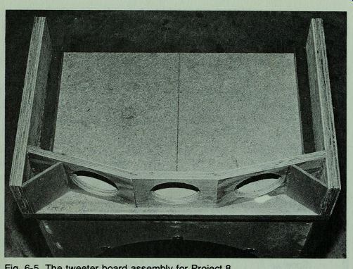
Fig. 6-5. The tweeter board assembly for Project 8.
Prepare and install the tweeter boards. Cut two pieces of 1/8" hardboard to 2.5 x 4' dimensions. Install these pieces with glue at, each end of the tweeter boards, positioned so they extend from the inner front edge of each enclosure side, back to the tweeter boards (Figs. 6-4 and 6-5). Fill any gaps with caulking compound.
If you want to install carrying handles, cut an 18" length of pine 2" x 4" and mount it near the rear of the tweeter compartment with two 5" x 3/16" bolts through the partition. This board should be positioned so that the pulls you mount on the board are accessible from the rear but will not extend beyond the rear edge of the partition or the top (Fig. 6-6). If you use particle board for the partition, put a 1/4" plywood liner under it to hold the nuts on the long bolts. Install the pulls on the 2" x 4" with eight 2" x 3/16" bolts.
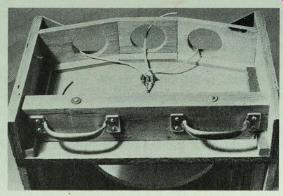
Fig. 6-6. Install tweeter wiring and optional carrying handles before putting
top on cabinet.
Drill a 0.25" hole through the partition and feed a length of lamp cord through it. Seal the hole with silicone rubber sealant. Install a small terminal strip behind the center tweeter board to receive the lamp cord from the woofer compartment. Make connections for the individual tweeter cords (Fig. 6-6). Remember to observe polarity in wiring.
Check your wiring to see that the proper connections are made and the joints are soldered with rosin core solder. Then install the top. Rasp or sand any rough exterior parts. Paint the front of the speaker boards flat black. Use an extra coat on the tweeter boards if necessary to obtain a smooth job. Cut a piece of black expanded aluminum to fit the front of the woofer compartment and glue it down with black GE Silicone II sealant. This metal grille protects the woofer from damage when moving the speaker.
Installing the Vinyl Covering
For a professional look, get a piece of cloth-backed vinyl material long enough to go around the box with no visible seams.
The length from any point on the bottom of the box, up one side, across the top, and down the other side, back to the starting point, is 9 feet 1 1/2 inches. To insure that the piece will reach around the box, add a few inches to the required length. This means that you must buy far more material than is required for a single enclosure, so if you don't mind a visible seam, you can get slightly more than half the required length and split the material lengthwise. To make the seam almost invisible, install the material with a slow setting glue, allowing the two pieces to overlap an inch or two. Then lay a straightedge, such as a large carpenter's square, across the over lapped section and draw a razor blade along the straightedge. Lift the top layer of material to peel off the waste from the underneath piece. When this excess, as well as the top layer waste, is removed, you will have a closely matched seam that will barely show.
Because you will have more width than you need, you can cut the individual pieces in widths of about 18" in order to overlap the enclosure walls by at least 3" at the front and by 1.5" at the rear. After gluing these strips around the edges of the boards, trim the excess material away with a razor blade.
As mentioned earlier, it is easier to make seams with a slow setting glue, such as ordinary white wood glue. The preferred glue for this kind of work is contact cement, but it requires careful alignment of sections before contact with the box is made. This procedure is difficult when using such large pieces of material. For the enclosure shown in the pictures, wood glue was used on the broad sides, and then, after that glue had set, the overlapping edges of material were glued down with contact cement. This procedure permits careful alignment of the large sections, plus the straightedge and razor cutting method for the seam. The material can be folded at the corners to leave a 45° fold down each corner.
Notching the material there will reduce the bulge made by simple folding, and the metal corners will cover any minor mistakes.
The only other difficult matching is in cutting a piece of vinyl to cover the front edge of the shelf which separates the tweeter boards from the large speaker board. Cut a piece of vinyl about 4 inches wide and long enough to overlap the ends of the pieces in place. Use the straightedge and razor technique to match the seam edges, but work quickly before the contact cement has set. The relatively wide strip is suggested so you can trim off the excess at any point you desire. For example, you can let the vinyl extend into the base of the tweeter compartment, covering the top of the shelf.
Install the speakers, using 3/16" x 1" bolts for the large speaker and #6 x 0.5" sheet metal screws for the tweeters. Note that the tweeters are installed from the front of the boards, and the large speaker is from the rear. In wiring the tweeters, note that the positive terminal is on the right solder lug when you look at the tweeter from the back.
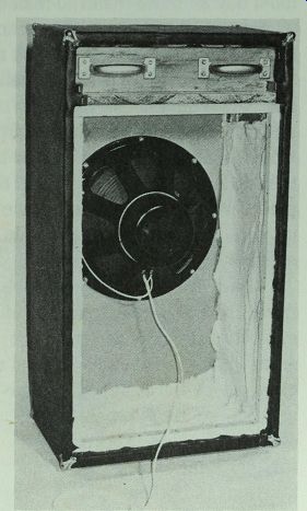
Fig. 6-7. Cleats permit access to woofer compartment through screwed-on back.
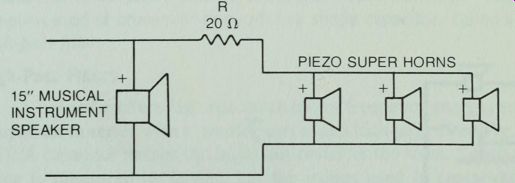
Fig. 6-8. Wiring circuit for Project 8.
No crossover network is needed, but a 20-to 30-ohm resistor should be wired in series with the tweeters (Fig. 6-8). The tweeters are wired in parallel, which causes no problems with most amplifiers, but some amplifiers are "capacitive sensitive" at about 40 kHz. The precautionary resistor prevents such an amplifier from going into oscillation at high frequencies.
To mount the series resistor, install a terminal strip in the woofer compartment. Connect the 20-ohm, 10-watt resistor to the solder lugs. Then break one of the lamp cord conductors from the tweeter compartment and connect the broken ends to each of the lugs. Solder with rosin core solder. Connect the ends of the lamp cord to the woofer. Then connect another piece of lamp cord to the woofer lugs, long enough to reach the terminal strip in the enclosure back (Fig. 6-7).
Next: Crossover Networks