AMAZON multi-meters discounts AMAZON oscilloscope discounts
As mentioned in Section 2, a ported box can be tuned by
altering the area and length of the port. The problem is to know at what frequency
to tune the box for best performance. Another design problem, similar to the
one posed by closed box speakers, is how big to make the box. But first, let's
consider some common types of ported systems.
KINDS OF PORTED ENCLOSURES
There are 3 main kinds of ported box systems: those with a simple hole in the speaker board for a port, those with a tube, or duct, behind the port, and those with a suspended diaphragm, or passive radiator, for a port substitute (Fig. 5-1).
The large enclosure with a simple port of large area is now almost extinct. One reason, we know now that optimum tuning frequency for many speakers is below 50 Hz, and to tune a box to any frequency below 50 Hz without a duct requires a tiny port, which can produce unmusical noises, or a tremendous enclosure, which few homes can tolerate. For example, if you wanted to tune a box to 30 Hz and if you insisted on a minimum port area of 7 square inches, equal to a round port of 3" diameter, the cubic volume of the box would have to be 7 cubic feet.
The most popular method of tuning an enclosure is by a duct which increases the mass of vibrating air and permits lower frequency tuning. One precaution when using a duct is to select a port area that makes the duct shorter than the box depth by 2 or 3 inches. The larger the port area, the longer the duct must be for a given tuned frequency. One must reach a suitable compromise between a minimum port area and a maximum duct length. If an indicated duct length is too great for the box depth, the duct can be bent into an L shape (Fig. 5-2). Where such a duct is needed, you can use plastic drainpipe with a fitted elbow.
Another consideration is the shape of the port opening. Most tuning charts, including the ones shown in this guide, are calculated for ports that are round or square. A long, narrow slot can have a different tuning frequency than a round or square port of the same area, so such extreme variations should be avoided if possible.
If you have a way of cutting perfect circles, you can use a paperboard tube for a port. Such tubes are used by rug manufacturers for shipping cores. You can probably get a tube at no charge from a local furniture store or carpet installer. Cut the tube to the proper duct length, then glue it into the speaker board so it is flush at the front.
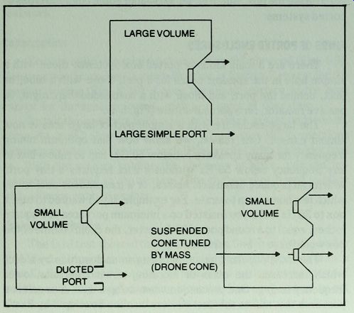
Fig. 5-1 . Kinds of ported enclosures with action at resonance.
Another way to install a duct is to make a rectangular one from W material, such as those illustrated in Project 6. For this kind of duct it is easier to make the hole in the speaker board equal to the internal dimensions of the duct and butt the end of the duct against the speaker board. This means that you must subtract the thickness of the speaker board from the required duct length to get the proper length of the add-on duct. Install this kind of duct with screws or nails and glue.
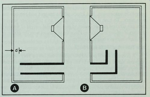
Fig. 5-2. How to install a long duct. A, Wrong if d is less than 3".
B, Right.
Effective length of this duct is distance through center.
Make sure the port is free of any damping material or other obstruction. A port or duct with a smooth inner surface is preferable so that air can move through it easily. This rule should be violated only in problem cases where stuffing the duct makes an audible improvement in the sound. Theoretically it is always bad because a stuffed port can't damp the driver as effectively.
The position of the duct is relatively unimportant if it is located at least 3 inches or more from the woofer. A port that is too close to the woofer will be more susceptible to reflected sound in the upper bass or mid-range. The use of damping material plus adequate distance between woofer and port can reduce this possibility.
The third kind of ported box, with a passive radiator instead of an empty hole, is useful for tuning a small enclosure to a very low frequency. The extra radiator, which is like a speaker cone with no magnet and no voice coil, can be tuned to very low frequencies because the diaphragm has more mass than air in a simple port. For easy tuning, some radiators have a center bolt to which cardboard discs can be bolted. Another method is to glue weights, such as steel washers, to the drone cone. A passive radiator should have high compliance and an effective cone area twice that of the woofer.
An old speaker can be used as a passive radiator if it has a highly compliant suspension. Just knock off the magnet and remove the pole piece. To tune it, use modeling clay as a temporary weight; then use silicone rubber sealer to glue an equal weight of washers or rings of solder to the cone. Place these masses near the center of the diaphragm in a balanced pattern.
HOW TUNING AFFECTS RESPONSE
A properly tuned ported box system can have a very flat bass response curve right down to cut-off (Fig. 5-3). If the box is tuned too high, there will be a hump in the frequency response; if too low, the bass will be weak. In the days of the classic bass reflex the instructions for builders of ported boxes always stated that the box should be tuned to the free air resonance of the speaker. Now we know that the optimum tuning frequency varies for different speakers from frequencies much lower than the free air resonance to frequencies above the free air resonance. It all depends on the Q of the speaker.
For example, a speaker with a high Q will peak at resonance, while a speaker with a low Q will have reduced response at its frequency of resonance. To prevent boom in a high Q speaker, a ported box should be tuned to a frequency well below resonance.
But a speaker with a low Q can be overdamped at resonance unless the box is tuned to a higher than normal frequency.
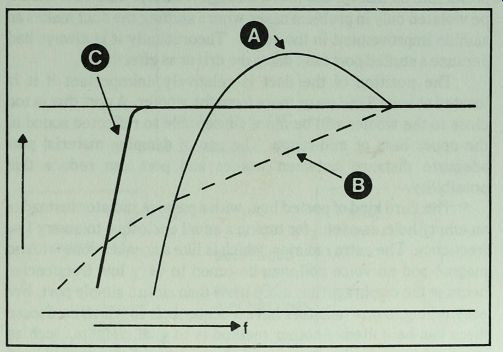
Fig. 5-3. Frequency response curves of bass reflex speaker when enclosure
is tuned to a frequency that is (A) too high (B) too low and (C) optimum.
HOW BOX VOLUME AFFECTS RESPONSE
The effect of box volume on a ported system is much the same as for a closed box speaker: small boxes raise the Q and increase boominess more than do large boxes. This indicates a large box for speakers with a high Q. If a small box must be used, then the speaker should have a high Q with high damping.
Such terms as high and low Q or large and small boxes don't have much meaning without numbers attached to them. For ported box speakers, we can consider speakers with a Q of below 0.38 to be low and those with Qs significantly above that point to be high.
Speakers designed specifically for use in ported boxes have significantly lower Qs than those designed for closed box use.
Whether a box is large or small for a given speaker depends on that speaker's compliance, or VAS. A box that seems large in your living room may be acoustically small for a large woofer. A high compliance 15" driver, for example, can have a VAS of from 20 to 30 cu. ft. , so a 6 cu. ft. floor model speaker cabinet, which would seem extremely large to most families, would be acoustically small for such a woofer. The same floor cabinet would be acoustically very large for an 8" driver with a VAS of 1 cu. ft. The ranks of high fidelity speakers include drivers with specifications that range from one extreme to the other and beyond. These specifications must be considered if you intend to design a ported box for your speaker.
THIELE PORTED BOX DESIGN
A. N. Thiele, an Australian engineer, has brought a high degree of order to the formerly haphazard task of designing a ported box for your speaker. To use the Thiele method, 3 kinds of driver specifications must be considered:
•fs--the driver's frequency of free air resonance.
•Q^--the driver's resonance magnification at f .
•VAS--The driver's compliance, stated in terms of the air volume that has an equivalent compliance for that driver.
Using these 3 values we can determine the 3 critical aspects of a ported box. These are:
1. Box volume (VD).
2. Box resonance frequency (fg).
3. System cut-off frequency (^).
Here we will follow a simplified design process, using charts to obtain factors which, when multiplied by driver specifications, give optimum values (1 and 2). If you want to pursue the design process further, you can use the pocket calculator design method shown in Appendix D. Or, for an even more sophisticated approach, there is the computer program, also in Appendix D. If you have access to a Radio Shack TRS-80 computer, you can quickly design an optimum enclosure for your speaker or readily explore how changes in box volume will change the frequency response curve. With the TRS-80 you can even obtain a predicted response curve for each box volume and tuning condition.
For now assume you want to do the job with nothing more than pencil and paper. Suppose you want to design an enclosure for an 8" polypropylene woofer, Radio Shack Model No. 40-1021, mentioned in Section 4. Here, again, you must consider the parameters of the woofer:
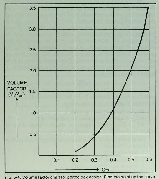
Fig. 5-4. Volume factor chart for ported box design. Find the point on the
curve that corresponds to the Q of your speaker, then move to left margin to
get volume factor. Multiply your speaker's VAs by the volume factor to get
the optimum ported box volume.
f = 30 Hz
Q = 0.41
V_AS c = 2.55 cubic feet
The first step is to find the optimum cubic volume for the enclosure. Going to Fig. 5-4 and following a vertical line upward from 0.41 to the curve, then to the left margin, it appears that the volume factor is equal to about 1. 15. Next, multiply 1. 15 times 2. 55 cu. ft., the woofer's VAS, to get 2.93 cu. ft.
To get the correct tuning frequency (fg) go to Fig. 5-5. Again locate the point on the curve directly above the Q value (0.41) and move to the left margin to get the tuning factor, which appears to be about 0.93. Multiplying 0.93 times 30 Hz (f ), ^ should be 28 Hz.
This completes the basic design, except for the dimensions of the box and port, but it would be helpful to know the bass cut-off frequency, f^ For that you locate the VB/VAS ratio, 1. 15 in this case, along the base of Fig. 5-6. Then move up to the curve and left to the margin to get the bass range factor. In this case, it appears to be about 0.9. The cut-off frequency will be about 0.9 times 30 Hz (f), or 27 Hz.
The charts in Figs. 5-4 and 5-5 are designed to give the optimum values for your woofer. If you want to build an enclosure that is smaller than optimum, you can estimate how much it would limit the bass range by referring to Fig. 5-6. For details on tuning frequency and response variations of such alternatives, use the calculator or computer programs in Appendix D.
Getting the Box and Port Dimensions
You can find the internal dimensions of the box from Fig. 3-1.
That chart shows that the dimensions for 5000 cu. in. , or 2. 9 cu. ft. , are approximately 11" x 18" x 29", if each value is rounded off to the next higher whole number. For more exact work, use a calculator, but such accuracy is unnecessary. These dimensions will allow a bit more than the usual 10 % over-volume, a good practice to follow with ported boxes. Because of unpredictable internal losses, ported systems often need a bit extra volume to reach the performance level suggested by theory.
The final step in box design is to find the correct port area and length to tune the box to 28 Hz. To do that we consult the port design charts in Figs. 5-7 to 5-11. The goal is to find the longest port that will tune the box correctly and yet fit within the 11" box depth with a few inches to spare. We begin with Fig. 5-7, the duct ...
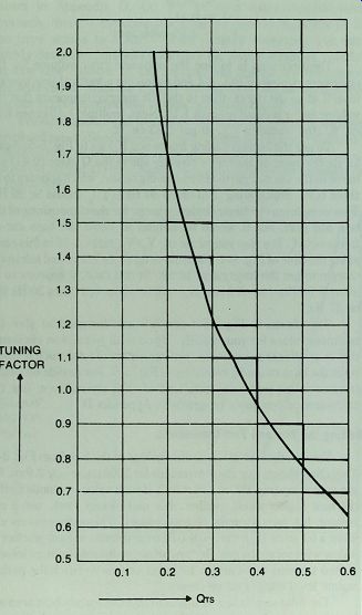
Fig. 5-5. Tuning factor chart. First get the tuning factor that matches the
Q of your speaker. Then multiply the frequency of free air resonance by the
tuning factor to get the correct tuned box frequency (fB).
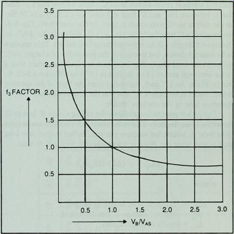
Fig. 5-6. Bass range factor chart. Divide box volume by speaker’s VAS to get
Vb/Vas. Find f3 factor from chart. Multiply f3 factor by speaker's free air
resonance frequency to find the bass cut-off frequency of ported box system.
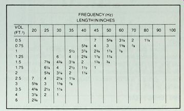
Fig. 5-7. Duct length for port with 3.14 in.^2 of area (2 in. tube).
... with the smallest cross-sectional area. There we find that a 2" tube that is between 1 5/8" and 3" long will tune a 3-cu. ft. box to 28 Hz, so the duct is needlessly small in area. At the next chart, Fig. 5-8, the length of a 3" tube for 25 Hz tuning is8", and for 30Hz, 4 3/4"; so the correct length will be between these two values. This appears to be a useful choice, but to explore the possibility of a larger port, we go to the next chart, Fig. 5-9. Here we find that a duct with a cross-sectional area of 14 sq. in. that is 11" long will tune a 3-cu. ft. box to 30 Hz. An 11" duct, measured from the front of the speaker board, would leave only a 3/4" space at the rear of the duct. The 3" diameter tube is the obvious choice.
Figure 5-9 gave no length figure for tuning a 3-cu. ft. box to 25 Hz with a 14-sq. in. duct. This indicates that it would be too long for most 3-cu. ft. boxes, but suppose you want to find out just how long such a duct must be.
Here is a formula that lets you do that:
ΔL_v = - (Δy (2 L_v / f_B))
where:
ΔL_V = change in vent length in inches
Δf_B = required change in box frequency
L_V = length of original duct
Here, to find the necessary change of length:
L_V = -(-2 Hz) (2 x 11 "/30 Hz)
= (2) (0.37")
= 0.74"
This indicates that we should add about %" to the length of the duct, making it 11 %" long. Such a duct would have to be bent (Fig. 5-2).
Notice that this formula assigns a negative value to the change, showing how much duct to remove when the frequency is too low. For cases where the frequency is too high, as in this one, the change in frequency must be a minus number. The two minuses cancel, giving a positive number that is equal to the number of inches to add.
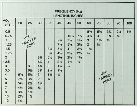
Fig. 5-8. Duct length for port with 7 sq. in. area (3 n. tube).
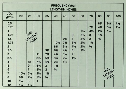
Fig. 5-9. Duct length for port with a 14 sq. in. area(3¾ x 3¾ in.)
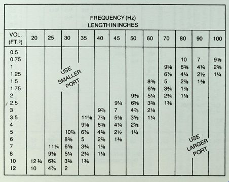
Fig. 5-10. Duct length for pan with a 25 sq. in. area (Sin. x 5 in).
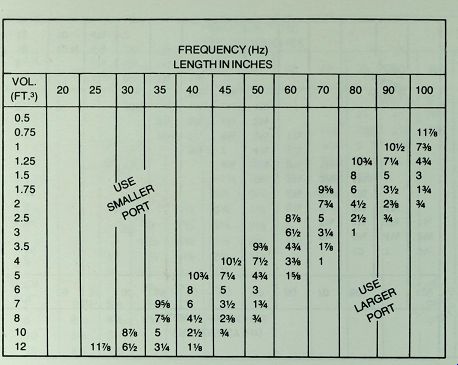
Fig.5-11. Duct length for port with a 49 sq. in-area (7 in. x in.).
FINE TUNING BY EAR
The design process described above is based on Thiele data; however if you happen to find a chart of Thiele's original alignments, you will note that the cubic volumes do not match those obtained by the simplified design method given here.
Thiele's data is based on pure theory, but real systems have losses that prevent perfect agreement between predicted response and measured performance. The cubic volume obtained by charts in this guide allow for about 30 % overvolume, as specified by Richard Small, D. B. Keele, and others, to make up for typical losses. Such losses will vary according to the quality of the box, location of damping material, and even the driver itself. In practice, the 30 % overvolume seems to work well.
If you build a system and find that the bass is slightly weak or, on the other hand, is boomy, you can make the final port adjustments by ear. For example, if the bass is weak, you can tune the box to a higher frequency by shortening the tuning duct. Then listen again. If the bass is boomy, try lengthening the duct, or if that isn't possible, use a duct with a smaller cross-sectional area (Fig. 5-12). You may not get a system that is theoretically perfect by such experimenting, but you can often improve one that looks perfect on paper. After all, you are building a speaker system to listen to, not one to fit some formula.
PROJECT 5: A PORTED BOX SYSTEM
Here is a ported box project based on the enclosure design that was completed in the preceding pages. In addition to the 8" polypropylene woofer, it uses a ferrofluid cooled 4" mid-range speaker and an ultra wide range leaf tweeter (Fig. 5-13). The plans for the enclosure are shown in Fig. 5-14, and the parts list is in Table 5-1.
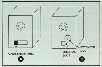
Fig. 5-12. How to lower the frequency of tuning of a bass reflex enclosure
(A) Simple port, reduce port area (B) Duct port, increase length of duct.
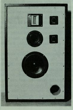
Fig. 5-13. Project 5, complete except for grille cloth.
The wiring circuit for this project is identical to that shown in Fig. 7-12 in Section 7.
Construction
Although 3/4" material is used for the enclosure, some extra bracing is desirable. A single 1" x 4" vertical brace is adequate for the back panel. Glue and screw, or nail, the brace to the back, edge on and just off center.
Assemble the shell. Then install cleats to serve as air stops against the back and front panels. Caulk all joints except the front panel; if instead installed with screws, you can remove it later for changes in tuning. Use foam weather stripping on the back of the speaker board to insure an airtight seal. Apply the weather strip ping just inside the screw line so the screws will not displace it.
Project Conclusion
This system gives excellent performance, particularly with receivers or amplifiers that have a suitable infrasonic filter to eliminate turntable rumble or other low frequency noise.
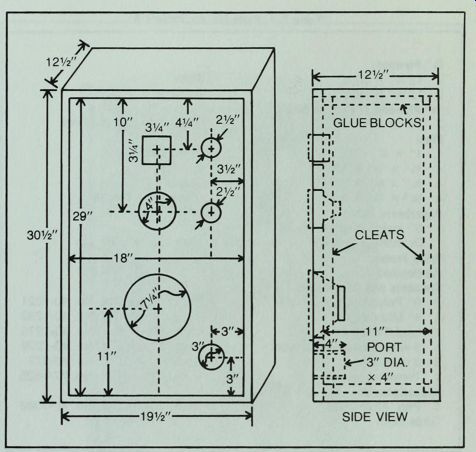
Fig. 5-14. Enclosure plans for Project 5.
Compared to the closed box system with the same woofer, Project 3 in Section 4, this ported speaker offers extended bass range. And the 3-way system, with a control on the mid-range driver as well as the tweeter, permits more careful tailoring of system response. The differences are subtle for some ears, but well worth the extra expense and effort for a serious listener.
PROJECT 6: A DOUBLE CHAMBER REFLEX
Here is an enclosure that enables the 8" driver to give remarkable bass performance. It was inspired by a design by audio engineer George Augspurger, who borrowed the idea from English experimenters.
------------------
Table 5-1. Parts List for Project 5.
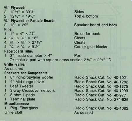
0.75" Plywood:
2 12 1/2" x 30 1/2" Sides
2 12 1/2" x 19 ½ Top & bottom
3/4" Plywood or Particle Board:
2 18" x 29"
Speaker board and back Pine:
1 1" x 4" x 27" Brace for back
4 3/4" x 3/4" x 18"
Cleats 4 3/4" x ¾ x 27 1/2"
Cleats 4 3/4" x 3/4" x 9 1/2"
Corner glue blocks
Paperboard Tube:
1 3" Inside diameter x 4" Port
Or make a port with square cross section 2 5/8" x 2 5/8" I.D.
Grille Frame:
As desired Speakers and Components:
1 8" Polypropylene woofer Radio Shack Cat. No. 40-1021
1 4" Mid-range driver Radio Shack Cat. No. 40-1282
1 Leaf Tweeter Radio Shack Cat. No. 40-1375
1 3-way Crossover network Radio Shack Cat. No. 40-1299
2 8 ohm L-pads Radio Shack Cat. No. 40-977
1 Terminal plate Radio Shack Cat. No. 274-625
Miscellaneous:
1 Pkg. Fiberglass Radio Shack Cat. No. 42-1082
Grille cloth--As desired
-------------------------
Unlike a normal ported box, this one has two chambers. Each chamber is ported, and there is a connecting port in the partition (Fig. 5-16). All three ports have the same dimensions, but the primary chamber, that holds the woofer, has just twice the cubic volume of the secondary chamber. This arrangement allows the enclosure to resonate at two frequencies instead of one. The primary chamber is tuned to about 70 Hz, but at lower frequencies the two chambers act as one large chamber, so the system is also tuned to about 35 Hz. In the enclosure pictured, the lower frequency turned out to be about 32 Hz. This double tuning provides bass reinforcement over a much wider band than would be possible with a single chamber. Moreover, the staggered resonances offer useful speaker damping over a wider band with reduced bass distortion in that range. The soft dome mid-range driver and tweeter complete this unusual system.
Construction
Before cutting out the parts, alert yourself to the asymmetrical layout of the speaker board (Fig. 5-16). To use this arrangement in a stereo pair you should reverse the plan for the second speaker board so that the two speakers will be mirror images of each other.
This can easily be done by inverting one speaker board before gluing on the ducts. Note that you should also reverse the position of the duct on the partition so that the duct is behind the speakers rather than the front ducts.
The front and back panels are glued to the particle board liner and to the partition rather than screwed in because no tuning changes are required with this enclosure. You can add damping to the woofer, if desired, by gluing small pieces of fiberglass to the back of the woofer frame.
Assemble the enclosure shell, then install the particle board liner. Note that the liner pieces should be 11" wide (Table 5-2), to provide the correct interior depth, and it should be installed to leave a 1 1/4" space at the front edge and a 0.75 " space at the rear for the front and back panels. Install the liner with glue and 1" nails or screws.
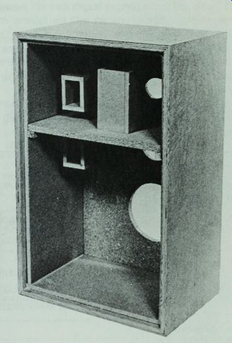
Fig. 5-15. Double chamber enclosure requires 3 ducted ports.
Next, cut a partition from %" particle board. Make this partition 11" wide and to the precise length that will permit it to fit snugly across the box, making contact with the liner at each side.
Cut two pine cleats from 0.75 " x 0.75 " material and install them with glue and 1 1/4" screws, located so their upper edges are 101/16" from the liner under the top. Note that this location will make the upper chamber depth about 95/16" after the 0.75 " partition is installed above the cleats.
Glue strips of veneer to the raw front edges of the plywood sides, top and bottom. Stain and finish the enclosure shell to match your furniture or taste.
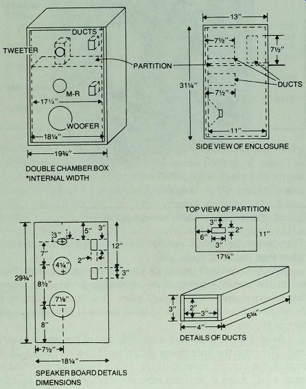
Fig. 5-16. Construction plans for double chamber reflex (Project 6).
------------------
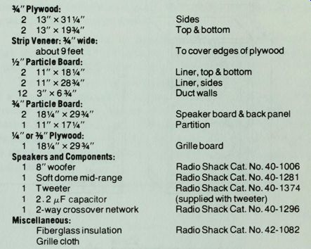
Table 5-2. Parts List for Project 6.
0.75” Plywood:
2 13"x3 1 1/4" Sides
2 13"x19 3/8" Top & bottom
Strip Veneer: 0.75" wide: about 9 feet
To cover edges of plywood
1/2" Particle Board:
2 11" x18 1/4" Liner, top & bottom
2 11"x28 3/8" Liner, sides
12 3" x 6 3/4 " Duct walls
0.75" Particle Board:
2 18 1/4"x29.75" Speaker board & back panel
1 11"x17 1/4" Partition 1/4 " or 3/8 " Plywood:
1 18 1/4"x29.75"
Grille board Speakers and Components:
1 8" woofer Radio Shack Cat. No. 40-1006
1 Soft dome mid-range Radio Shack Cat. No. 40-1281
1 Tweeter Radio Shack Cat. No. 40-1374
1 2.2 nF capacitor (supplied with tweeter)
1 2-way crossover network Radio Shack Cat. No. 40-1296
Miscellaneous:
Fiberglass insulation Radio Shack Cat. No. 42-1082
Grille cloth
------------------------
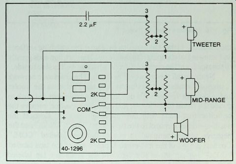
Fig. 5-17. Wiring diagram
for Project 6, using Radio Shack 2-way crossover network, Model No. 40-1296.
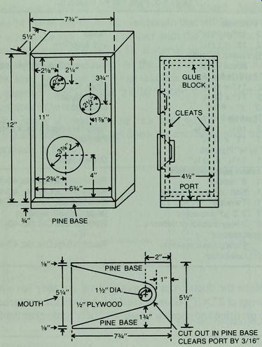
Fig. 5-18. Enclosure plans for Project 7.
Make the ducts from 0.5" material so that they have interior tube areas of 2" x 3". Glue and nail the ducts to the prepared holes on the partition and speaker board. Drill a 1/4 " hole near the front of the partition. Install the partition by gluing the matching surfaces and screwing or clamping it to the cleats. The partition adds greatly to the rigidity of the enclosure, front to back as well as side to side.
Next, install the crossover network. The crossover network is unusual because a 2-way network is used between the woofer and mid-range speaker. To use the 2-way crossover network to divide the signal to the woofer and mid-range speaker, remove the capacitor that came with the mid-range speaker. Connect the positive woofer terminal to the tap labeled "WOOFER 2K" and the negative woofer terminal to one of the taps labeled "COM." Connect pin #1 of the mid-range L-pad to one of the taps labeled "COM" and pin #3 of the L-pad to the crossover tap labeled "TWEETER 2K." Connect pin #1 of the L-pad to the negative terminal of the mid-range speaker and pin #2 to the positive terminal of that speaker. These connections will feed low frequency energy to the woofer and higher frequencies, from 2000 Hz upward, to the mid-range speaker.
The tweeter can be fed from the input to the crossover network through the 2.2 /uF capacitor that comes with it, using an L-pad to control the tweeter's output level (Fig. 5-19) The hook-up above is recommended, but you can save the cost of a crossover network by feeding the mid-range speaker and tweeter through the capacitors that are supplied with each speaker. Do get L-pads. As a refinement to this circuit you can add a homemade choke in series with the woofer. A 0.64 mH coil would be about right. Check Section 7 for details on making your own choke coil.
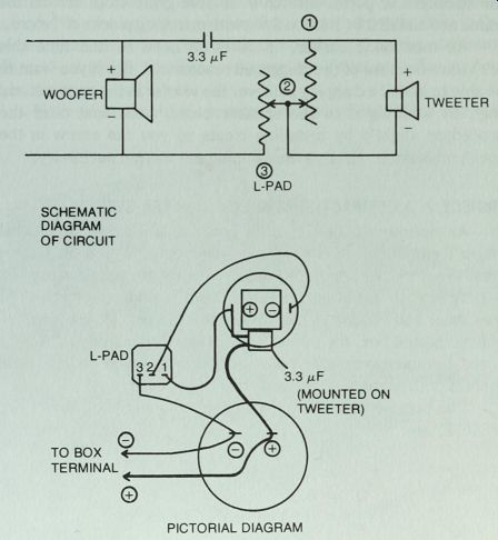
Fig. 5-19. Wiring circuit for Project 7.
Install the crossover components on an 8" x 8" crossover board and glue the board over a 4" x 4" cut-out in the back of the primary chamber. Feed the tweeter leads through the Va" hole in the partition and fill the hole with caulking compound. Caulk all interior joints. Cover the interior of the primary chamber, the larger one, with fiberglass damping material. No damping material is needed in the smaller compartment. Cut the damping material away from the mouth of the port in the partition so that the port is clear of any obstruction.
Glue the speakers to the front of the speaker board with silicone rubber sealant. Allow the sealant to set over night before wiring the speakers, then use a generous amount of silicone rubber to glue the speaker board into the box. Make up a grille frame from 0.25" or 3/8" plywood by making cut-outs at each speaker and port position. The cut-outs should be significantly larger than the size of the speakers or ports. Stretch a suitable grille cloth around the frame and install it by friction fit or with matching pieces of Velcro.
As mentioned earlier, there is no need to fine tune this enclosure because of the staggered resonances. But if you want to be able to install a damping pad over the woofer in the conventional way, by stapling it to the speaker board, you must alter the procedure slightly by installing cleats so you can screw in the speaker board. In our tests the damping pad was not necessary.
PROJECT 7: A COMPACT PORTED BOX SPEAKER SYSTEM
An optimum volume ported box will always be somewhat larger than the closed box for the same woofer (Fig. 4-8). But for small woofers, with a more limited bass range, the advantage of porting is more obvious. The 3 dB down frequency for Project 4 was about 110 Hz. When the same woofer is put into an optimum volume ported box, the cut-off point drops to about 66 Hz. Add an L-pad for more versatile room matching and you have a little system with surprising performance (Fig. 5-19).
The parameters of the small woofer, Radio Shack Model No. 40-1022, are: 0.23 cu. ft. or 397 cu. in.
Using Fig. 5-4, it appears that the volume factor for a Q of 0. 35 is about 0.75. So to get VB, multiply 0.75 x 397 cu. in., the speaker's VAS, to get 298 cu. in. Rounding this off to 300 cu. in. and adding 10 % overvolume, the required volume is about 330 cu. in.
This is too small for the volume chart in Fig. 3-1, but a calculator gives 6.75" x 11" x 4 1/2", for a final volume of 334 cu. in.
From Fig. 5-6 we find a tuning factor of 1.1. So to find L, multiply 1.1 x 55 Hz to get 60.5 Hz, the optimum tuned frequency of the box.
Construction
The only unusual feature of this project is the port. With such a small enclosure, it would be difficult to install a conventional duct large enough in diameter to avoid air noises but short enough to fit in the box. The port used here is based on what G. R. Koonce calls a "diffuser port." In this case the 1.5" hole in the bottom of the box was cut to receive a section of 1 3/8" I.D. plastic drainpipe, but in the final tuning the pipe was found to be unnecessary. The total port is formed by the enlarged opening that extends from the hole in the bottom near one side to the mouth at the other side of the enclosure (Figs. 5-18 and 5-20). The enclosure must rest on a flat surface when in use.
Make your stereo pair in mirror images of each other, reversing the position of the speakers on the second one. Don't expect to fill a gymnasium with sound from such small speakers, but, used within reason, they give exceptional performance for their size and cost.
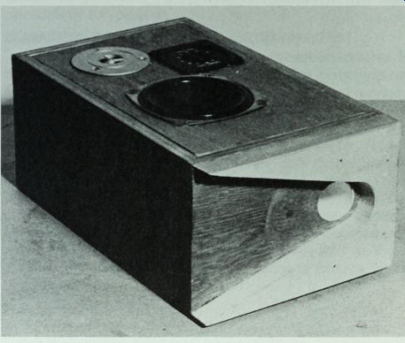
Fig. 5-20. The pine base forms the expanded port for the enclosure of Project
7.
------------------
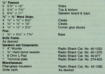
Table 5-3. Parts List for Project 7.
0.5" Plywood 2 5.5" x 12" Sides 2 5 1/2" x 7 %" Top & bottom 2 6 %" x 11" Speaker board & back W x y2" Wood Strips:
4 1/2" x 1/2" X 6 3/4" Cleats 4 1/2" x 1/2" x 10" Cleats 4 V2" x 1/2" x 3V2" Corner glue blocks Pine:
1 3/4" x 5 1/2" x 7 3/4" Base Grille Frame:
As desired Speakers and Components:
1 4" Woofer Radio Shack Cat. No. 40-1022 1 3/4" Hard dome tweeter Radio Shack Cat. No. 40-1 376
1 8 Ohm L-Pad Radio Shack Cat. No. 40-977 1 Terminal plate Radio Shack Cat. No. 274-625 Miscellaneous:
Fiberglass insulation Radio Shack Cat. No. 42-1082
Grille cloth -- As desired
-------------------
Next: Musical Instrument and PA Speakers