AMAZON multi-meters discounts AMAZON oscilloscope discounts
On this page: Closed Box Basic.--How to Fix Box Volume to
Speaker Closed Box Summary-Project 3: A Closed Box System Project 4: An Ultra-Compact
Two-Way Speaker
A closed box is the simplest speaker enclosure you can make, both in principle and in construction. One of its great virtues is that it forgives minor mistakes in box design. There is just one significant design problem to solve: what cubic volume is appropriate for the speaker.
CLOSED BOX BASICS
An unbaffled speaker's resonance is determined by the mass of the moving parts and the compliance of the suspension. When the speaker is installed in a closed box, the pressure of the trapped air in the box restricts cone movement to some extent. In effect, a speaker in a box is stiffer than in free air, and this stiffness raises the frequency of resonance. The smaller the box, the more it raises the resonance frequency (Fig. 4-1).
A certain volume of air itself has no special value of stiffness; that property depends on the size of the piston coupled to it. The air in a box resists the movement of a large piston more than that of a small one. Pressure is measured in force per unit area, such as pounds per square inch (lbs./sq. in.), so for a large speaker cone the pressure must be greater than for a small cone. And when the large cone moves, it changes the pressure against it much more than does a small cone. In fact, the compliance of box air varies inversely with the square of a driver's cone area. Since a 10" speaker has about 4 times the area of a 5" speaker, a given box volume would have 16 times as much "compliance for the small speaker as the larger one. Or, stated in terms of stiffness, the box would be 16 times as stiff for the 10" speaker. If you are ever tempted to squeeze a large woofer into a box that is much smaller than is normally used for a speaker of its size, remember that relationship.
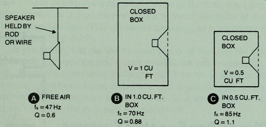
Fig. 4-1 . How a speaker's frequency of resonance and Q varies when tested
in free air and in boxes of different cubic volumes.
Putting a speaker into a small closed box not only raises the frequency of resonance, it also raises the Q (Fig. 4-1). If the speaker is a highly damped model, this may be desirable. Such a speaker may be overdamped if the box is too large. At the other end of the scale, a speaker with a magnet of minimum weight for the size of speaker can sound terrible if put into a box that is too small.
That combination would produce an underdamped system that would boom loudly at resonance. These two factors, the final resonance frequency and speaker Q, make the choice of box volume an important one.
HOW TO FIT BOX VOLUME TO SPEAKER
Many audio fans buy a woofer, then choose a box volume for it.
Sometimes the problem is reversed when the cubic space occupied by stereo speakers must be restricted to a certain pre-set figure.
The problem in the second situation is to find the right speaker for a given box volume.
To get an idea of an appropriate box volume for each common speaker size, look at Fig. 4-2. This chart can be used as a rough design chart for any modern high compliance speaker that will be used in a closed box. Note that there is more allowance for speaker variation for large woofers than for small speakers. The upper line gives maximum cubic volumes; the shaded area shows a range of volumes that vary according to a speaker's compliance and size of magnet.
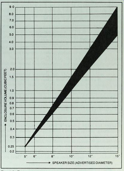
Fig. 4-2. Typical closed box optimum volumes for acoustic suspension speakers.
A variation of 10 % will have non significant effect on speaker performance.
While Fig. 4-2 gives a set of box sizes that are right for most speakers, you may want to explore how variations in box volume would affect the bass range and response curve on your woofer.
After studying Fig. 4-1, some speaker builders might be tempted to install the speaker described there in a larger box than those
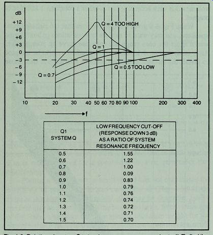
Fig. 4-3. Relation of system Q to low frequency response and cut-off. To find
the cut-off frequency, get the ratio from the chart that is correct for system
Q.
Multiply that ratio by the system frequency, fc.
Example:
System has Ch of 0.9, fc = 70 Hz
Cut-off f = 0.83 x 70 Hz = 58 Hz
... shown in the belief that they would obtain a deeper bass response.
A larger box might produce a weak bass response, due to overdamping, and the speaker's power handling ability would be reduced because the air in the larger box would have less control over the cone. A box can be too small, but it can also be too big for optimum performance.
To predict a speaker's bass performance in boxes of various cubic volume, three specifications must be considered. These are:
•f_s--the speaker's free air resonance frequency.
• Q_TS--the speaker's resonance magnification at fg.
•V_AS--the speaker's compliance stated in terms of the air volume with an equivalent compliance for that speaker.
With these 3 values one can predict, for any suitable box volume, the following system characteristics:
• f_CB--frequency of the closed box speaker resonance, also called system resonance.
•Q_CB--the speaker's resonance magnification in the closed CB box.
•f_3--the frequency where the bass response is down 3 dB, called the cut-off frequency.
To see how different values of Q affect the frequency response of closed box speakers, look at Fig. 4-3. As you can see from the graph, the higher the Q, the greater the hump in bass response near system resonance. The graph in Fig. 4-3 was based on the assumption that each curve represents a closed box speaker system with a system resonance at 50 Hz. If we are comparing curves for a single speaker, the frequency of resonance would be different for each value of Q, with low values of Q associated with a low resonance. That means that the low Q systems can yield a better bass response than is suggested by Fig. 4-3.
Most engineers aim for a CLD that is between 0.7, the value CB with the flattest response curve, and about 1 or slightly greater.
Some rock music fans like a higher Q because it accentuates the bass, accepting speakers with Qs as high as 1.5 or even 2.
Classical music buffs usually want a speaker with a Q_CB under 1.
Knowing how much fullness you can accept in your speaker's bass response can be a useful guide to designing an enclosure for it. If you like prominent bass, try to get the QrD above 1; for refined, LB ultra clean bass, keep it at or below 1.
Here is an example of how to design a box for your speaker, assuming that you know your speaker's specifications. Suppose you have a 10" woofer with the following specifications:
f_s=30Hz
Q = 0.4
V_AS =10cu.ft.
Suppose you want to accentuate the bass slightly, so you choose a final Q of about 1.2. The first step is to find the desired ratio of closed box Q (Q,,J to the free air Q. This can be solved by:
Q_CB/Q = 1.2/0.4 = 3
This ratio will also be the ratio of closed box resonance to free air resonance, so the system will have a resonance frequency of about 90 Hz. But another important consideration is the bass cut-off frequency. Looking at Fig. 4-3, we find that with a Q of 1.2
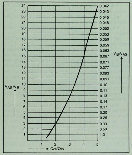
Fig. 4-4. Closed box design chart.
... the bass cut-off occurs at 0. 74 times the frequency of resonance, or, in this case, 0.74 x 90 Hz, or 67 Hz. If you want a more extended response, you could use a lower ratio of QCE/Q, which would also give a lower ratio of fCB/fs Assuming that 67 Hz is satisfactory, what box size should we choose to obtain a Q_CB of 1.2? To find box volume, we go to Fig. 4-4. There we find the desired Q^/Q ratio of 3 and move vertically to the curve, then across the graph horizontally to find the volume factors. The left margin of the chart tells us that we need a VAS/VB ratio of 8, or stated at the right margin in terms of VB as a function of the speaker's VAS, 0.13. To get the correct box volume, we can either divide the VAS by 8 or multiply it by 0. 13, whichever is more convenient. So:
V_B = 10cu.ft./8 = 1.25cu.ft.
Here is a formula that permits you to check the values you get from Fig. 4-4:
A = (QCB/Q)2--1 (where A is VAS/VB) In the preceding example, where a QCB of 1.2 is desired:
A = (1.2/0.4)2- 1
= 32 - 1
= 8
If, for the same speaker, you decide you want to explore the kind of bass range you would get with a Q_CB of 0.7, the Qr ratio would be 1.75. Looking at Fig. 4-4, it appears that the ratio is about 2, so:
V_B = 10cu. ft./2,or 5 cu.ft.
With a box volume of 5 cu. ft. the system resonance would be about 53 Hz, since the resonance ratio is about equal to the Q ratio, or 1. 75 x 30 Hz. Going back to Fig. 4-3, we see that with a Q of 0. 7 the bass cut-off occurs at the resonance frequency, so that would also be 53 Hz. For some kinds of music this would be a better choice, but if the speaker is to be driven hard, there is the question of power handling ability. With a relaxed air cushion behind the cone, the speaker can respond to lower frequency signals, but the cone will move farther, perhaps far enough to cause distortion or even damage at high power levels.
CLOSED BOX SUMMARY
The design procedure outlined above is based on a theoretical speaker with arbitrarily chosen parameters. In most acoustic suspension systems the VAS/VB ratio will be equal to 3 or greater.
For small speakers, with an advertised diameter of 4" to 6", the ratio is often lower, sometimes as low as 1, which gives a Q ratio of 1.414. As you can see, optimum box volume can vary considerably according to the tastes of the builder. But remember these relationships:
• Box Too Large = Weak bass, reduced power handling.
• Box Too Small = Boomy bass, reduced bass range.
If you have a speaker with no specifications, you can use the more general chart in Fig. 4-2 as a guide to an appropriate box volume. Or, if you have some empty shipping cartons of various sizes, you can make some temporary test boxes and try your speaker with each one. Seal the cartons and cut a hole in one side large enough to match the cone area of your speaker. Hold your speaker over the holes in the cartons and listen to its performance with each one. If the bass sounds boomy, try a larger carton. Don't expect good sound with this kind of test; some bass response will be lost because of vibration in the carton walls. The thing to listen for is the frequency of the most prominent bass tones. If these are high enough to significantly accentuate male speech, try a larger box. For more precise tests, see the appendices. Before building a permanent enclosure, look over the construction rules in Section 3.
PROJECT 3: A CLOSED BOX SPEAKER SYSTEM
For this project we will choose an 8" woofer with a poly propylene cone, Radio Shack Model No. 40-1021. The specifications for the woofer are:
fs = 30 Hz Q = 0.41 VAC = 2.55 cubic feet AS
Assuming that a Qrn of 1 is desired, the ratio of QrR/Q should TB CB' be about 2.4. Going to Fig. 4-4 we find that this ratio can be obtained by choosing a VB/VAS ratio of about 0.2, so:
V = 0.2 x 2.55 or 0.51 cubic feet
An enclosure volume of 0.51 cubic feet equals 881 cubic inches. In Fig. 3-1 we find the suggested internal dimensions: about 6 3/8" x 10" x 16". This allows some over volume to make up for the space occupied by cleats and speaker components.
If the Q ratio is 2.4, as calculated, f will equal 2.4 x 30 Hz, or about 72 Hz. With a QCB of 1 the bass cut-off will be (from Fig. 4-3) 0.79 x 72, or 57 Hz. Note that the term "cut-off' doesn't mean that there is no audible base below that frequency; it means that the bass response will be down 3 dB there. Closed box systems give a smooth and gradual roll-off in bass below the frequency defined by custom as the cut-off point.
Crossover Network
The small box makes a two-way system the practical choice (Fig. 4-5). By choosing Radio Shack polypropylene tweeter, Model No. 40-1374, you can build an all polypropylene system (Table 4-1). The suggested low-frequency limit for this tweeter is 3000-Hz, the same as the upper-frequency limit for the woofer. To use the tweeter with a 3000-Hz crossover, a 12-dB/octave filter is desirable.
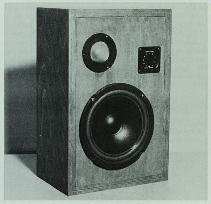
Fig. 4-5. Project 3, complete except for grille cloth.
-----------------
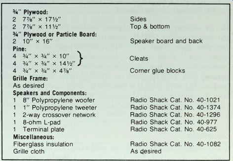
Table 4-1. Parts List for Project 3.
0.75" Plywood:
2, 7 7/8" x 17 1/2" Sides
2, 7 7/8" x 11 1/2" Top & bottom
0.75” Plywood or Particle Board:
2, 10" x 16" Speaker board and back
Pine:
4, 3/4" x 0.75" x 10"
4, 3/4" x 3/4" x 14 1/2" / Cleats
4 3/4" x 3/4" x 4 7/8" Corner glue blocks
Grille Frame:
As desired
Speakers and Components:
1, 8" Polypropylene woofer
Radio Shack Cat. No. 40-1021
1, 1" Polypropylene tweeter Radio Shack Cat. No. 40-1374
1, 2-way crossover network Radio Shack Cat. No. 40-1296
1, 8-ohm L-pad Radio Shack Cat. No. 40-977 1
Terminal plate Radio Shack Cat. No. 40-625
Miscellaneous:
Fiberglass insulation Radio Shack Cat. No. 40-1082
Grille cloth As desired
-------------------
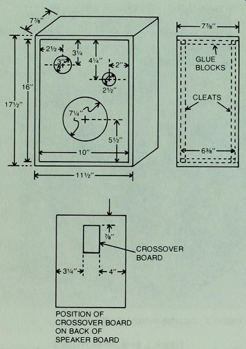
Fig. 4-6. Enclosure plans for Project 3.
Radio Shack's two-way crossover network is a 6-dB/ octave type, and the crossover frequencies are not ideal for this combination of drivers. But it is possible to use this crossover network as a 3000-Hz sharp cut-off filter by an unconventional hook-up (Fig. 4-7). Note that this circuit puts a capacitor in series with the tweeter and a coil across it. Remember to remove the capacitor that is supplied with the tweeter before wiring the system.
Construction
This project uses 0.75" material, such as particle board or a good grade of plywood (Fig. 4-6). Assemble box sides with wood glue.
Then install cleats and corner glue blocks with wood glue. Caulk all joints. Install the back with silicone rubber sealant. Cover all interior walls with a 1" layer of acoustical fiberglass. Install the crossover network on the back of the speaker board with a blob of silicone rubber sealant under it, top and bottom. After the rubber is set, invert the board and install the speakers with silicone rubber and install the L-pad with silicone rubber and the screws supplied with it. Wire the speakers. Then install the speaker board with silicone rubber sealant or latex caulking compound. Reverse the speaker board on your second enclosure so the stereo pair will be mirror images of each other.
Project Conclusion
The final tests on this project showed that f_CB was 74 Hz and Q_CB was about 0.96, very close to the projected figures. The system performed as anticipated, with smooth sound throughout the full frequency range.
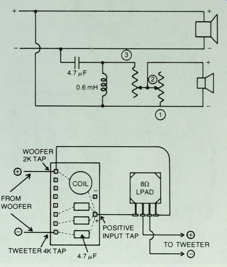
Fig. 4-7. Wiring circuit for Project 3. Un-conventional hook-up gives a 12
/ octave filter for tweeter.
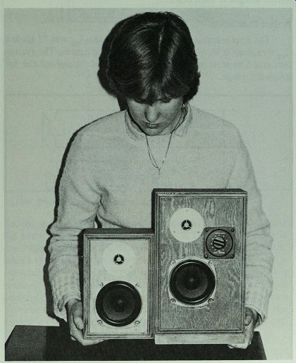
Fig. 4-8. Project 4 and Project 7. The speakers are the same, but the ported
system of Project 7 requires a larger box.
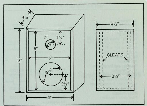
Fig. 4-9. Enclosure plans for Project 4.
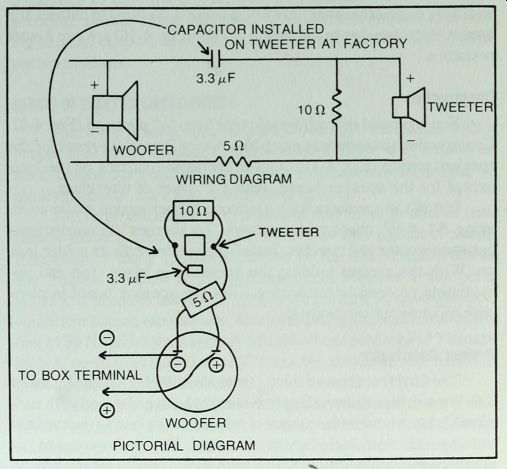
Fig. 4-10. Wiring circuit for Project 4.
PROJECT 4: AN ULTRA-COMPACT TWO-WAY SPEAKER
If your space for speakers is severely limited, this may be the project for you (Fig. 4-8). This 4" woofer, with a Q of 0. 35 and a VAS of 0.23 cubic feet, requires a closed box volume of about 0.08 cubic feet. That translates into 138 cubic inches, a figure below the range of Fig. 3-1. Reference to a handy calculator gives the internal dimension of 3 1/2" x 5" x 8".
For the tweeter we will choose a 3/4" polycarbonate hard dome model, Radio Shack Model No. 40-1376. This tweeter has excellent dispersion characteristics. It comes with a capacitor high-pass filter
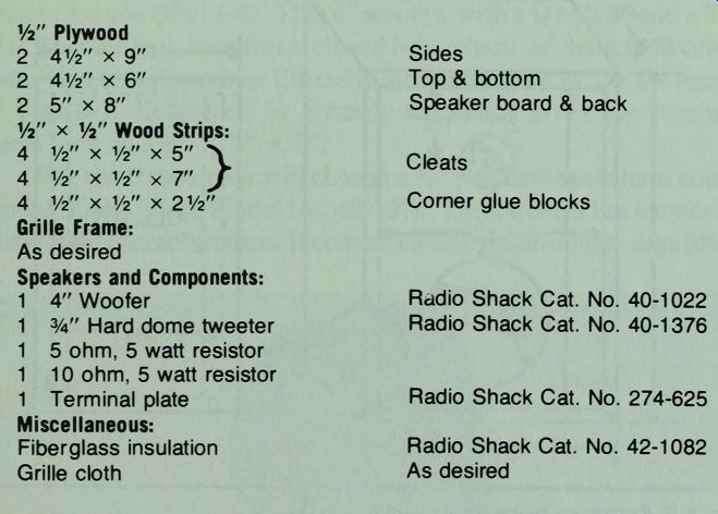
Table 4-2. Parts List for Project 4.
-------------
0.5” Plywood
2 4 1/2" x 9" Sides
2 4 1/2" x 6" Top & bottom
2 5" x 8" Speaker board & back W x 1/2" Wood Strips:
4 1/2" x 1/2" x 5" \ 4 1/2" x 1/2" x 7" y Cleats 4 V2" x 1/2" x 2V2" Corner glue blocks Grille Frame:
As desired
Speakers and Components:
1 4" Woofer Radio Shack Cat. No. 40-1022
1 3/4" Hard dome tweeter Radio Shack Cat. No. 40-1376
1 5 ohm, 5 watt resistor
1 10 ohm, 5 watt resistor
1 Terminal plate Radio Shack Cat. No. 274-625
Miscellaneous:
Fiberglass insulation Radio Shack Cat. No. 42-1082
Grille cloth As desired
----------------------
... wired on, so no crossover network is needed. Serving to balance the output of the tweeter to that of the woofer (Fig. 4-10) are two 5-watt resistors.
Construction You can build this mini-enclosure from 0.5" plywood (Fig. 4-9).
Construction procedure is much like that of Project 3 except for the speaker wiring (Fig. 4-10). Cover the inside surface of the box, except for the speaker board, with a 1" layer of fiberglass.
Install the speakers with a silicone rubber gasket under each, using #4 x 1/2" sheet metal screws. To shorten the connections between woofer and tweeter, install the woofer with its solder lugs up. With the screws holding the speakers in place, you can immediately proceed to the wiring. Glue the speaker board in place with silicone rubber sealant.
Project Conclusion
The final test showed the f_CB to be about 90 Hz with a Q_CB under Ld Lb 0. 6. We would consider a larger system to be overdamped with such a low Q, but when the frequency of resonance is close to the range of male speech, such high damping is useful. You can't expect to get ultra low-frequencies (low bass) from such a small system, but the sound is clean.
Next: Ported Box Speaker Systems