AMAZON multi-meters discounts AMAZON oscilloscope discounts
 .
.
On this page: Appendix A Useful Formulas; Appendix B Tests Not Covered in Section 9; Appendix C Wire Data for Homemade Coils; Appendix D Useful Speaker Design Formulas and Procedures
Appendix A: Useful Formulas
ELECTRICAL UNITS USED IN SPEAKER CIRCUITS
Inductance
The unit of inductance is the henry.
All smaller units should be converted to henrys before using the formulas.
1 millihenry (mH) = 0.001H or 1 x 10⁻³H
1 microhenry (uH) = 0.000001H or 1 x 10⁻⁶H
Capacitance
The unit of capacitance is the farad .
All smaller units should be converted to farads before using the formulas.
1 microfarad (uF) = 0.000001 farad or 1 x 10⁻⁶ farad
1 picofarad (pF) = 0. 000000000001 farad or 1 x 10-12 farad
OHM'S LAW FOR SPEAKERS
For alternating current, the Ohms's Law formulas are:
E = IZ
I = E/Z
Z = E/I
E is the voltage in volts, I is the current in amperes and Z is the impedance in ohms.
Worked Examples:
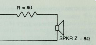
An 8 ohm resistor is put in series with an 8 ohm tweeter.
How much is the sound level reduced? Assume any drive voltage that is convenient; for example, 16 V.
The nature of the speaker's impedance depends on the frequency, so we will assume that it is purely resistive.
Then:
I = 16/16 = 1 A The voltage across the speaker is:
E=1x8=8V
Before adding the resistor, the voltage across the speaker was 16 V. So the ratio of voltage in the new circuit to the old one is:
New voltage/ Old voltage = 8/16=0.5
The dB/voltage ratio chart tells us that for a voltage ratio of 0.5, the output is down 6 dB.
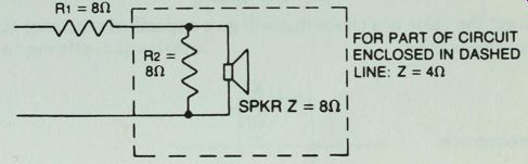
In the same tweeter circuit, an additional resistor is added parallel to the tweeter. What is the tweeter output now compared to its output with no resistors in its circuit? First, get the impedance of the tweeter and its parallel resistor. Since the paralleled resistances are equal, then the net impedance of the tweeter and paralleled resistor branch is 8/2 or 4H.
The total impedance in the circuit is 8 + 4 = 12H.
And:
I= 16/12 = 1.33 A
The voltage across the tweeter and its parallel resistor branch is:
E = 1.33x4 = 5.32 V
And the tweeter's output is:
New voltage _ 5.32
Old voltage 16 ~
From the dB chart, the output is down 10 dB.
REACTANCE & RESONANCE
Capacitors Capacitive reactance:
X =
2ttiC
To get the value of a capacitor that will give a specified reactance at a given frequency:
C =
1 27TfX
Inductance Inductive reactance:
XL= =2 pi fL
To get the value of a choke that will give a specified reactance at a given frequency:
L =
27Tf Resonance f =
2ttvTC Worked example for resonance:
A 1.875 mH choke is wired into a peak suppressor filter circuit with a 7.5 uF capacitor. What frequency will be most affected? f =
1 6.28 V 0.001875 x 0.0000075
= 1342 Hz
Notice that in the formula for resonance, it is the product of L x C that determines the frequency of resonance. You can increase L and decrease C by the proper amounts and still have the same frequency. This permits you to make filters that are effective at the frequency you want with various values of components.
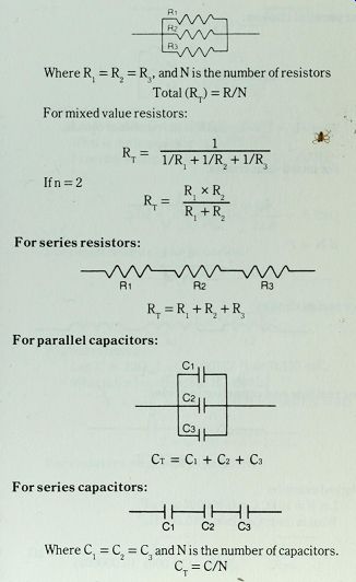
For parallel resistors:
Where R{ = R2 = R3, and N is the number of resistors
Total (RT) = R/N For mixed value resistors:
R .. I t--1/R. + 1/R. + 1/R
* Ifn = 2 RT= lii T R. + R .
For series resistors:
Ri R2 R3 RT = R^R2+R3
For parallel capacitors:
Ci C2 C3 Ih Ct = Ci + C2 + C-
For series capacitors:
C1 C2 C3 Where C = C = C and N is the number of capacitors.
1 2 3 CT = C/N
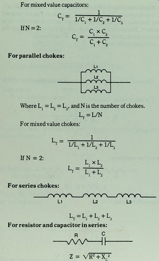
For mixed value capacitors:
1 IfN = 2:
Ct~ 1/C, + 1/C? + 1/C3 C.xC, CT 1 2
For parallel chokes:
Where Lx = L2 = L3, and N is the number of chokes.
L For mixed value chokes:
LT = L/N If N = 2:
L * T_ l/Lj + l/^ + l/^ T L1XL2
For series chokes:
L1 L2 L3 Lx = L^L2 + L3
For resistor and capacitor in series:
R C vwN--IF Z = VR2 + XC2
Worked example:
Let R = 10 n, C = 0.000002 or 2 /LtF.
What is the impedance at 10,000 Hz? X= l -
1 27rfC (6.28) (10,000) (0.000002)
= 8H
And:
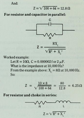
Z = V 100 + 64 = 12.80
For resistor and capacitor in parallel:
RX.
Z =
Vr2 + xc2
Worked example:
Let R = 10n, C = 0.000002 for 2 MF.
What is the impedance at 10, 000 Hz?
From the example above: Xc = 8H at 10, 000 Hz.
So:
Z =
10x8 80 V 100 + 64 12.8
For resistor and choke in series:
= 6.25H R z = Vr2 + xl2
Worked example:
Let R = IOC, L = 0.000127 H or 0.127 mH.
What is the impedance at 10,000 Hz? XL = 27rfL = 6.28 x 10,000 x 0.000127 = 8H So:
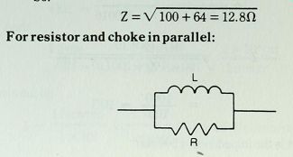
Z=V 100 + 64 = 12.8H For resistor and choke in parallel:
z =
RX.
Worked example:
Let R = ion, L = 0.000127 H or 0. 127 mH
What is the impedance at 10,000Hz?
From the example above:
XL=8H at 10,000 Hz.
So:
Z =
10x8 80
= 6.25H V 100 -I-64 12.8
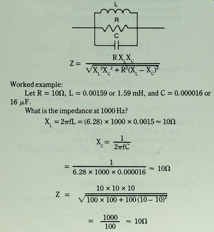
For a resistor, choke, and capacitor in parallel:
L R c z =
RXX L a VXL2XC2 + R2(XL-XC)^
Worked example:
Let R = 10n, L = 0.00159 or 1.59 mH, and C = 0.000016 or 16 /uF.
What is the impedance at 1000 Hz? XL = 2 pi fL = (6.28) x 1000 x 0.0015--10ft 1 Xc 1 Z =
6.28x1000x0.000016 10 x 10 x 10
-ion V 100x100 + 100(10-10)*
= 3SBL--ion 100
What is the impedance at 500 Hz?
At 500 Hz the reactance of L will be halved, compared to 1000 Hz, and that of C will be doubled.
So:X =5HandX = 20H at 500Hz.
L c z =
10 x 5 x 20 V 25 x 400 + 100 (5--20)2 1000 = 1000 V32500 180.3 5.55H
CONVERSION FACTORS FOR SPEAKER COMPLIANCE
Speaker compliance is sometimes measured in cm/dyne--the CGS (centimeter-gram-second) system because the centimeter is a convenient unit to use in measuring cone diameter. Sometimes compliance is shown in mixed units of mm/Newton or even as its reciprocal term--stiffness--in Newton/Meter, the MKS (meter kilogram-second) system.
To change cm/dyne to mm/Newton:
1 cm = 10mm 1 x 10⁵ dynes = 1 Newton So:
10 mm 1 x 10⁵ dynes lcm dyne cm cancels out to:
1 x 10 mm x lxlQ5 Newton Newton 1 x 106 mm/ Newton So:
Cms (cm/dynes) x 1 x 106 = Cms (mm/N)
To change Cms in cm/dynes to stiffness (S) in Newton/Meter, first change Cmx in cm/dynes to S in dynes/cm by:
S = l/C ms And:
ldyne cm 1 Newton 1 x 10 cm
-x 1 x 10b dynes 1 meter cancels out to:
1 Newton 1 x 10² 1 x--x = 1 x 10³ Newton/meter 1x10= 1 meter
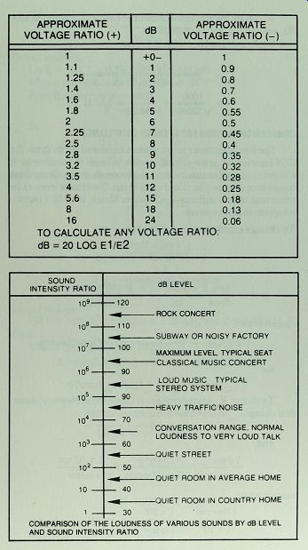
------------ COMPARISON OF THE LOUDNESS OF VARIOUS SOUNDS BY dB LEVEL AND
SOUND INTENSITY RATIO
So: S in dynes/cm x 1 x 10~3 = S (Newton/Meter) Worked example:
The compliance of 12 in. speaker is listed as 0.416 x 10' cm/dynes.
What is the stiffness in N/m? 1 S(dynes/cm) = = 2.4 x 10^6 dynes/cm 0.417 x 10^6 S (N/m) =2.4 x 10^6 dynes/cm x 1 x 10^3
= 2.4xl03N/m
= 2400 N/m

SPEAKER FORMULAS FOR CONSTANT VOLTAGE SOUND DISTRIBUTION SYSTEMS
Power formulas:
p=el Z=E! Z P where:
P = the power in watts, E = the voltage in volts and Z = the impedance in ohms.
TO CHOOSE IMPEDANCE MATCHING TRANSFORMERS:
1. Decide how much power is to be available to each speaker by:
a. Cubic volume and acoustical character of each location.
b. Desired sound level at each location.
c. Available amplifier power-make sure total isn't exceeded.
2. Substitute the transformer primary impedance for Z and the voltage of distribution system for E in the formulas above to find the right impedance transformer.
Worked example: A 50 W amplifier is used in a 70 V line. What impedance transformer is needed where the desired power to the speaker is 10 W.
Z (of transformer) =
(70)2 10 5000 10
= 50on The needed transformer should have a primary impedance of 500H and a secondary impedance to match that of the speaker. No more than five such speakers can be used with this amplifier.
To choose the correct constant voltage transformer tap:
1. Choose a transformer with a matching secondary impedance-an 8 Cl secondary for an 8H speaker.
2. Connect the desired power tap-10W for above example-to speaker.
3. Connect the constant voltage distribution line to the primary.
Appendix B Tests Not Covered in Section 9
These tests require a sine wave generator and an AC voltmeter.
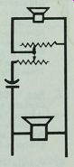
The test set-up is shown in Fig. B-1
IMPEDANCE
Get a 10-ohm precision resistor, 1%, Vfc-watt or greater, for R2 in Fig. B-1. Connect it at points x and y. Adjust generator output to read any 10 units on voltmeter, but choose a point that uses about 10% of the scale. For example, with a 1-volt scale, the reading should be 0.1 volt. After calibrating the generator output with this resistor, the voltage scale can be read in ohms, 0. 1 volt = 10 ohms, 0. 2 volts = 20 ohms, and so on.
Connect the speaker to points x and y. Run an impedance curve, recording values at each 10 Hz interval to 100 Hz, every 100 Hz to 1000 Hz, and at each 1000 Hz interval above that. If your speaker's impedance rises enough to require a higher voltage scale, you can either recalibrate the generator so that 0.05 V = 10 ohms, or get another precision resistor of more than 100 ohms and calibrate to a higher voltage scale.
FREE AIR RESONANCE
Suspend the speaker in mid-air with the cone in its normal vertical position. Vary the frequency from the sine wave generator until you find the low frequency that produces the greatest rise in impedance. Record this frequency as f .
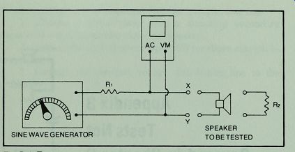
Fig. B-1. Test set-up to measure speaker impedance, free air resonance, and
Q.R_1 = 200 to 1000 ohms.
DRIVER Q
Calibrate an ohm-meter with a 5 to 10 ohm precision resistor.
Measure the DC resistance of the voice coil. Record this value as R.
Set the sine wave generator to the frequency of f . Read the impedance value and record it as Z . Calculate the value of r max o from:
r =
R Record this value.
Find Vr~ and record its value.
Calculate the value of reduced impedance (Z') where:
Z' = Vr xR o e
Find the frequencies below and above f where driver impedance equals Z\ Record these frequencies as f and f2.
Check the accuracy of your work by this test:
The solution to this formula should be accurate within about 1 Hz or 2 %, whichever is greater.
Find the speaker's mechanical Q (Q ) by:
* ms f v7 Q =
M And its electrical Q(Q )by:
Q. =
Qms r -1
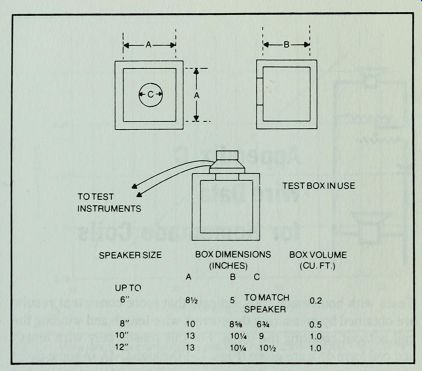
Fig. B-2. Standard box dimensions for testing speakers of various sizes.
Then total Q(Qts):
Q xQ_ Q = Q +<3
Alternate quick method for Q:
Measure R , f , and Z .
e s max Find f and f where Z' = 0. 707 Z .
1 l max Then:
f R Q= T±T*T 2 1 max
Hold the speaker over the cut-out in the standard box. (For dimensions of standard box, see Fig. B-2.) Apply enough pressure to make a good seal. Measure the frequency of resonance on the box. Record this frequency as f . Find V by:
AS VAS = 1.15x [(^L)2_, ] xV(
Appendix C Wire Data for Homemade Coils
Tests with homemade coils indicate that more consistent results are obtained by measuring the correct wire length and winding the coil without counting the turns. For this reason only wire length and coil form data are given (Figs. C-l through C-4). In some cases approximations were made to make chart interpretation easier, but tests with various coils made from these charts showed good accuracy.
If you don't have the gauge of wire specified for a coil, you can substitute a wire of larger diameter, or lower gauge number. Only even gauge numbers are listed in these charts, and if you substitute the next lower even number, say #20 for #22, add 10 % to the specified length. Avoid using wire of smaller diameter than that listed for a choke, if possible.
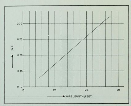
Fig. C-1 . Wire length for homemade coils with inductances from 0. 1 to 0.32
Use #24 wire on 112" core.
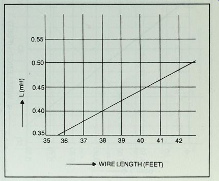
Fig. C-2. Wire length for homemade coils with inductances from 0.33 to 0.51
mH. Use #22 wire on 3/4" core.
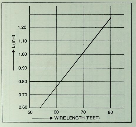
Fig. C-3. Wire length for homemade coils with inductances from 0.60 to 1.28
mH. Use #20 wire on al" core.
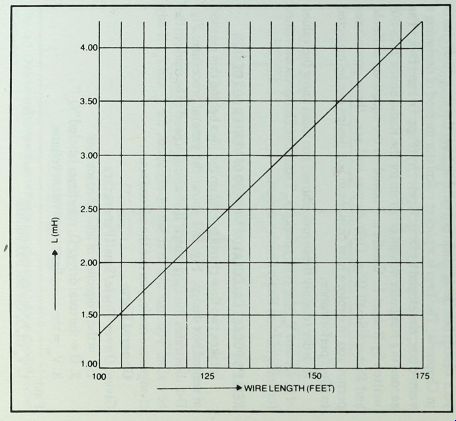
Fig. C-4. Wire length for homemade cods with inductances from 1.4 to4.3 mH.
Use#
Appendix D Useful Speaker Design Formulas and Procedures
Here are two methods of obtaining more detailed information about your vented box design than is available from the simplified charts in Section 4. The first is a pocket calculator method of designing a vented box, developed by D. B. Keele, Jr. (Figs. D-1 and D-2.) The second is a computer design program for the Radio Shack TRS-80, written by Robert L. Caudle and based on the equations of Keele and Richard Small (Fig. D-3) As you will see, these procedures permit you to explore how changes in box design can be expected to affect performance.
In order to apply these procedures, you must know the values of f , Q, and VAS for your speakers. Table D-l shows those values for some current Radio Shack woofers.
KEELE'S POCKET CALCULATOR METHOD OF VENTED BOX DESIGN
It takes two flow charts to explain the idea behind this method of vented box design. Fig. D-l shows the general procedure; Fig. D-2 illustrates the catchy part. If no changes need to be made in the box size, you use the first set of equations for f and f * if any 3 B changes are made, you use the second set.
General Form Given: Driver Thiele/Small Parameters
1. f = the frequency of free air resonance
2. Q = the total driver Q, sometimes labeled "Q "
3. Vas = the compliance equivalent volume.
Find:
1. VD (ft.3), the net box volume
2. fB (Hz), box frequency of resonance
3. f (Hz), the system cut-off frequency, down 3 dB
4. Hump (or dip) in passband.
Procedure:
V =150*^ B as If no change in box size:
l.f =0.26Q14f 2.fB = 0.42Q-09fs
3. The design is optimum. There is no hump or dip.
If any change is made in box size:
n-(/ST)«,.
/ V \ °32 2 ' % = {-c j 9}
3. Hump(dB)=201og 2.6 Q ( "\f" j
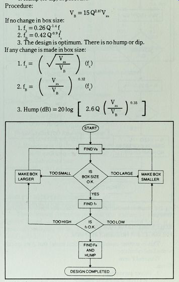
Fig. D-1. Oversimplified flowchart of Keele's pocket calculator method of
vented box design.
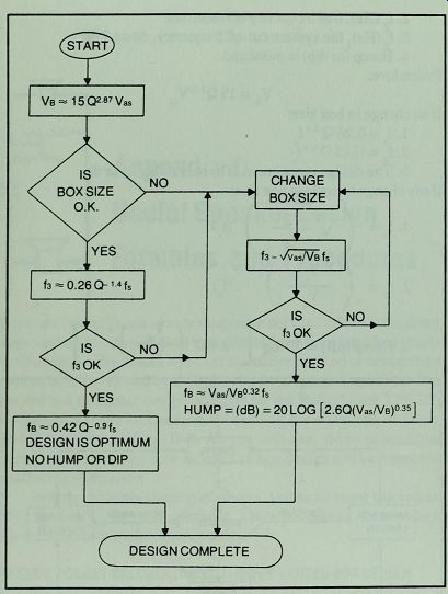
Fig. D-2. Simplified flowchart of Keele's pocket calculator method of vented
box design.
KEELE'S CALCULATOR EQUATION FOR VENTED BOX FREQUENCY RESPONSE
This is another useful mathematical model that goes quickly with a hand calculator.
General Form Given:
1. Driver parameters
a. f (Hz) = free air resonance
b. Q = total driver Q, sometimes labeled "Q "
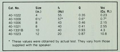
Table D-1. Parameters of Some Radio Shack Speakers
* These values were obtained by actual test They vary fror n those supplied with the speaker
c. V (ft.^3) = compliance equivalent volume
2. Box parameters
a. V, net box volume B
b. f box frequency of resonance .
n.
Compute:
1. Constants a.A = fB7f^2 b.B = A/Q + fB/(7f)
c. C = l + A + f /(7fQ) + V /V
d. D = l/Q + f hfj
2. Response in dB (Normalized to 0 dB at high frequencies)
a. At each frequency f(Hz) Find: fn = f/f
b. Substitute into:
Response dB = 20 Log.
f V (f 4--Cf 2 + A)2 + (Bf--Df ;i)2
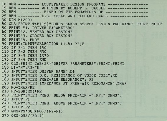
CAUDLE'S LOUDSPEAKER COMPUTER DESIGN PROGRAM FOR RADIO SHACK TRS-80
The following computer program was written by Robert L. Caudle. Based on the equations of Keele and Richard Small, it is especially designed for the Radio Shack TRS-80 microcomputer.
See Fig. D-3.
--------------- Fig . D-3
---------------