by Arthur C. Davis and Don Davis
Microphone sensitivity, do-it-yourself sensitivity measurement, and directionality are discussed in this installment, Part 2
THE FIRST ARTICLE IN this series discussed reinforcement microphones in general and looked into some of the specific characteristics of the moving-coil method of acoustic-to-electric transduction. Going again to characteristics of microphones, in general, we next need to consider the amount of electrical signal the microphone actually generates by means of the acoustic wave.
Microphone sensitivity
Microphone sensitivity, both actual and apparent, can be discussed at this point. Moving-coil microphones, properly designed, can exhibit excellent sensitivity.
Actual sensitivity can be best visualized by recognizing the following: Some sounds can have such a low SPL at the frequency at which they occur that the pressure exerted on the microphone diaphragm does not create sufficient voltage to override the voltage generated by the internal impedance of the microphone itself. (This "self noise" is the reason carbon microphones aren't used in reinforcement work.) In other words, one microphone's "self noise" may be great enough to mask a signal that is clearly reproduced by a second microphone with a lower "self noise" threshold. From this consideration, coupled with the level at which the diaphragm and/or voltage-generating mechanism overloads (due to excessive acoustic pressure) , the dynamic range of the microphone can be calculated.
Here is a common misconception regarding microphones: If you connect two microphones into a mixer amplifier, whichever mixer control is set lowest for the same SPL at the microphones indicates the most sensitive of the microphones. This is not entirely true. While it is an indication of the effective output of the microphone, and as such aids in designing input amplifiers, among other circuits, it does not tell the operator which microphone will pick up and reproduce weak sounds with the least noise.
Factors to be considered in evaluating "self noise" in microphone systems is shown in Fig. 1. When extremely quiet studios are used, all of these factors become almost equal in value if all design parameters are maximized. (Barkhausen noise is an exception to this. It is usually much lower in level than the other noise sources.) Apparent Sensitivity. Apparent sensitivity is another matter. Conversion charts in Fig. 2 allow quick conversion of a manufacturer's microphone ratings. The number of conversions that the chart and data sheet supplies indicates the complexity, confusion and consternation that microphone users face when approaching a strange manufacturer's new offering for connection to an existing sound system. The illustrations also allow a quick calculation of the point where microphone out put drops below the sound system's electronic "equivalent input noise" (EIN) figure.
-------------
USING THE MICROPHONE SENSITIVITY CONVERSION CHART
Microphone sensitivity can be specified by several different methods. To properly compare the rated sensitivity of two different microphones, their sensitivity ratings must be converted to the same method. The nomograph in Fig. 2 gives the relationship between:
1. The open circuit voltage (S_v). This is normally specified as dB above or below 1 volt if a sound pressure level of 1 microbar drives the microphone diaphragm.
2. The open circuit power (S_p). This is normally specified as dB above or below 1 milli watt if a sound pressure level of 10 microbars drives the microphone diaphragm.
3. The RETMA sensitivity rating (G_m). This is normally specified as dB below 1 milli watt if a sound pressure level of 0.0002 microbars drives the microphone diaphragm.
Finding the RETMA.Impedance Rating (Rmr)
To find (Rmr) locate the impedance on the Nominal Impedance in ohms scale. These values appear along the base of a triangle which has for a peak the (R_mr) values (left hand side of scale). For any nominal impedance along the base of a triangle use the value given at the peak of that triangle. (RETMA impedance ratings do not extend below 19 ohms.) Example of Chart Use Have: A microphone with an open-circuit voltage rating of 1 millivolt (-60 dB) and a nominal impedance of 15,000 ohms.
Find: 1. Power level sensitivity
2. RETMA sensitivity rating Solution: 1. Connect (Su) to nominal impedance in ohms with a straight line (solid line on chart in Fig. 2). Read power level sensitivity from (Sp) scale (-58 dB)
2. To find the RETMA sensitivity rating, locate the RETMA impedance rating.
Looking to the left of 15,000 ohms on the nominal impedance scale, we see that 15,000 ohms is along the base of the triangle with 9600 ohms as its peak. Connect 9600 ohms to the open-circuit voltage on the S_v scale (-60 dB), the dotted line on chart, and read the RETMA sensitivity rating on the (Gm) scale (-150 dB) Finding Open-Circuit Voltage Sensitivity of Microphones Undergoing Impedance Transformation
1. First find the power sensitivity (S_p) rating of the microphone at its original impedance. Using the (S_p) reading as a pivot point, realign with the new impedance rating. The open-circuit voltage may then be read on the (S_v) scale.
References: RETMA Standard SE-105 "Microphones for Sound Equipment"--ASA Standard 224.1 "Acoustical Terminology".
--------------------
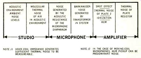
Fig. 1--Sources of self-noise in microphone systems. --- NOTE #1 VOICE-COIL
IMPEDANCE GENERATES SUFFICIENT THERMAL NOISE TO BE MEASUREABLE. NOTE #2 IN
THE CASE OF MOVING-COIL MICROPHONES, HUM PICKUP CAN BE PREDOMINANT NOISE.
In using microphones in professional sound system work, every effort should be taken to obtain accurate, reliable threshold figures from the microphone manufacturer being specified.
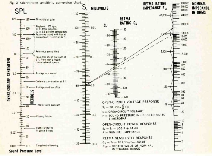
Fig. 2--Microphone sensitivity conversion chart. OPEN-C RCUIT VOLTAGE RESPONSE
Sv = 20 LOG,o E dB E = OPEN-CIRCUIT VOLTAGE P = SOUND PRESSURE IN dB REFERRED
TO 1 MICROBAR OPEN-CIRCUIT POWER RESPONSE SP=SvLOG R-}-44dB R = NOMINAL
IMPEDANCE RETMA SENSITIVITY RESPONSE GM = Sv 10 LOGIoRMR -50 dB RMR = CENTER
VALUE OF NOMINAL IMPEDANCE RANGE
Do-It-Yourself Measurement. In designing a control console for a sound reinforcement system in which a microphone you are not completely familiar with (and in many cases, those you think you are familiar with) is to be used, the following test is invaluable:
(1) Set up q test speaker in the manner shown last month (first article in the series) for measuring acoustic gain.
(2) Place this test speaker two feet in front of a sound level meter (SLM) and right on its most sensitive axis (0° incidence) .
(3) Using the SLM in the exact position the microphone to be tested will occupy, set the test loudspeaker (using random noise for a source) to a reading on the SLM of 100 dB SPL. (This is the typical SPL generated if the lips are pressed against the microphone while talking.)
(4) Now substitute the microphone to be tested in place of the SLM. The output of this microphone will be led to the input of the microphone preamplifier used in the console; output impedance of the microphone should match the nominal source impedance of the microphone preamplifier. (Since microphones are not normally terminated at the input of the microphone preamplifier, and the actual input impedance of the preamplifier is usually many times that of the nominal source impedance rating; measurements of the microphone output alone does not tell the whole story.) Terminate the output of the microphone preamplifier in its rated load, read the output level in dBM and examine the waveform with an oscilloscope. Many times at this point, it will be discovered that the microphone preamplifier is being grossly overdriven. Therefore, an input loss pad ahead of the preamplifier would be required (or else a less sensitive microphone) . It is not unheard of to encounter output levels from microphones that exceed-15 dBm in actual service (for example, a trumpet blown into it at 130 dB SPL) . In the case of a typical high-quality preamplifier with a gain of 51 dB, the output level would have to be +36 dBm. (In this case, the actual maximum output level for rated distortion of this amplifier is + 27 dBm.)
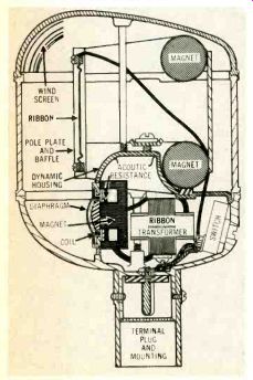
Fig. 3--Ribbon and moving-coil microphone share the same case.
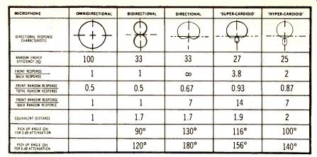
Fig. 4--Directional response characteristics of microphones
The natural solution is to insert at least a 20 dB loss pad ahead of the preamplifier. (A bridging-type pad is often used to avoid loading the input of the preamplifier.) Overdriving the very first amplifier stage is more common that is ordinarily realized. Most sound engineers don't believe it until they try this test on one of their own sound systems.
Microphone directionality
The first carbon microphones made were of the pressure type and exhibited essentially omnidirectional response. These were followed by the early condenser microphones developed by Wente and Thuras of Bell Telphone Laboratories.
Ribbon Microphones. The development of directional microphones began with the ribbon microphone.
The ideal ribbon microphone presents a ridged surface supported by corrugated suspension at each end, allowing the working length of the ribbon (the part that cuts the magnetic field of force) to move as an unflexed plane through the magnetic lines of force.
This metallic ribbon is suspended in the magnetic field and is freely accessible to air vibrations from both sides. The ribbon responds to the difference in pressure between the front and the back surface. In other words, it responds to the pressure gradient or the particle velocity. The electrical output waveform of a ribbon microphone follows the same rules as does the moving-coil microphone. While the ribbon responds directly to the particle velocity of the sound wave, it generates its voltage proportionally to the velocity of the ribbon in the magnetic field.
(See Fig. 3, where a ribbon and a moving-coil microphone share the same case.) If a wave in a far field approaches the ribbon at 90° to the front axis the result is no pressure gradient between the front and back of the ribbon; therefore, no movement of the ribbon. This makes the ribbon microphone a highly efficient bi-directional microphone. (See Fig. 4.) In studio usage this directional pattern can be useful in discriminating against unavoidable ambient noise.
The ribbon microphone suffers three handicaps to widespread use in reinforcement systems, though careful professional users do achieve exceptional results with them (even outdoors) if their limitations are thoroughly understood and compensated for:
1. The ribbon is fragile, easily damaged by wind. (Also, it is easily damaged by being knocked down or dropped.) Thus performers should not (as they often do) test the microphone by blowing into it. When it can be shielded from the wind (such as in a wind-free theater in a protected ravine) , or mounted where the performer cannot get closer than 6 feet from it (overhead or the far side of the footlights) , damage can be minimized. To meet a psychological need, the performer can be given an empty case to carry in his hand while the pickup is made from overhead.
2. The ribbon microphone should not be used where it must be mounted near a large surface. Ribbon microphones placed against a wall lose sensitivity, for example.
(The sound wave reflects off the wall to the rear of the ribbon, destroying the pressure gradient. The maximum response of a ribbon microphone will occur 2N lambda /4 from the wall. In the case of the moving-coil pressure-type microphone, the greatest output will occur if it is placed next to the wall since its maximum response occurs at the surface of the wall and at intervals of 2N X/4 from the wall.
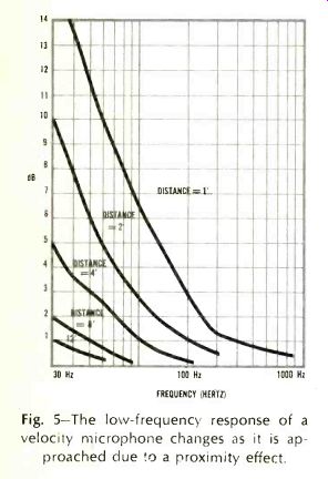
Fig. 5--The low-frequency response of a velocity microphone changes as it
is approached due to a proximity effect.
3. As a ribbon microphone is approached, its low frequency changes.
This proximity effect is charted in Fig. 5. There is a real necessity to keep performers away from this microphone for best results.
* N = an integer, X = wavelength
The ribbon microphone makes an excellent narration microphone in studios but is usually misused by being placed on the table in front of the narrator rather than on a boom over his head.
It should be mentioned that some performers have used the proximity effect to generate special tonal characteristics. In cases of this type, the microphone is used as a generating rather than as a reproducing instrument, and fidelity is dispensed with.
Cardioid Microphones. Cardioid means heart-shaped, and refers to the plane view of the polar pattern.
Once the moving-coil pressure microphone and the ribbon velocity microphone were on hand, mathematically-minded people quickly saw an advantageous summation of their voltage outputs. Fig. 6 illustrates the results of such a combination--the cardioid microphone.
It is necessary to remember, in both the case of the cardioid and the velocity microphone, that the polar patterns, while illustrated in two dimensions, exist in three dimensions.
That is, an omnidirectional microphone polar pattern is not a circle, but a sphere. The polar response of a bi-directional microphone resembles two spheres, and a cardioid's response resembles a pumpkin, with the microphone located at the stem position.
In well-designed microphones, the vertical polar response will closely approximate the . horizontal response. (Many mysterious problems have been solved by discovering that, in "bargain microphones," the horizontal and vertical polar characteristics were not the same.
The ability to vary the rear lobe on a directional microphone is the best known method of picking up both a weak voice and a strong voice in the same area. Placing the strong voice on the rear side of the microphone allows you to attenuate it (relative to the weak voice). The cardioid pattern can also be obtained from the moving-coil microphone alone if access to the rear of the diaphragm by the sound wave is carefully planned in relation to phase.
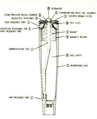
Fig. 6--Cross-section of a typical cardioid microphone.
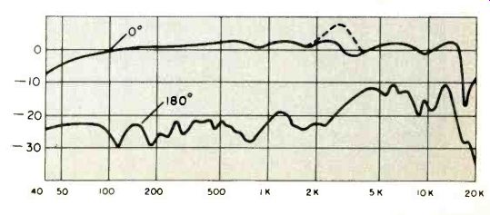
Fig. 7--Frequency response on 0° axis
Figure 6 shows the internal construction of such a microphone, with its rear ports for high and low frequencies and the necessary communication tubes.
Fig. 7 details the frequency response taken first on the 0° axis, then on the 180° axis. Sound reinforcement engineers must be careful to avoid microphones whose 180° response introduces detrimental amplitude or phase changes, thereby triggering premature feedback problems. Recording and broadcast engineers, however, can safely ignore such details. (Where a Radio-TV show includes sound reinforcement to a live audience, an acoustical engineer is a worthwhile consultant to have available.)
Condenser-type Microphones. The condenser-type microphone comes closer to the perfect transducer than any other practical microphone in use today. (This is not to say that poor condenser microphones are not produced, but the potential for superior performance is inherently available in the condenser microphone.) There are drawbacks, too, to be sure, including high cost relative to other types, bulkier size and potential for breakdown due to the need for a power supply.
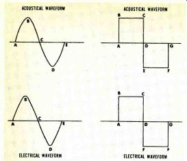
Fig. 8--Condenser microphones
generate output
signals in step
with acoustic
waves.
Here are some of the advantages that the condenser microphone offers over other types:
1. Diaphragms with the least mass and greatest rigidity, yet providing sufficient output.
2. Smoothest, most extended, and most stable frequency response (witness the measuring microphones, such as: the Western Electric 640AA, Altec 21BR series, and the Bruel & Kjaer series, among others).
3. The most ruggedness and endurance. They can be designed to withstand high SPL. They are used to measure over-pressures during rocket launches, and exhibit exceptional freedom from temperature changes.
(In its original form, the condenser microphone was not so rugged. An American recording expert, carefully smuggling home the first post-World War II European condenser microphone system, found that it had a large gold sputtered diaphragm, against which was a pressure-type electrical contact. The microphone had been brought back on a propeller-type aircraft, it seems, and the steady excitation of the diaphragm by the large amplitude, low frequency engine noises had worn the gold off the diaphragm at the contact point. The diaphragm was re-sputtered, making the unit operational again.)
4. They generate an output electrical waveform in step with the acoustical waveform and can be adapted to measure essentially d.c. overpressures. (See Fig. 8.)
5. They provide the lowest noise and highest sensitivity. The proper use of the capacitor head to control a small FM oscillator can result in exceptionally low-noise microphone performance when electronic stability of the oscillator circuit is carefully maintained.
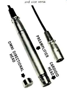
Fig. 9--Some condenser microphones offer
the flexibility of changing heads from omnidirectional types to unidirectional
types and vice versa.
6. Because of small head size, they provide the least diffraction interference of any microphone type.
This does not apply where, due to styling or other causes, the condenser microphone is made physically large. Because diffraction problems appear at that frequency where the wavelength/4 = the diameter of the front of the microphone, it can be calculated why the very best quality microphones have diaphragms that range between 1/2-in. and 1-in. in diameter.
7. Versatility. It is possible to use one preamplifier base and carry both an omnidirectional head and a unidirectional head in your pocket to meet whatever requirements the situation at hand calls for. (See Fig. 9.) The concluding article of this three-part series will continue next month.
(Audio magazine, Jan. 1968)
Also see:
AUDIO EQUIPMENT PROFILES (Jan. 1968)
ABZs of FM, Leonard Feldman
= = = =