This Month: Jensen Model S-100 Stereo Speaker System; Concord Model "Mark III" Stereo Tape Deck; Kenwood "Supreme I" Multi-Channel Stereo Amplifier; H. H. Scott Model Q-100 Speaker System; Jensen Model S-100 "Stereo 1R" Stereo Speaker System
Jensen Model S-100 Stereo 1 Speaker System
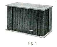
Fig. 1
MANUFACTURER'S SPECIFICATIONS:
Input Impedance/channel: 8 ohms. Power Rating/channel: 35 watts program material. Frequency Range: 30-20,000 Hz. Finish: Walnut Veneer. Dimensions: 13" H x 21 3/4" W x 11 9/16" D. Weight: 26 1/2 lbs. Price: $124.95.
A scientifically legitimate "one-speaker system" stereo reproducer has been sought for many years. Small-apartment dwellers, and other decor-conscious high fidelity enthusiasts had long hoped for it, while self-sacrificing wives of audio buffs fairly begged for it.
The Jensen Manufacturing Div. of the Muter Company, amidst a flurry of publicity, introduced its answer to this quest recently. Dubbed "Stereo In", the first of what will probably be a series of "one-enclosure" stereo speaker systems is the modestly priced (when one considers that only one unit is required) Model S-100. Smartly styled and constructed in the "bookshelf"-enclosure tradition, the system looks quite conventional from the outside, as shown in Fig. 1.
The first clue to its uniqueness is, perhaps, the wrap-around grill-cloth treatment, which covers about half the side surfaces as well as the front radiating surface of the enclosure. This suggests loudspeakers oriented to produce "side firing." Our first skeptical conclusion was that Jensen had merely reverted to the old technique of "mixed lows" directed forward, with middles and highs of Left and Right radiated sidewards by means of two lesser speaker elements mounted on the left and right inside walls of the enclosure.
This "compromise" solution has been used by console manufacturers for years and about all that can be said for it is that you sense some stereo effect if you put your nose about six inches from the surface of the console face.
Happily, the system introduced by Jensen is much more sophisticated than that-and, more importantly, IT WORKS! Although we read a full description of the theory behind this acoustic "break-through," we had to examine it for ourselves, and so we opened the back of the enclosure. On the inside of the back, we found a transformer hooked up to the input terminals and to the speaker elements below. A detail photo of this "matrixing" transformer is shown in Fig. 4.
Inside the enclosure, about half way down the "depth" dimension of the enclosure, we saw a single, 8-inch loudspeaker with its hind end facing us, as can be seen in the photo of Fig. 2. We removed this baffle, turned it over, and saw what is depicted in Fig. 3, photographically, as well as the line diagram of Fig. 5, which we shall now use to explain how single-box stereo is not only possible, but in some ways actually gives a more total "surround" illusion than the more conventional two-speaker arrays.
Acoustic Matrixing
As mentioned, the larger 8-in. speaker element affixed to the main baffle is a front radiator. A "median plane baffle," mounted perpendicular to the 8-in. unit and directly across its diameter, houses two 5-in. wide-range speakers facing in opposite directions.
Electrical connection to these two speakers is made in series, but the two speakers themselves are connected out-of-phase. Furthermore, thanks to the transformer matrix network, the signal fed to this array is actually a difference signal, or (L-R), whereas the signal fed to the forward radiating 8-in. element is a sum signal, or (L+R). There are, therefore, three acoustic output signals present, as follows: (L+R) from the 8-in. unit radiating in a forward direction.
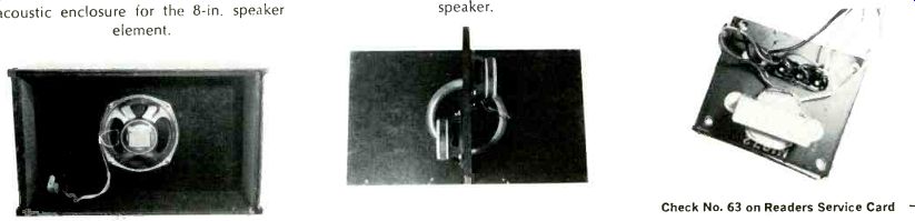
Fig. 2---With the back of the new Jensen S-100 Stereo 1 removed, only
about 1/2 the total cubic volume acts as an acoustic enclosure for the 8-in.
speaker element. Fig. 3---The inner structure reveals positioning of two side-firing
5-in. wide-range speakers, as well as the 8-in. (L+R) speaker. Fig. 4---Shown
here is the matrixing transformer located on the inside of the enclosure's back.
(L-R) from the "median plane array" aimed to the left.
(LR) from the "median plane array" aimed to the right.
If you are at all familiar with stereo FM transmission, you will realize that [...]
(L+R +(L-R)-L+R+L-R-2L L+ R+ [(LR)] L+ RL+ R-2R
electrical matrixing very similar to the acoustic matrixing devised here by Jensen is exactly what is required to establish (or reestablish) a distinct "L" and "R" signal. The matrixing equations are those shown in Fig. 5.
namely: (L +R) + (L -R) 2L and (L +R) (L -R) 2R
The amazing thing here is that the matrixing takes place acoustically, or, more probably, psychoacoustically, for there is, without question, stereo "separation" way in excess of the physical confines of the small enclosure.
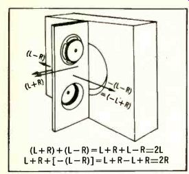
Fig. 5-Drawing reveals how Jensen's "Stereo 1a" accomplishes acoustic matrixing.
In much of the program material to which we listened, we heard "virtual sound sources" all across the "stage wall" and even some in front of and behind the so-called "stereo wall of sound." At first hearing we really did a "double -take" because all previous experience told us it couldn't be happening. But it was! There are two very interesting additional advantages that soon become apparent when listening to the S -100. First, there is absolutely no "hole -in -the middle" effect. How could there he? The speaker system is in the middle! Just as important, however, is the fact that there is also no undue predominance of sound emanating from the center region. It is really well distributed. Finally, when we switched to monophonic operation, the system behaved just as it should have.
Since, under these conditions, "L" and "R" outputs from the amplifiers are equal, there is no difference (L -R) signal and all sound therefore radiates from the single, wide -range speaker system (8 -in.) in a forward direction; monophonic without question. In this listening mode we did notice an apparent diminution of highs in some listening positions, but we must attribute this to the fact that the 8 -in. unit is perhaps less responsive to ultra highs than are the two 5 -in. units which radiate sideways during stereo programming. In the S -100, at least, we concluded that its overall response and angular dispersion is actually superior in stereo than in mono listening.
Jensen states that, "Actual measurements of the performance of this unique loudspeaker system are most difficult because we are dealing with a stereo system just as we would be if we wanted to measure the performance of two monophonic loudspeaker systems separated in the orthodox fashion for the stereo loudspeaker system." We found this to be true in that free -air frequency response measurements on axis would have been somewhat meaningless. We therefore had to resort to purely subjective listening in most of our tests.
As always, however, we were concerned with how speaker impedance might vary over the audible range.
Measurements of impedance for one channel are shown in Fig. 6 and, as can be observed, there is no problem here since the impedance characteristic is uniform. The unit (s ?) are therefore safe with any amplifier that can feed a 4-ohm or higher impedance. The individual speaker elements used in the makeup of the S -100 are fairly high in efficiency, despite the "soft" suspension characteristic of Jensen's Flexair' line of speaker elements.
The S -100 has a single common connection for the "ground" wires of left and right speakers.. The center terminals, designated as common -left and common right, are actually connected to each other behind the terminal strip panel, inside the enclosure. Thus, you need run only a three -conductor cable from amplifier to speaker system.
Check your amplifier or receiver instruction manual, though, because this could create a problem with some units. This would be a rare case, though, and if it exists would generally be with an older amplifier whose instruction manual would caution users about it. We might suggest to Jensen that a two primary matrix transformer could easily solve this problem -Ed.
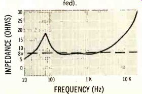
Fig. 6 -- Impedance characteristic of Jensen S -100 stereo speaker system
(one channel fed).
Ten to 15 watts of clean amplifier power is all we really ever needed for room filling sound. Furthermore, the mid -range tones of this system seemed full -bodied. Bass tones were clean down to about 60 Hz, or so, but were deficient in amplitude from about 100 or 150 Hz downward. (It should be remembered that the largest diameter speaker element in this entire system is only 8 inches and that this element is equipped with less of a magnet slug than even its five -inch side radiating companions.) Angular dispersion of highs was excellent when listening in the stereo mode. In fact, in a 12-ft. by 20-ft. room, with the system positioned at the center of the 20 ft. dimension, we experienced no loss of highs anywhere along the opposite wall, and were able to "move in" towards the speaker system wall about half way across the 12-ft. dimension with the same results.
This would indicate a useful angle of dispersion of approximately 118 degs. (59 degs. off -axis in either direction). The angle of dispersion was considerably reduced when we listened to monophonic material, however. Under these conditions, of course, only the front-radiating eight-inch speaker is active. This may account for the lesser angle of dispersion of highs, which seemed to shrink to about 80 degs. (40 degs. off-axis in either direction). This is not too serious, however, since the primary use of this system is, of course, for purely stereo listening.
To summarize, the unique S-100 one-cabinet stereo speaker system justifies serious consideration if limited space or stringing speaker-lead wires is your problem, or if you want true stereo effects in small confines. You'll be trading off very low bass response and well-dispersed highs (in mono mode only) to achieve this, but it may be worth it to take advantage of the unusual attributes offered by Jensen's revolutionary stereo speaker system.
-------------------------------------------------
Concord Model "Mark III" Three-Head, Four-Track Stereo Tape Deck
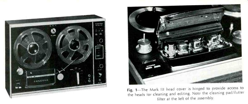
Fig. 1--The Mark Ill head cover is hinged to provide access to the heads for cleaning and editing. Note the cleaning pad/flutter filter at the left of the assembly.
MANUFACTURER'S SPECIFICATIONS:
Speeds: 7 1/2, 3 3/4, 1 7/8 ips; Motor: Hysteresis synchronous; Speed accuracy: 99.7% with line-voltage variation from 100 to 128 V; Frequency Response: 7 1/2 ips, 20-23,000 Hz; 3 3/4 ips, 20-14,000 Hz; Wow and flutter: 7 1/2 ips, under 0.09%; 3 3/4 ips, under 0.12%; Signal-to-Noise Ratio: 52 dB; Bias frequency: 200 kHz; Reel Capacity: 7 in.; Dimensions: 18 1/2" wide, 13" high, 6 5/8" (over knobs and head cover). Weight: 25 3/4 lbs. Price: Under $260.00.
Replete with practically everything the recordist could want in a tape machine, (except power amplifiers and speakers) the new Concord Mark III offers three speeds, low wow/flutter, sound-on-sound facility, echo facility, tape or source monitoring, and dynamic muting. This is the first machine we have examined which incorporates an integrated circuit in the electronic lineup, which serves mainly to reduce the total number of transistors as separate elements. Even so, there are 13 discrete transistors, the two integrated circuits,. and 15 diodes in the circuit, not to mention the four additional diodes in each of the integrated circuits, as well as five transistors.
Each of the record circuits requires four transistors, while each playback circuit employs two plus the integrated circuit. The metering circuits require one diode for each channel, and four are used in the power supply. The remainder of the diodes are in the dynamic-range-expansion circuit, as are two additional transistors; the final transistor is used as a voltage regulator.
Basically the circuitry is fairly conventional. The microphone input jack in each channel feeds the base of the first transistor in the record circuit, with the auxiliary inputs feeding the same points through the open-circuiting microphone input jack and a resistor to make up for the additional sensitivity of the mic inputs. A slight amount of bass boost is provided by feedback around the first pair of transistors, while the high-frequency boost is provided by bypassing the output emitter with a resonant circuit which is switched to provide compensation for the three speeds.
In the playback circuit, which operates even during recording to provide for tape monitoring, the playback head feeds the integrated circuit directly, with playback equalization being provided by feedback to one base of a differential amplifier in the IC. The turnover point is switched for the three speeds. The IC is followed by one transistor which feeds the line outputs, and the headphone monitoring circuit requires another transistor which drives a transformer to furnish the low impedance for the usual stereo headphones, while the record-level meter is driven from the emitter of the transistor directly through a calibrating resistor and a diode. The meter indicates record level when the monitor switch is in the SOURCE position, although it also indicates the output from the playback head either during playback or while recording if the monitor switch is in the TAPE position.
The "dynamic range expander" circuit takes its input from the line-output jacks, amplifies it, and applies it to a pair of diodes which offer a high impedance whenever there is any signal present, and thus effectively disconnect a 1-µF capacitor from shunting the output. In the absence of signal, the diodes are biased positively and the capacitor shunts the output circuits, reducing the tape hiss appreciably. This circuit employs eight diodes and two transistors, but is relatively simple, and effective enough to reduce hiss by about 4 dB, which is sufficient to be an improvement to the ear.
The physical appearance of the recorder is fairly conventional in that there are two reel hubs, the head assembly, the capstan and idler, and the control knob, which is of the bar type.
It has five operating positions: to the left of the STOP position is the REWIND function, and to the right are the PLAY/RECORD position, the cuE function, and FAST FORWARD. The record buttons are actually two levers at the lower left corner of the panel, with the digital counter directly above them.
One desirable device is the guide roller and tape-tension arm at the left of the head cover. The roller tends to smooth out the tape tension as the tape is drawn from the supply reel, and is aided by the tape-tension arm.
A similar tension arm is located at the right of the capstan, so that the effect of warped reels is minimized, and even sticky tape does not affect the tape motion.
At the right of the panel is the amplifier control section, which is mounted directly on the panel. At the top are three switches: one turns on or off the dynamic muting circuit, and the other two select tape or source monitoring on the two channels individually. Below these switches is the left-channel record-level control, and under it is the dual VU meter, with illuminated indicators to show when the machine is recording. Next is the right-channel record-level control,, and below it is the power switch-a push-push button-and the headphone jack.
At the lower right of the recorder panel are the two microphone jacks. A knob at the top of the panel operates the speed-change function-mechanically for the tape transport, and electrically to change equalization.
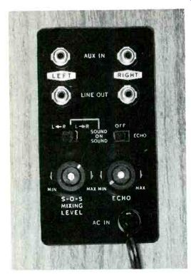
Fig. 2-Input and output connections are made in the recessed panel on the right side of the case, and additional switches and controls for sound-on-sound and echo are on the same panel.
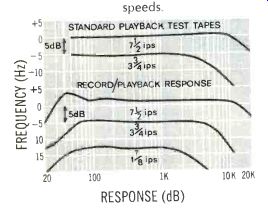
Fig. 3-Frequency-response curves: The two upper curves are response from standard tapes, while the three lover curves show record/playback responses at all three speeds.
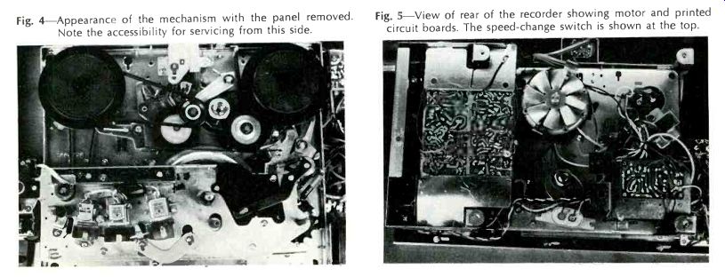
Fig. 4-Appearance of the mechanism with the panel removed. Note the accessibility
for servicing from this side.
Fig. 5-View of rear of the recorder showing motor and printed circuit boards. The speed-change switch is shown at the top.
The head cover is hinged to provide easy access to the heads for cleaning and editing, as is shown in Fig. 1. The tape path is first past a tape cleaner--a cylinder of felt over which the tape passes, and which also serves as a flutter filter. It is encased in a metal housing which exposes only a portion of the cylinder, allowing it to be turned to a fresh position when it gets soiled.
Next the tape passes an automatic shutoff lever, then the three heads, and out to the capstan. During play or record, hinged covers are raised in front of the heads to provide shielding and to carry the pressure pads. A pilot light at the top of the head cover indicates when power is on.
At the right side of the case is a cutout exposing a panel, Fig. 2, which accommodates the auxiliary input jacks, the line output jacks, and the SOUND-ON-SOUND and ECHO switches, as well as the level controls for these functions. The power cord also enters at this panel.
Performance
Figure 3 shows the frequency-response of the Mark III on a standard test tape for 7 1/2 and 3 3/4 ips, as well as the record/playback responses for all three speeds. Bias frequency measured 190 kHz, which is certainly high enough to avoid the fifth harmonic of the highest frequency likely to be recorded. This has long been the standard criterion, although we have measured a number of machines in the past year which have been over 100 kHz, so there seems to be a trend in the direction of higher and higher bias frequencies.
Wow and flutter measured .075% at 7 1/2 ips, 0.18 at 3%, and 0.24 at 1 7/8, all of which are excellent. THD measured 1.5% at "0" recording level, while the 3% point was found to be at a +6 level. S/N measured 46.5 dB below the 3% distortion level, but this increased to 50.5 with the dynamic range expansion circuit activated. A microphone input of 0.8 mV was sufficient for a "0" recording level, and an auxiliary input of 0.168 V provided the same level. The measured output level was 0.68 V for the "0" recorded level signal. Microphone input impedance is relatively high, measuring better than 10,000 ohms, while the auxiliary input is 100 k ohms. Channel separation was a good 35 dB at 1 kHz, which was also measured from track to track between adjacent recordings-also good.
Operation
The Mark III is easy to operate, easy to thread, and easy to listen to. The dynamic muting circuit helps the tape-hiss problem appreciably. It is surprising what only 4 dB can do, particularly when the hiss is already fairly low. The echo function works as would be expected, although this type of action always gives a slight repetitive sound which is easily recognizable as the result of any tape re-entry system.. It is most satisfactory at 7 1/2 ips, and unless a special effect is desired, it should not be employed at the two lower speeds. The sound-on-sound function operates equally well on all three speeds with adequate control of level and a simple selection of R to L or L to R by means of a single slide switch.
The machine starts quickly, and the tape-tension arms effectively eliminate any "burble" as the tape starts to roll.
For editing purposes, the accurately marked head-gap positions-arrows on top of the head assembly-are a great help in locating the exact gap locations. The pressure-sintered ferrite heads are claimed to be non-magnetizable--a problem that exists with usual laminated iron heads. In any case, we could notice no increase in hiss over the many hours we used the machine in testing and listening.
A handsome dust cover of transparent plastic of a slightly smoky hue covers the mechanism when desired, leaving the amplifier controls accessible to the user. This cover helps keep dust off the tape and out of the mechanism, both while playing and when not in use.
For an additional $70.00, the user can obtain all the facilities of the Mark III plus automatic reverse play in the Mark IV. To users, who like extra-long play time, the extra cost would be well worthwhile. Either unit would make a fine addition to a hi-fi system which lacks a tape deck.
--------------
Kenwood "Supreme 1" Multi-Channel Integrated Stereo Amplifier
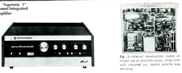
Fig. 2--Internal construction makes efficient use of available space, while vertically mounted p.c. boards provide easy servicing.
MANUFACTURER'S SPECIFICATIONS:
MAIN AMPLIFIER SECTION--Power Output (rms)/ channel: Low-Range Amplifier, 33 watts; Mid-Range Amplifier, 23 watts; High-Range Amplifier, 15 watts. Music Power: Low-Range Amplifier, 80 watts; Mid-Range Amplifier, 50 watts; High-Range Amplifier, 35 watts. All referenced to 0.5% THD. Frequency Response: Low-Range Amplifier, 10-100,000 Hz, 1 ±1 dB; Mid-Range Amplifier, 100-100,000 Hz, ±1 dB; High-Range Amplifier, 1000-100,000 Hz, ±1 dB. Signal-to-Noise Ratio: 90 dB. IM Distortion: 0.2% at 3 dB below rated output.
CONTROL AMPLIFIER SECTION--Input Sensitivity: Phono 1, 2 mV; Phono 2 (low-level setting), 0.1 mV; Tuner, 200 mV; AUX; 200 mV; Tape Head, 2 mV; MIC, 2 mV; Tape Play, 200 mV. Bass Control: ±12 dB at 100 Hz. Treble Control: ±12 dB at 10,000 Hz (with selectable cross-over frequencies of 2000 and 5000 Hz). Equalization: RIAA 20-20,000 Hz ±1 dB, NAB 20-20,000 Hz-±1 dB. Signal-to-Noise Ratio: Phono, 60 dB; Phono (Low), 50 dB; Tape Head, 60 dB; Tuner, 90 dB: AUX 90 dB. Frequency Response: 20-50,000 Hz ±1 dB.
FILTER SECTION-Low Filter: 12 dB/ octave with 40and 80-Hz cut-off points. High Filter: 12 dB/octave with 6-kHz and 9-kHz cut-off points. Cross-over Filters: Low Crossover: 12 dB/octave at 400 or 800 Hz. High Crossover; 12 dB/octave at 2500 or 5000 Hz.
GENERAL-Dimensions: 16 3/4" x 6 6/32" x 12". Weight 36.3 Lbs. Price: $695.00.
Proponents of electronic cross-over amplifiers should have a field-day with the new Kenwood SUPREME 1. While the idea of dividing the various frequency ranges electronically instead of by means of L-C passive filters positioned after amplification is not new, this new unit from Kenwood incorporates so many flexible features that it may, perhaps, encourage heretofore trepidations audiophiles to try this approach to feeding woofers, mid-ranges, and tweeters.
To begin with, the SUPREME 1 is the first integrated amplifier we have tested that actually includes six powerful amplifiers on one chassis (three for each channel) . What's more, just in case you are not ready to discard the inductance-capacitance crossover networks present in your existing speaker systems, the so-called "low range" pair of amplifiers can be used as wide-range amplifiers simply by setting the "low" crossover switch to "flat." This first pair of amplifiers boasts 33 watts per channel RMS and, with its capability to act as a wide-range (flat-response) amplifier, could actually be used as a conventional stereo amplifier all by itself. Taking it one step further, the second crossover switch, besides providing mid-high crossover frequencies of 2500 and 5000 Hz also has a FLAT position, so that owners of two-way speaker systems (as opposed to three-way) can also use these amplifiers to advantage.
A front view of the SUPREME 1 does not in any way disclose its unique multi-amplifier construction. The attractive silver-banded and dark olive front panel, shown in Fig. 1, is equipped with modern, metal-turned controls, push buttons, and levers, all of which combine to denote extremely flexible but uncluttered design. The six pushbuttons at the upper left select signal sources while the two, two-position levers directly below are power and tape-monitor switches. At the lower right area below the selector push buttons is a five-position mode switch which includes such long-abandoned positions as mono, reverse, stereo, left only (to both speakers) and right only. The volume and balance controls are concentrically mounted, but use huge front and rear knurled knobs. It is obvious that these are intended to be (and, in fact, are) the most-often-used controls. Separate bass controls (for each channel) and treble controls occupy the right area of the panel, each calibrated in dB of boost or attenuation. Directly below the bass controls are the low-filter switch (with cut-off settings at 80 and 40 Hz) and a tone-defeat switch which eliminates the bass control action entirely. Similarly, below the treble controls, are the hi-filter switch with cut-off selectable at 6 or 9 kHz and a treble cross-over switch enabling treble action to start at either 2 or 5 kHz or permitting defeat of the treble control altogether.
The lower brushed aluminum band of the panel turns out to be a hinged door which, when swung downward, discloses less-often-used controls, such as a phono input switch (for lowor high-gain operation of the second phono input), a phase reversal switch, (How long since we've seen that, even on expensive equipment?), six tiny level controls for balancing low-, mid-and high-frequency speakers of each channel (set only once, at installation, or when changing speaker complement), and microphone input jacks and tape playback jacks which eliminate the need for getting at the rear panel every time you want to play a tape through this amplifier.
In addition to the usual imput jacks and convenience outlets located on the rear panel of this amplifier, there are six sets of output terminals (binding post type). The crossover frequency switches are also back here, since they will be adjusted only once. Recorder output jacks as well as preamp output jacks (for those wishing to drive other stereo amplifiers), a line fuse and a DIN multiple tape recorder socket (standard with many foreign makes of tape recorders) complete the rear panel layout.
In case you're wondering how six power amplifiers and two professional preamplifiers can be crammed into the small confines of this unit, Fig. 2 discloses that every cubic inch of inner chassis surface and volume is most efficiently and neatly used. Vertically mounted p.c. boards abound and highest-quality components are in evidence. Heat sinking of output circuits was found to be quite adequate and extended use of the instrument at high power levels (even under instrument and continuous testing) did not raise the temperature of the case by more than a few degrees.
Electrical Measurements
In general, we found the Kenwood SUPREME 1 to be conservatively rated in just about every specification. For example, individual power amplifier ratings measured 35, 25 and 15 watts for low, medium and high channels of each stereo channel before total harmonic distortion (THD) of 0.5% was reached. Results are shown in Fig. 3.
Tone-control action was balanced and symmetrical, as shown in Fig. 4 and, for our listening tastes, we preferred the 5-kHz crossover for the treble control because it enabled us to add just a bit of emphasis at the extreme highs without "lifting" the middles. A plot of the highand low-filter responses is shown in Fig. 5 and, unlike most "rumble" and "scratch" filters, these "12 dB per octave" circuits are legitimate and useful, enabling the user to eliminate "scratch" on older records without sacrificing musical content.
The crossover response for each position of both the low-mid and mid-high crossover circuits is shown in Fig. 6, and is seen to conform to published specifications. As will be noted later, however, using the six amplifiers to drive two sets of woofers, midrange and tweeters is not all that easy.
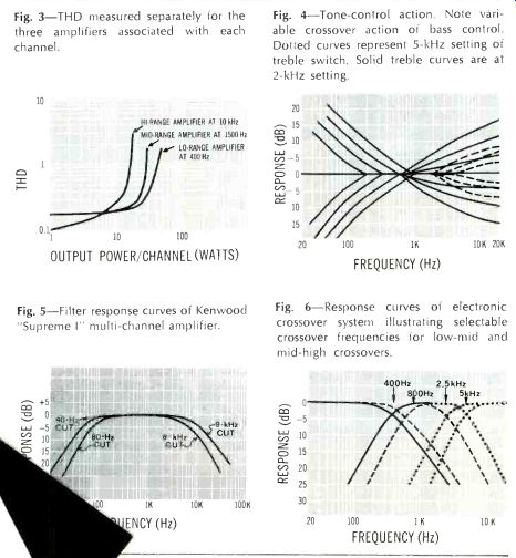
Fig. 3-THD measured separately for the three amplifiers associated with each
channel.
Fig. 4-Tone-control action. Note variable crossover action of bass control. Dotted curves represent 5-kHz setting o treble switch. Solid treble curves are a 2-kHz setting.
Fig. 5-Filter response curves of Kenwood "Supreme I" multi-channel amplifier.
Fig. 6-Response curves of electronic crossover system illustrating selectable crossover frequencies for low-mid and mid-high crossovers.
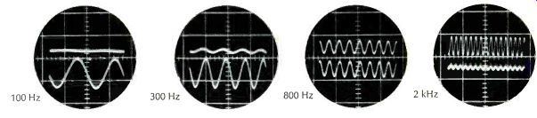
Fig. 7--Upper trace represents output of midrange amplifier; lower trace is
output of bass amplifier. Frequencies applied as noted.
Intermodulation (IM) distortion in a multi-channel amplifier has relatively little meaning, since the two frequencies used in measuring this form of distortion will actually be fed to two different amplifiers, and resultant IM should be negligible. Our listening tests disclosed that this was so-for we could detect no evidence of IM and, when attempting to overload the amplifiers, THD seemed to appear long before we could detect any evidence of IM distortion (the reverse is usually true in conventional wide-range single amplifiers). Power-bandwidth, that much respected IHF specification, also has little significance in a multi-channel amplifier of this type, since the manufacturer readily admits that the mid-and high-range amplifiers have less power-handling capacity than the low-range sections, so no attempt was made to derive a power response curve for this equipment.. Listening Tests Since using the Kenwood SUPREME 1 involved disconnecting all crossover networks, we could not use "sealed" air-suspension type speaker systems.
We therefore employed a venerable but well-respected pair of infinite-baffle, three-way systems, and proceeded to tear out the coils and capacitors from each one. Following connection instructions, and using the six-wire cables supplied by Kenwood for each system, we turned the amplifier on, not knowing what to expect.
Our immediate disappointment was totally shattering! The highs were too penetrating, while the mid-range tones seemed like we had a double "presence control" in the circuit. Only then did we open the hinged "trap door" and attack the six little level controls put there for just this kind of situation.
For reasons which are not readily apparent, we 'found, after about a half hour of careful adjustment, that the mid-range controls wanted to be at about 1 o'clock, while the high-range controls settled in at about 12 o'clock--all the while the low-range controls were fully clockwise! Admittedly, electrical measurements had disclosed that output power was balanced for all frequency segments when these controls were all set identically, but evidently the efficiencies of the woofer, midrange and tweeter elements used were nowhere near identical, and perhaps built-in losses in the crossover networks no longer present had served to compensate for these differences before. After careful adjustment of these level controls, however, we must confess that the balance was as smooth over the entire frequency spectrum as anything we had ever heard. It should have been-since we were really able to custom-tailor it to our own individual taste-something you just can't do with tone controls alone.
We were so intrigued with the electronic crossover principle that we decided to take a set of dual-trace scope photos to illustrate just what happens between the low-range and mid-range amplifiers as one sweeps from low to higher frequencies. The results are shown in Fig. 7, and the captions are self explanatory. Note, that at 800 Hz (the crossover point we selected), the amplitudes of output in low and midrange channels are just about equal, which is as it should be.
Summing up, the Kenwood SUPREME 1 will enable the patient and discriminating user to "shape" tonal response to a degree not possible with conventional wide-range amplifiers. It has adequate power reserve, excellent control flexibility, and is most attractive in appearance and in price. If you've already selected a "sealed" speaker system that you don't want to break into, this unit is obviously not for you. If, however, you plan to build up your own speaker arrangements, buying either "ready made" but accessible multi-element speakers or purchasing your own woofer, midrange, and tweeter systems, piecemeal less crossover networks, the SUPREME 1 will be a most fitting way to supply them with precisely balanced quantities of clean-sounding, distortion-free audio power.
--------------------
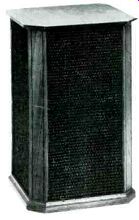
Scott Model Q-100 "Quadrant" Speaker System
MANUFACTURER'S SPECIFICATIONS: Impedance: 6-8 ohms. Dimensions: 14 1/4" x 14 1/4" x 22" high. Weight: 37 lbs. Price: $149.95.
Scott's "Quadrant" loudspeaker system offers an unconventional solution to the problem of sound dispersion (or, rather, the lack of it).
Ideally, it would be nice for a speaker to radiate sound omni-directionally from a point source.
What the Scott Model Q-100 does is to radiate high frequencies from all of its four sides, and lows from two sides.
The result is nearly omni-directional sound radiating from these units, with very pleasing results.
The speaker system is a small, walnut, floor-standing console with dark gold and brown grille-cloth panels on four sides. The panels are removable, exposing the six speaker complement.
A 3-in. cone-type tweeter is built into each of the sides, near the top of the enclosure, while an 8-in. acoustic suspension woofer is built into each of two opposite sides near the bottom. The speakers are all connected in phase, and the crossover network which separates the 8-inchers from the tweeters [...]
------------------
(Audio magazine, 11/1969)
Also see:
ABZ's of Stereo FM--Modern Switching-Circuit Decoder
How Disc Masters Are Made Today
H. H. Scott, Inc. Perfectune (ad)
Tape Transport Maintenance--Part 3
= = = =