Dynaco MARK III MICROFARADS MULTIPLIED
I HAVE COMPLETED a simple and inexpensive modification to my pair of Dyna Mark IIIs which has improved the overall sound substantially. The modification derives from some experiments I did with an unmodified Mark III after becoming dissatisfied with the sound when driving full-range electrostatics (KLH Nines). I took one into my basement laboratory, made sure the output tubes were healthy and the amp was biased correctly, and looked at the output, power amp B+, and driver B+ with a variety of signals into a 16 Ohm load.
I discovered the power supply was collapsing at very low frequencies when driven hard; if driven with a 20Hz square wave the power amp B+ began to collapse after about 90 degrees. At the same time, the driver B+ also collapsed as the output stage stole power from the driver filter capacitors. I also noticed the Mark III rings about a half cycle at about 50kHz; this is not important, but the fact that the amplitude of ringing was asymmetric indicated the phase inverter might be a problem. I did not attempt to fix the driver; I did try to fix the power supply.
The modification consists of adding about 500uF of capacitance on either side of the B+ filter choke, replacing the dual 20 uF unit used there. In addition, the two 20uF capacitors used to isolate the driver were replaced with 250 uF each, and a decoupling diode added between the driver B+ and the output stage (a surplus 600 PIV 1A diode was used.) The capacitors are made up, as Fig. 1 shows, from 500 uF 275WVDC units obtained from Fair Radio Sales for $1 each. Similar devices, in better condition, are available from other dealers. (Surplus items are subject to prior sale, of course.- Ed.) Two placed in series, using 220K 1W balancing resistors yield 250 uF at 550WVDC (660 surge). A total of 12 are used for each amplifier.
The capacitors from Fair Radio Sales, although dirty and old, have all tested out as good (both capacitance and power factor). My two amps have now run for months without failure. The capacitors come from two different manufacturers, however, with different leakage and mounting specifications. Even with 220k balancing resistors, do not attempt to mix different brands in series.
The capacitors were mounted upside down on a 9" x 7" x 2" chassis, using two rubber grommets (1/4'' I.D., 3/8 " O.D., a 1/4'' flat washer (try them for size first; not all will fit), a 10-32 solder lug, a 10-32 flat washer, and a 10-32 x 5' screw for each terminal. (Fair Radio Sales does not supply screws.) (Mounting rings are a safer, easier, although more expensive alternative. -Ed.) The chassis is drilled for 24 holes; grommets are inserted in each pair of holes, and then the terminals are pushed through the grommets. Place another grommet around each terminal to pull the capacitor down snugly onto the grommet mounted on the chassis. The washer goes next, followed by the solder lug, the 10-32 washer, and the screw.
There are three important safety considerations: the need for insulation on the outside of the capacitors, the need for care in inserting the grommets, and the need for a check of the voltage drop across each capacitor in circuit.
The capacitor's case is connected to the (-) terminal; I therefore covered each one with electrical tape. It is best to first cut two small pieces, each about 1" longer than the width of the top, and cover it with them. Then, starting from the top and overlapping the two small pieces, wind electrical tape down the sides in a slow spiral.
This procedure, done before mounting, puts the end most likely to unravel at the bottom. The grommets mounted in the chassis must be free of holes; a hole may allow full B+ to appear on the chassis.
Carefully inspect all grommets after insertion for signs of tearing, and replace any that are suspect. Check each for isolation with your Ohmeter before interconnecting them.
Finally, after assembly, measure the voltage across each capacitor; it should be half the total across each series pair and well below 275V.
The new subchassis is mounted to the side of the Mark III nearest the rectifier tube, using four 6-32 nut and bolt assemblies. Punch a hole in the side of the Mark III and a matching hole with a grommet in the subchassis for the connecting wires. I used the old filter capacitor as tie point, which may lead to problems if it fails; I did not replace the SAR4, as I feel that some form of thermal delay is necessary to extend output tube life.
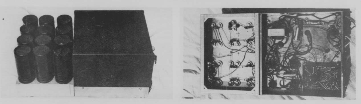
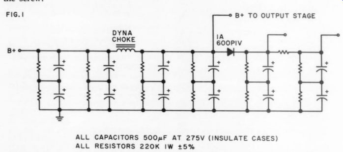
FIG. 1 ---- ALL CAPACITORS 500uF at 275V (INSULATE CASES) ALL RESISTORS
220K 1W +/- 5%.
One item that should be checked while the Mark III is apart is the pair of matched resistors used in the phase inverter-they are 47k, matched to plus / minus 1 percent. These resistors can drift in value through aging and should be checked or replaced.
The finished amplifier has a clean, well defined bass; the top end is very smooth.
The two Mark IIIs, as modified, drive my four electrostatic panels to high levels, indicating good clipping characteristics.
On the bench both amps now clip at 20Hz at the same power output as at 60Hz (60 Watts for one, 65 for the other). The muddiness of the original Mark III is gone.
Other more sophisticated modifications may be better ; this one works, and it costs about $20 per amp.
MICHAEL SQUIRES
Arlington VA 22205
ADD 78-RPM TO YOUR PHILIPS TURNTABLE
ROBERT SELLMAN WROTE in issue 4, 1977, p.46, that he had modified his Technics turntable to run at 78rpm. I made a similar modification to my Philips GA-212 with excellent results, and thought other readers might be interested.
The steps are as follows:
1. Center the 45 rpm fine speed control on the top panel.
2. Place a jumper around R575, the 1.8k-ohm 5 percent resistor in the location shown in Fig. 1.
3. Locate the trimpot R471 (with the turntable upside down, front facing toward you, it is just to the right of trimpot R470, which is attached to the speed control adjusted in the first step).
Adjust it so that the turntable runs at 78 rpm in what was formerly the 45 rpm mode.
Those who want to retain the 45 rpm speed may do so by installing a SPST switch, rather than a jumper, around R575. If juggling the trimpot settings fails to bring both speeds within the reach of the top panel control, use a DPDT switch and a second trimpot in the configuration shown in Fig. 2.
JOSHUA HILL
New York, NY 10025
MORE CAPS FOR PAS
AMATEURS WHO CONTEMPLATE modifying their PAS preamps (see issue 2, 1976, p.21) but who, for aesthetic or other reasons, don't want the outrigger / umbilical arrangement for additional capacitance should consider rearranging things inside the little PAS case.
By transposing the heater and B+ supplies, I was able to increase heater filtering to 11,000 and B+ to 900 uF. As the photographs show, I installed two 5,500 FP units in the spots vacated by the B+ multi-section and the rectifier tube. A pair of 50 PIV, 3A diodes (below the chassis) replace the sagged selenium. In place of the old heater supply I installed a five-lug terminal strip, a pair of 1000 PIV, 1A diodes, the dropping resistors, and four 2254F, 450V tubular units.
All grounding is to one point at the (-) end of the B+ capacitors. A slight increase in hum disappeared when I moved one of the 1000 PIV diodes another half inch or so away from the high level PC board. Follow Dyna's advice in checking for hum: turn it on, turn it up, and listen to the speakers. if you have more hiss than hum, you're o.k.
The capacitors, purchased through a Burstein-Applebee flyer sale, were relatively inexpensive. The new Magneplanars required to appreciate the improvement are another story.
J.D. CALDWELL
Arlington, VA 22204
DE-POP YOUR SOUNDCRAFTSMAN 20-12 THE SOUNDCRAFTSMAN 20-12
audio equalizer emits a loud ''pop'' when first switched into an operating audio system. This ''pop'' is not only annoying, it is also potentially damaging to loud speakers.
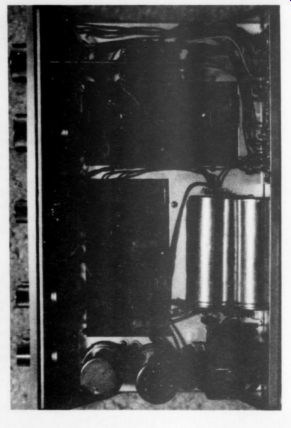
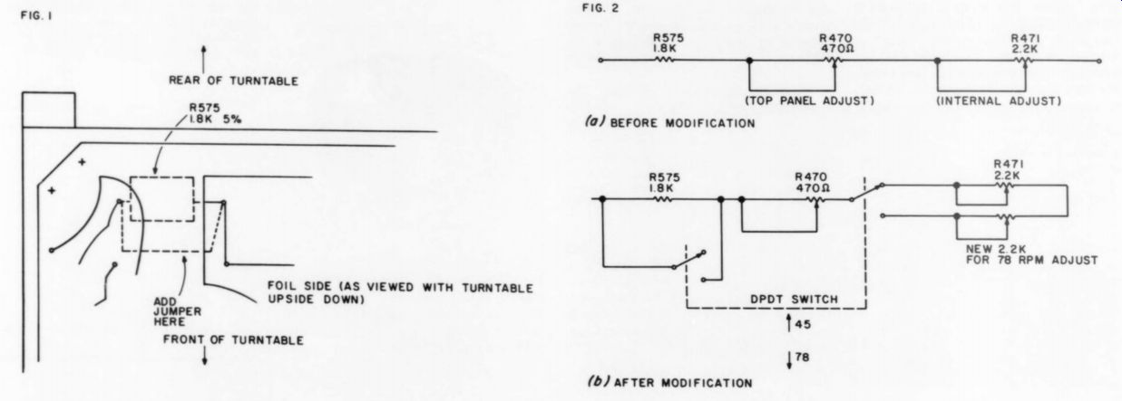
Fig. 1, 2
The Soundcraftsman operates from a single +32 volt regulated power supply, and hence must be capacitively coupled at both input and output. For those of us to Audio Aids whom this point is not obvious, the capacitors are needed to block the DC bias on the input and output devices from propagating out of the equalizer and into the rest of the audio chain. The capacitors block the DC and allow the audio signal (AC) information to pass into and out of the device.
In any case, the cause of the ''pop'' is that the outside end (the end not tied to the internal workings of the equalizer) on either the input or the output coupling capacitor drifts up to some intermediate DC voltage level while the device is not switched into the audio chain. When it is switched in, the guilty capacitor discharges suddenly and a loud spike propagates through the system to the speakers.
Inspection of the equalizer reveals that the output coupling capacitor is tied to ground via a load resistor and does not have any DC bias on its output. The coupling capacitor on the equalizer's input must then be the culprit. Inspection of the outside end of the input coupling capacitor with an oscilloscope shows that there is about 5 volts of DC present until the 1 megOhm input resistance of the scope drains it away. Unfortunately, the time constant (equal to RC or 1 megOhm times 4.7 microFarads equals about 5 seconds) is too long. If we used a 1 megOhm resistor, the discharge pulse would still propagate through the system. 100 kilOhms was arbitrarily selected as a compromise between reasonable decay time constant and audio fidelity, as a lower value resistor would start to roll off the low end of the equalizer's response. (The cutoff frequency or 3dB down point is at 2 RC and is equal to 0.3Hz.) So having diagnosed the problem, and having prescribed a solution, how do we go about implementing it? Remove the four feet on the underside of the simulated walnut cabinet, being very careful not to snag the sharp corners of the wrong panel on the easily damaged vinyl. Remove the top and bottom covers of the metal chassis and trace the green and black twisted wire pairs from the equalizer in / out rocker switch.
One pair is a plain green wire with a black wire and the other is a white-striped green wire with a black wire. Each of these wire pairs goes to a pair of wire wrap posts on their respective circuit boards. Take a pair of 100kOhm (brn / blk / yel) resistors and bend them into a U, Japanese transistor radio style. (See illustration.) Fold a small flat loop in the end of each of the leads so that the loop will just encircle the end of the wire wrap post and its solder puddle. Now solder in the resistors, one end to the green wire's post and one end to the black wire's post. Note that you are to solder the resistors to the foil side of the board and not to the wire wrap post themselves.
The cure to the ''pop'' having been accomplished, there is one small job to do before you reassemble the unit. Rub down the top and bottom plates to the chassis on both sides with a clean rag dampened with a good quality light oil. (If the rag drips when it is wrung out, there's too much oil in it.) The Soundcraftsman chassis is made of steel with a very light anti-rust coating on it. Finger acids will etch through this coating and expose the steel to rust. All you want to do with the oil-dampened rag is wipe off perspiration and body oils and restore the corrosion-resistant surface.
All that is left to do is to replace the top and bottom covers, restore the equalizer to its cabinet and hook it up for the test.
The annoying ''pop'' should now be significantly muted or gone altogether.
Unfortunately, you have also voided your warranty.
--------------
D.W. THOMPSON
Melbourne, FL 32901
COAX SOLDERING TRICK
SOLDERING coaxial cable after one has stripped the outer shield is difficult and tricky. The kind with foamy center insulation is worse. One day while in EDI (Electronic Distributors Inc.) one of TAA 's regular advertisers, I saw a Clauss Antiwicking tweezer, 20 gauge. I use it as a heat sink around the central core in sulation and its conductor. It works beautifully.
JOHN R. WINN
Chicago, IL 60629
CASSETTE SPEED SAGS
HARMAN-KARDON'S HK-1000 cassette deck quite often has a noticeable speed drift. We have seen instances where speed at the end of a tape was 3 percent or more slower than at the beginning.
HK's motor servo system is an old design using a two-terminal motor with no tachometer, and no doubt was carefully tweaked to track the motor's thermal coefficient of resistance. Production tolerances sometimes destroy such a Audio Aids delicate balance, however, and one may have to make adjustments. In a recent case we cut the downward speed drift in half by relocating K503 (the 2SA672 transistor near the edge of the servo printed circuit assembly) inside the pass transistor heatsink and spacing the entire assembly away from the chassis with nylon washers to let it run warmer. You could probably do even better if you have time to play with the circuit values.
Some of these circuits (Panasonic Fisher) use a copper resistor, and at least one (Lear Jet A239) actually had the copper resistance coil wound inside the motor for precise thermal tracking.
MIKE HARDWICK
Westronix Salem, OR 97303
ESA-3 HIGH VOLTAGE
IF YOU ARE LOOKING for a relatively small but quite excellent direct coupled amplifier to drive your .062"' diaphragm to-stator spaced electrostatics, you will find David Hermeyer's ESA-3 can easily be modified to operate at a B+ of 2200VDC. Not having sufficient electronics background to modify the original ESA-3 circuit without some assistance, I asked Dave how to operate his new amplifier at higher voltages. I thank him here, not only for the modification details but also for his patience which I'm sure I stretched a bit with a multitude of questions.
The power supplies remain unchanged except for the B+ supply. For a B+ of 2200VDC, I would recommend a B+ transformer of 1700VAC at 250mA. The DC voltage at the output of this supply will depend not only on the transformer's voltage rating but also on its current rating: the higher the current rating, the less the B will drop under load. I used a transformer rated at 1800VAC at 400mA which I removed from an old Heathkit Apache amateur radio transceiver.
When 1 first turned on the amplifier, this rather hefty transformer produced a B+ of approximately 2500VDC under load. A 6.3VAC at 6A filament transformer connected in series with the B+ transformer primary (see TAA 1/77, p. 38) brought the B+ down to just above 2200VDC. Each leg of the full wave bridge rectifier should contain six 2.5A 1000 PIV diodes instead of the original three diodes per leg. Parallel each diode with a 470K 1W resistor and a .01 uF 1KV ceramic capacitor. These resistors and capacitors will equalize the diodes' back resistance and offer protection against voltage transients.
The filter capacitor remains at 15 uF but with a voltage rating of 2500V or higher.
If you wonder about the effects of using a more complex filter in the B+ supply, I can assure you the simple, single 15 uF oil filled capacitor offers excellent performance with minimal weight and size.
Using filter chokes and larger capacitors will offer no audible performance improvement.
If the input signal requirement is a bit high for your system (6 volts peak-to-peak in the original ESA-3), substitute 1.5k metal film resistors for the 3k resistors which appear on either side of the 100 Ohm balance pot, reducing the input requirement to approximately 1.1VRMS.
With this resistance change my modified PAS has no trouble driving the amplifier through my original IC electronic Crossovers.
You can calculate the power dissipation of each tube and each plate resistor using the formula: (B / 2)2 /R, where R is the value of the plate resistor in Ohms. Select the plate resistors so that the tube cannot operate outside it's 35 Watts maximum power dissipation rating. As the plate resistor's value increases, the full power bandwidth will decrease. You'll find a 40k plate resistor will allow excellent amplifier performance while holding the power dissipation of the tube and plate resistor to a comfortable 30.25 Watts. The plate resistors get quite hot during operation and should be rated at 100 Watts or higher.
Increase the feedback resistor chain value in direct proportion to the increase in B+. Simply multiply the original feedback chain value (20 x 50k) by the ratio of the new B value to the original value of 1200VDC. For a B of 2200VDC, the multiplication factor becomes 2200 / 1200 1.83 by 20 x 50k.
This results in a feedback resistor chain consisting of 20 91.5k resistors in series.
This, in turn, is equivalent to 24 75k resistors and one 30k resistor, all in series, for each feedback chain. The 1pF capacitor in parallel with each feedback chain does not change in value; however, you should increase its voltage rating to 3kV. The 10pF capacitor between each tube plate and ground should have a voltage rating of 3kV or higher.
The modified ESA-3 will drive your electrostatics every bit as well and in some ways better than Dave Hermeyer's excellent ESL-2 amplifier. As a side benefit, you will achieve a 50 percent reduction in weight and a two-thirds reduction in power consumption. For those of you seriously considering construction of this high voltage amplifier, I present a few recommendations and observations.
While this isn't absolutely required, I highly recommend that you mount all four 8068 tubes in a chimney with a cooling fan below. If you object to the noise of a fan, shop around: you may be quite surprised at the low noise level of a good whisper fan. A cooling fan and a tube filament voltage of 6.0VAC will not only greatly extend the tubes' life, but will stabilize the amplifier, which means less overall downtime.
For the balance and offset pots I used multi-turn trimmers. If you elect to use these to make adjustments easier use a cermet trimmer rather than a wire-wound type as the inductance of the wire-wound pot could cause phase shift with oscillation problems.
Each power supply in the amplifier should be independently fused with a fast acting glass fuse. I have six fuses in my amplifier, each paralleled with a neon lamp mounted on the amp's face plate.
These lamps form a ' 'fault locator panel'' which immediately indentifies the malfunctioning power supply should a problem develop.
When I first completed the amplifier, I was plagued by a 1.4MHz oscillation at the right channel output. After a frustrating search I stumbled upon the culprit. The PC boards in my modified amp are basically the same as those in the original ESA-3. A length of high voltage test prod wire runs from the top of each feedback resistor chain through a rubber grommet-lined hole in the 8068 tube chimney to the respective tube plate cap. If the section of test prod wire between the feedback PC board and the hole in the chimney is allowed to rest against and run along the tube chimney, oscillation will occur. By simply moving these wires away from the tubes, you'll eliminate the oscillation. My system is virtually noise free, and that includes 60 / 120Hz hum.
Should you experience oscillation problems, try rerouting the wires connecting the feedback resistor chain to the tube plate cap.
Regardless of what you are using to drive the amplifier, you must ensure it has no DC at its output. For an integrated circuit device, such as an electronic crossover, you can easily eliminate any DC offset voltage at the output by using the applicable output offset voltage compensation circuit specified by the IC manufacturer. A simpler solution uses a blocking capacitor between the device's output and the input to the amplifier.
Anything between 0.1 uF and 1.0 uF will produce satisfactory results.
To add a further measure of stability and longevity to the amplifier, I added a system of delay turn-on circuits.
Positioning the on / off switch to ''on"' applies power to the tube filaments and the whisper fan. Approximately 45 seconds later an Amperite delay relay activates a 120VAC 15A power relay which applies power to the remaining supplies. A 30 Ohm resistor is in series with the primary of the B+ transformer for surge current reduction. Five seconds after the first 120VAC power relay applies power to the amp supplies, a second Amperite delay relay activates another 120VAC 15A relay which shunts the 30 Ohm surge resistor. Finally, the diaphragm bias supply is activated by the turn-on time delay circuit which appears in the original ESA-3 construction article. A .01 uF ceramic capacitor appears across each switch and relay contact to help reduce contact pitting due to arcing.
I have cycled the amp on and off hundreds of times during testing, and driven it by both solid state and tube equipment with no problems in either case. I have thus far logged many listening hours using the modified ESA-3 with no downtime whatsoever. An original low mass, unipivot, damped tonearm / Decca MK VI plum combination; modified PAS which combines the best of D. Vorhis, Audio Dimensions, and ARC; a ten octave ''Octalizer'' equalizer with additional equalization at 30Hz; original IC electronic crossovers featuring plug-in filter cards; and a Williamson 20 / 20, with Wheals regulated supply, driving a 224HS Hartley in a 20 cu. ft. enclosure, round out my system, which is very accurate, requiring only the finest of signal sources.
I shall be most interested to hear of the results of anyone who undertakes construction of this modified amplifier, or any other electrostatic projects.
MICHAEL K. MORITKO
3711 West St. Patrick Street, Rapid City, SD 57701
TESTING HIGH POWER OUTPUT TUBES
TO THOSE USING the Hermeyer or Sanders Electrostatic amps: I found a way to test 813's (and I guess other power tubes) for gassiness by using an ohmmeter. Set the meter to 1000Mohm full scale and measure resistance between grids and cathode. Bad tubes will have measureable resistance (i.e. less than 1000Mohm). One bad tube had 4Mohm on one plate and 18Mohm on another. By the way, perform these tests with the tubes removed from the chassis.
The first sign of a bad tube is that the voltage on one channel's pair of tubes will be more than 30 volts lower than on the other. Because of the large amount of interaction between the tubes, it is difficult to isolate the bad tube in a functioning amplifier.
DAVID WHITE
Nashua, NH 03060
--------
YOU CAN HELP
AUDIO AMATEURS are rare birds. We search far and wide by many means to find new subscribers. You can help The Audio Amateur grow by helping us find newcomers to the audio craft, or seasoned practitioners who may not have heard of TAA. You probably know some of these rare birds-or likely candidates for the classification. Look among your friends for those with electronics-related interests such as computers or live music. Either send us their names, or tell us on a post card how many copies of our prospectus you can use. You'll help us grow-and our avocation to grow too. Thanks.
----------------
--------
Also see:
Audio Aids, by readers Squires, Hill, Caldwell, Thompson, Winn, Hardwick, Moritko, and White
Issues of Reliability and Validity in Subjective Audio Equipment Criticism, by Lawrence L. Greenhill, M.D. Scientific techniques which might improve listening tests.