INVERSION, RIAA and TIM
AFTER READING the correspondence of Walter Jung, Mark Davis, and Stanley Lipshitz in TAA and other journals, I would like to inject another opinion on the philosophy of effective design of audio circuitry. I feel we should not attempt to oversimplify the audio design process solely to generate a comfortable set of design rules which represent only part of the picture.
To be sure, phase inversion can be detected, and the difference can be quite striking with some loudspeakers and source material (e.g., flamenco music); but with material that is usually multimiked, a preferred position is often inversion, but I consider it only one of the many variables in the design equation.
I also feel the importance of super-accurate RIAA compensation is often overemphasized.
It is true that in a legitimate A-B test small differences can be heard, but each record reproduced through a phono system inherently contains virtually a magnitude greater deviation in response than the + 0.2dB everyone is striving for. I believe an accurate RIAA curve should be implemented, and I am pleased several designers have striven to define it accurately and design equations have been developed to make it easier to do properly. Yet I cannot understand how so much emphasis can be devoted to it, almost to the exclusion of every other factor.
Why, for example, is TIM so maligned when it can be demonstrated that virtually any moving coil cartridge can have enough ultrasonic output to evoke TIM in many of the current preamplifiers and power amplifiers? Are moving coil cartridges inconsequential to serious audio design? Besides TIM there are other neglected factors such as crosstalk, noise (especially when operating moving coil cartridges like the Denon directly into a preamplifier without an additional step-up device), and other factors too involved to list here.
Unfortunately, I have never found a piece of audio equipment at any level of design sophistication that I could say sounded completely accurate, ''like a straight wire with gain." 1 suspect it is difficult, if not impossible, to design a truly accurate preamplifier, because there is simply too much that we still do not understand.
Recently I designed two preamps with RIAA equalization (ref. Holman) within + 0.1dB of each other from 10-100kHz, each with slew rates greater than 100V/ us, and distortion unmeasurable on a Sound Technology (.001 percent at 3V output); yet each has identifiable sonic characteristics. In an A-B test between the units which have a somewhat different topology but the same frequency response, output (within 0.1dB), and absolute phase characteristics, there is a detectable sonic difference which has been verified by other professional listeners.
I do not wish to belabor the point any further, but I feel there is still much to understand about the design of audio equipment. To oversimplify the design criteria is an injustice to the efforts of designers continuing to research audio problems, and a disservice to the consumer who might glibly think that audio has reached an as yet unattained state of perfection.
JOHN J. CURL; Oakland, CA 94609
PAT-5-WJ-1 MODIFICATIONS & IMPROVEMENTS
SOME SAMPLES of the Signetics S534 IC op amp exhibit a parasitic instability (oscillation) under certain combinations of loading, signal level and circuit con figuration. Where the 5534 is used in the high level stage as IC301, it is possible under rather extreme conditions of use that the IC will oscillate.
Lest this sound like an alarmist warning, note that not all S534s are susceptible to this oscillation. The sensitivity to it varies from lot to lot. Also, whether or not it then occurs in a particular preamp depends on how the unit is operated with regard to loading and signal conditions. This oscillation appears to occur only on positive signal swings at about 2 volts level at a frequency between 30 and 40 megahertz. As such it is extremely difficult to observe on musical signals with anything other than a 100MHz scope, triggered just on the positive peaks. Nevertheless it can occur and will produce IM and grit in the reproduced sound. This will be apparent on the highest peak levels.
If you find this problem in your PAT-5-WJ -1, the cure is quite simple to apply to the 1C301 circuit. The step-by-step procedure is described in the accompanying box, and amounts to an alternate means of bandlimiting the S534 stage to 100kHz. If your PAT-5-WIJ -1 sounds good to you, chance are you do not have this problem and can safely leave it alone. However, it can be induced by certain unusual load conditions (for which the circuit was not originally designed) so this cautionary note is in order. In this view, see the Mogavero letter below, and the reply. We note that Texas Instruments is soon to be supplying the 5534 device which should increase its general availability (and perhaps modify the price structure?). [TI is not yet supplying 5534s to users as of Jan 23, 1979. When they do, Old Colony will announce availability. -Ed.] Preliminary tests of a few samples of their version of the amplifier show no signs of the above instability.
---------------
PAT-5-WJ -1 MODIFICATION FOR 5534 INSTABILITY
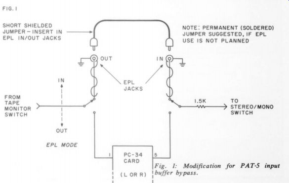
Fig. 1: Modification for PAT-5 input buffer bypass.
SHORT SHIELDED JUMPER = INSERT IN EPL IN/OUT JACKS ------- NOTE. PERMANENT (SOLDERED) JUMPER SUGGESTED, IF EPL USE IS NOT PLANNED
References: Figs. 3a and 3b of Issue 1/ 78, page 12.
(1) Remove C320 (150pF) from across 10k 1% resistor (*'C''319), on both modified PC-34 cards.
(2) Install two (new) 270pF polystyrene or mica caps from terminals of HFB switch as follows:
(a) from term 4, to same ground as Ca.
(b) from term 1, to same ground as Cb.
--------------
Readers may further improve the PAT-S's high level performance by following a tip provided by Robert Taylor of Taylor House ( Box 140, Denver NC 28037) who, we'd like to note, has a keen ear for good sound. He offers a number of modifications to audiophiles interested in the craft aspects as well as the good sound of top-notch gear.
The input stage, high level buffer of the PAT-5 is, as it turns out, not really necessary as an impedance translation device if the source impedance is sufficiently low. This condition is met in the PAT-5-WJ -1 when it is operating from the phono source, as its output impedance is only 100 ohms. Bypassing the Q301, Q302 stage eliminates it as a source of signal degradation and, when the remainder of the system is first rate, results in noticeable sound improvement.
The wiring changes necessary to accomplish this by-pass are rather simple and are shown in Fig. 1. The EPL input/ output jacks are used with an external jumper.
Functionally, pushing the EPL/ in switch bypasses the input stage. With it "out" the stage is in the circuit. Note that the two 1.5k resistors which had previously been on the PC34 card should be moved to the switch, as the schematic indicates. An easy way to preview this change without modifying your unit: simply place two jumpers from Tape Out to EPL/ in, push the EPL switch, and listen.
Our thanks to Robert Taylor supplying this information to Audio Amateur readers.
WALT JUNG
Contributing Editor
-----------------
CORRECTIONS
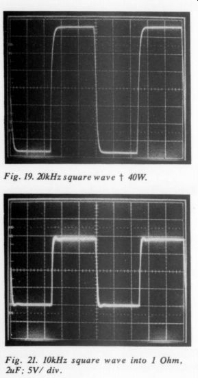
Fig. 19. Fig. 21. 10kHz square wave into 1 Ohm, 2uF; 5V/ div.
IN THE PASS A-40 amplifier article, Issue 4# 78, page 11, Figs. 19 and 21 were interchanged. Note the corrected pairing of CRT photos and captions below. Author Pass has also provided instructions for bridging the A40. Place a 10K ohm 1% resistor from the output of channel A to the base of Q2 on channel B, shorting the input to channel B.
Connect the speaker across the hot outputs of the two channels. In this mode the stereo amplifier, operating now as a mono device, will put out about 150 watts into 8 ohms. Note the diagram. -Ed.
DECCA RECORD CARE
Decca record care products, (mentioned in TAA 4/ 78, p. 29) distributed in North America by Rocelco, have a new address: 1669 Flint Rd., Downsview, Ont. Canada M3J 217. They also tell us they have a couple of new devices on hand. The Microbe attaches to the phono cartridge and not only cleverly protects the cartridge but then cleans grooves as the recording is played. They also have a new supertweeter "a la Levinson". You are welcome to write for information on these and other Decca products.-Ed.
PAT-5 REDO
The Jung/ White Pat-S modification (Issue 1/ 78, p.7; 2/ 78, p.49; 3/ 78, p.48) is really state of the art. I tried it on my Pat-4 and the sound is terrific! Here's what I did: On the pre-amp card JW-33 I tried the original design and the subsequent modification. However, I removed R2 and R3 and used IC1 as a voltage follower. R4 value changed to 750 Ohms for the same gain as the original design. If you want an additional 6dB of gain R4 should be 470 Ohms. Listening to each circuit I could not hear any difference since most sound energy is in the bass and midrange with little above 10kHz. (Or I could be losing my hearing.) I removed R8 since the feedback for the RIAA is taken from the output.
I eliminated the buffer circuit since IC-2 has a low output impedance (about one Ohm I suspect) which can more easily load the volume control (10K worst case) than the buffer circuit. The only drawback was that I could not switch to mono without causing subsonic disturbances unless the low filter was switched in. However, because the low end is solid and tight I removed the low filter and reused the loudness switch as a stereo-mono switch after the volume control. The 4P4T switch 1 installed for the low filter became a normal-bypass switch for the feedback-type tone controls on the PAT-4. "C" 319 (10K) on the high level circuit is the feedback resistor. However, on the PAT-4 this resistor is 4K7. Therefore, the tone control capacitors must be divided by 10/ 4.7 for the proper inflection point.
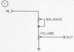
I connected the balance control to the "top" of the volume control with its wiper connected to the ground side (see Fig. 1). This removes the balance control as a load to ground but still gives about -10dB left or right attenuation.
C320 on the output stage was changed from 150pF to 22pFwhich gives me -3dB at about 600kHz rather than 100kHz. This is clearly audible. The sound is more spacious and less "sweet." 1 omitted R329 (221 Ohms) and "C" 3 (4k7) since they greatly limit IC301's ability to deliver current into a load (cables and input loads). I can also drive dynamic headphones directly from the output socket with great results.
Using a full wave bridge with the stock transformer you will get plus and minus 52 volts. This was too much of a drop for the dual tracking voltage regulator I was using.
However, the transformer has a split primary. Wired in series you will get plus and minus 26 volts which the regulator can handle. 1 also added 220 Ohms, 2 Watt resistors to limit the current on both sides before the regulator which just gets slightly warm.
The single ground point works perfectly.
However, here in New York City we have clowns driving around with their CB's connected to 100 Watt linear amplifiers. This design can also be made current by replacing the opamps with better ones as they become available. Thank you for making an affordable state of the art.
VINCENT S. MOGAVERO New York, NY
WALT JUNG REPLIES:
I WOULD LIKE to comment on Mr. Mogavero's letter for a couple of reasons. First of all, I appreciate the fine things he has to say about our design and its sonic merits. It is gratifying to learn that others are using the design and do consider it to be good, af fordable performance.
However, many if not all of the changes he suggests have built-in dangers of which readers should be aware. Operating IC1 of the JW-33 card at unity gain invites oscillation, unless a compensation cap is added (a la IC2). The benefits of lower noise that a two
stage design provides are negated by operation at unity gain as well---we therefore do not recommend use of IC1 at unity gain, or gains less than 10dB.
We also don't recommend the output buffer resistors (R8 on JW-33 and R329 high level).
Few if any IC's can drive capacitive loads directly, and these resistors are there to ensure stability with long cables. If you take them out, you are inviting oscillation. The output circuit was not meant to drive head phones.
Another change mentioned was the reduction of C320 from 150pF to 22pF. This changes the small signal circuit bandwidth from 100kHZ to 700kHZ, which Mr. Mogavero claims he can hear. This is also a potential problem area: the preamp bandwidth is intentionally restricted so as to limit potential HF overdrive problems in the power amp.
Since, as noted in our correction and update above, there is a stability problem associated with some 5534s for very low impedance loads, we suspect that when Mr. Mogavero removed C320, he also removed this in stability. We still recommend bandwidth limiting to eliminate the possibility of SID and TIM.
I would not like readers to infer from the above that I have anything against modifications of the WJ -1 circuits. My feeling here is that you can change them as much as you personally desire. But don't advocate changes publicly which might cause problems for others. There are no parts put into the WJ -1 without reason, and removing many of them (as above) can have highly undesirable side effects. It is one thing to tweak and fine tune your own amp on the bench or in your system; it is quite another thing to put out a circuit which is readily reproducible in any circumstance with consistent performance and minimal environment bugs.
We hope the WJ -1 is of the latter category, and thus far have no evidence to indicate otherwise. We do however desire to make the point very strongly that we will only stand totally behind the circuit as produced in kit form, via the complete WJ-1 modifications, within a PAT-5. Obviously we have not control over other forms.
DE-MUSH YOUR CITATION II
I AGREE ABSOLUTELY with James Boak (Issue 1, 1978, p.37) that the Citation II is pleasant but blurred. In stock form, the amp homogenizes individual voices and is pretty mushy on transients.
You can somewhat demush a Citation II by taking the thin white wires from the 16 Ohm output terminals and tying them to the 8 Ohms outs. This slightly decreases negative feedback and possibly increases your amp's awareness of what your 8 Ohm speaker is doing. It works. Really.
HILARY PAPROCKI; Rochester, NY 14607
RIAA: LAST WORD?
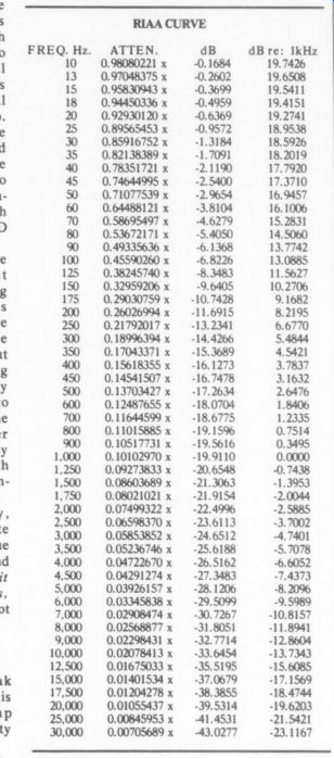
THE RIAA charts of Mr. Snyder and Mr. Jung disagree (TAA 3/ 78, pp. 51 and 56). Of course Jung's is correct. The table below verifies that and also should put all questions on the subject to rest.
The chart was prepared by programming a home computer to calculate the relative magnitude of the impedance of a theoretical RIAA network with exact 3180, 318, and 75 microsecond time constants. All figures printed are significant. The computer calculates to 12 digits and rounds to what is shown.
DAVID CARLSTROM
Huntington Woods, MI 48070
Ahem, those figures are not Mr. Snyder's.
They belong to the RIAA itself and are reproduced from its official published chart. -Ed.
-------------
RIAA CURVE
NOISE IN ICs
IN DESCRIBING his J W-33 phono circuit, (Issue 1, 1978) Walt Jung states that the two stage design improves noise performance, among other benefits. I can understand the other benefits, but I don't see how two op amps could be anything but noisier than a single op amp. It seems to me the equivalent input noise of the input amplifier will be multiplied by the gain of the circuit, regardless of the number of stages, and any following stages will only add to the noise (although their contribution may be nearly insignificant). Hence, by this line of reasoning, the two-stage design should not have better noise performance than a one stage circuit.
Would Mr. Jung mind explaining (in 25,000 words or less) what's wrong with my reasoning? Another quick question: are any hobbyist type dealers carrying the 5534 yet?
DON STRAYER Endicott, NY 13760
Walt Jung replies:
Although it may not make sense at first, two op amps can be less noisy than one, but not for a direct reason.
The reason is that to reduce noise to a minimum in a phono stage you need to reduce the gain setting and EQ resistors to a minimum (see my article, 'Noise Control in IC OP Amps for Audio,' TAA Issue 3, 1978, p.27). If this is done, the RIAA capacitances become large, increasing drive requirements, potential distortion, etc. In my opinion, the problems this approach would create are more serious than the expense of an extra op amp. The extra (first stage) op amp allows a very low feedback resistance, such as the 200 Ohms of the WI-I's JW-33 circuit. The noise performance of such a two stage design can be superior if the first-stage gain is 10dB or more and the second-stage noise not excessive.
This is just one reason for my use of the two-stage phono circuit. The other reasons are discussed in my answer to Stanley P. Lipshitz (Issue 3, 1978, p.48).
Re the 5534, try Old Colony, Box 243, Peterborough, NH 03458.
RUDE EDITOR
IT IS AN ORDINARY COURTESY, universally practiced I believe, for an editor and author to discuss and agree on modifications to a magazine article in advance of publication, in private.
For an editor to jump into and out of an article is a rare and extraordinary self indulgence; even more so when the interruption is for a mere pun or other witticism. For an editor to interrupt four or five times in a single article [see pp. 4-10, Issue 2, 1978] whatever may be the intended effect, displays a certain rudeness to the author and a certain rudeness to the reader.
TED UZZLE
Cambridge MA 02139
The rarity of editorial self indulgence evident by italicized commentary within an author's text is more apparent than real. The majority of editors have no qualms whatever about introducing their own words and ideas in place of, or in addition to, those of the author-without any acknowledgement of any sort. I eschew that style of indulgence for the lesser evil of the italicized aside. I like my brand of rudeness better. -Ed.
RABCO INFO NEEDED
I'D APPRECIATE IT if anyone familiar with the Rabco ST-4 would supply data on the following topics:
1. alleviation of the small wheels' binding;
2. arm alignment,
3. general maintenance procedures.
I will forward the information I receive to other interested readers if they write to me.
LEWIS OFFSINK
8800 Shore Front Pkwy.
Rockaway Beach NY 11693
RABCO HUM
I HAVE A RABCO ST4 with a Grado F3E cartridge. The cartridge is connected correctly, per the owner's manual. The turntable grounds through one of the cartridge grounds, and is operative. Yet when I touch the metal part of the tonearm, I get a clearly audible hum over the speakers (with, of course, the volume turned up--and I might add it's no answer just to say, 'turn the volume down when you must handle the tonearm').
No hum and no problem when I don't touch the arm. But when I take an Ohmmeter reading between the arm and the preamp case (the common ground on the preamp), I get an approximately 600 Ohm figure. Has anyone heard of a similar problem and does anyone have suggestions for a possible cure.
I'm stumped and help would be really appreciated.
I'd also like to point out to anyone interested in time-delay or so-called '"'phase" effects in speakers an article in the Journal of the Audio Engineering Society, Vol. 20, No. $ (May 1978), entitled 'A Shuffleboard Experiment of Time-Delay Effects In Loud speakers'', by Gary C. Gillum. Though "hard'' verification is promised in later issues, his preliminary results suggest these effects may not be so important as some have contended.
JAMES M. RICE
Charlottesviile, VA 22903
ANYONE FIXED FONS?
HAS ANY OWNER of a Fons CQ-30 turntable fixed a problem of its running slow when first turned on? Once it's up to speed, after about five minutes, it's very stable.
I'd like to hear from readers who own the Fons because it's a fantastic table; un fortunately the com pany that made it is out of business. Does anyone know of a source for precision-ground drive belts, since these are unavailable from the manufacturer?
ANDY WEIS Austin, TX 78746
PRESTON PRAISES BRIAN PRESTON''S excellent article in the 4/1978 issue left me watering at the mouth.
Not many of us can play around in our (amateur) field recordings with such exotic gear.
However...be of good cheer! The same techniques he described applied diligently to lesser mikes and decks will yield results almost head and shoulders over the 2nd or 3rd generation (with snaps, crackles and pops) stuff we get from the record stores. The co incident pair of 451-E's by AKG has been my mainstay for years with occasional accent mikes when needed. Sometimes there is a rare "unpleasant" hall which doesn't yield to this set-up, and I have found in such cases a spaced pair carefully placed will many times eliminate what I shall call, for want of a better description, ''room resonance." Some might call it a "boxy" sound.
It is encouraging to see material such as this in TAA'S pages. Those of us who aren't 100 percent occupied with building, designing and debugging like to know what the stuff is USED for! P.S. Listeners who are into tape recording and who haven't yet tried the dbx-120 series companders will find it a revelation to do so.
Imagine 110dB dynamic range and no hiss!! Even the Nagra and Studer won't do that- but I've done it with the Crown!
JAMES E. JOBSON
Austell, GA 30001
WITH THE KIND PERMISSION of Crown International we reprint below an excerpt from the manual for their splendid IC-150A preamplifier.
MURPHY'S LAW
Throughout the design, production, and sale of the IC-150, consideration has been given to the effects of one Edsel Murphy. Mr. Murphy (or Murphy's law) stated that, ''If anything can go wrong, it will." This being the broadest scope of Murphy's law, let's now offer a small sample of the application of the law with regard to the IC-150. (Note: Crown does not adhere to these below mentioned laws!) ___ which is the mathematical symbol for 'hardly ever.’
I.1. All warranty and guarantee clauses become void upon payment of invoice.
I.2. Dimensions will always be expressed in the least usable terms. Velocity, for example, will be expressed in furlongs per fortnight.
II.1. Identical units tested under identical conditions will not be identical in the field.
II.2. A dropped tool will land where it can do the most damage. (Also known as the law of selective gravitation.)
II.3. The probability of a dimension being omitted from a plan or drawing is directly proportional to its importance.
II.4. Interchangeable parts won't.
II.5 Probability of failure of a component, assembly, subsystem or system is inversely proportional to ease of repair or replacement.
II.6. If a circuit cannot fail, it will.
II.7. A fail-safe circuit will destroy others.
II.8. A transistor protected by a fast-acting fuse will protect the fuse by blowing first.
II.9. A failure will not appear until a unit has passed final inspection.
II.10. A purchased component or instrument will meet its specs long enough, and only long enough, to pass incoming inspection.
III.1. Manufacturer's spec sheets will be incorrect by a factor of 0.5to 2.0 depending on which multiplier gives the most optimistic value. For salesmen’s claims these factors will be 0.1 or 10.0.
III.2. In specifications, Murphy's supersedes Ohm's.
STEREO 70 MOD Law
I READ WITH INTEREST the Stereo 70 modification by H. L. Eisenson (Issue 4, 1976, p-13). As an old vacuum tube amplifier builder, I was amused by some of the ideas and suggestions. His basic change is to remove the overall feedback, and make the output stage one with local cathode feedback.
This has the disadvantage of increasing the drive required by about 25 percent, and eliminating the feedback for the first two stages. This appears to change the whole design concept as created by Dynaco (originally D. T. N. Williamson).
I would suggest the improvement, if any, propter hoc...at all.
achieved by the ''modification'' is due to an improved power supply, better resistors, and probably better balance. Filial pride is unquestionably a factor. Post hoc, ergo I offer a few suggestions. Remove the first and second filter sections, and the filter choke. Replace them all with a SOF capacitor-two 100: F 350 Volt units wired in series. Even bigger capacitors can be used.
I doubt that any changes in the bias supply are necessary. If one wants the exercise, one candoit. Ifit is done, there is no advantage to capacitors over 150 Volt rating.
The coupling capacitors are very important. It's probably a good idea to change them under any circumstances. They should be balanced as noted, and checked very carefully for leakage. First check them with an Ohmmeter, on the highest range. There should be no indication (after initial charge) Buy the best units you can get-Vitamin Q or other high quality units. After the units are wired in place, remove the output tubes and turn on the amplifier (after disconnecting the bias supply); there should then be no voltage (DC) on the grid resistors (input to amplifier grounded).
Alternatively, one can check the capacitors on a tester with a S00V setting to check for leakage.
An additional refinement that may further reduce hum is to increase the bypass capacitor on the screen of the input stage to 0.1 or larger, and if additional gain is needed bypass the 620 ohm cathode resistor with a 30 to 10x F capacitor at SO Volts.
I wouldn't try this latter with Eisenson's modification, since the unbypassed cathode resistor is the only feedback in the first stage.
ARTHUR D. FISHER
Beverly Hills, CA 90210
BOAK'S REGULATOR QUERIED
AN EXAMINATION OF the Boak regulator circuit for the Mark III (Issue 1, 1978, p.32) reveals that the transistor circuit is not a true voltage regulator of the type which could be | used in other amplifiers with similar Bt requirements. The transistor circuit compensates for voltage drops which happen to occur in the Mark III power transformer and choke filter as the amplifier's output increases. But with another power amplifier or another filter, the circuit is unlikely to work without revision.
I have other misgivings about this "regulator" circuit. I do not own a Mark III and have not tested the circuit, but its design would appear to cause some problems. I question, for example, whether it actually provides ''1 percent regulation," as the article implies, under all reasonable test and signal conditions. Also, due to the regulator's design, the modified Mark III may actually have higher distortion than the original on transients and at high frequencies; this should be tested. Additionally, the circuit cannot maintain a steady 500 volt B+ at full amplifier output if the line voltage drops by more than five percent; if the line voltage drops by more than seven percent, the regulator becomes inoperative.
The answers to these misgivings could have been partially provided if a distortion analysis had accompanied the article, to indicate the degree of change effected by this modification.
In spite of these criticisms, I appreciate such articles and look forward to more. I do prefer the 'sound' of good tube amplifiers.
JOHN L. HODGE
El Cerrito, CA 94530
MR. BOAK REPLIES:
MR. HODGE DOES NOT indicate the calculations on which his conclusions are based. The voltage regulator I designed for the Mark III is essentially an emitter follower, the same well-tried circuit which has formed the basis of the overwhelming majority of commercial series pass regulators on the market. The unique aspect of this circuit is the source of the reference voltage which the emitter follows. The use of the current source for this purpose is common practice in monolithic IC regulator design, but is not often used for discrete realizations.
The resulting circuit is a perfectly general supply which can supply up to several amperes at any voltage from less than 100 volts to more than 1,000 volts, with an adjustment of more than 100% around the design center value. Although the regulator can be optimized for particular applications, the circuit published in the 1/ 78 issue can be applied to any device requiring between 100 and 600 volts without a single component change.
The heatsink specified would be adequate for any device drawing less than about .S amperes; devices requiring more current can be accommodated with a larger heatsink. I think the applicability of the regulator is an important factor, and considerable design time has been spent to assure that this design could eaily be applied to preamps, bias supplies, and other loads requiring clean, stable power.
----- FIGURE1
The accepted meaning(1) of the term *'% regulation' is:
(1) (No-Load Voltage) - (Full Voltage) / (No-Load Voltage)
This is a static measure; the dynamic measure is output impedance. The No-Load Voltage of the regulated supply as described in the article was 495V, while the Full-Load Voltage was 491V measured into a static (resistive) load. This gives percent regulation of 495-491/ 495 or .808% The question of line-voltage regulation is addressed sparingly in the article, but was certainly not neglected in my own design process. The regulation range is set by the V of the pass element, in this case 62 volts determined by the Zener diode mD3. If we allow 50 volts across TR2 during normal no signal operation, we can accommodate a 10% low line. At full load this margin may decrease somewhat, depending on the "raw" supply. My unit left about 20 volts at full load, or about 4% low-line margin. If this seems an uncomfortable margin, it can be increased by using higher-voltage parts in the regulator.
Table 1 shows part values for regulators at various voltages, for line regulation of plus or minus 5, 10, and 30%. The last of these would provide a stable regulated voltage against a line variation from 84 volts to 156 volts. We would have to provide the margin of voltage either by lowering the output voltage (which in a sense defeats the purpose of the regulator) or by beefing up the power trans former secondary to provide the required S15 volts from the lowest (84V) line into a full load.
TABLE ONE
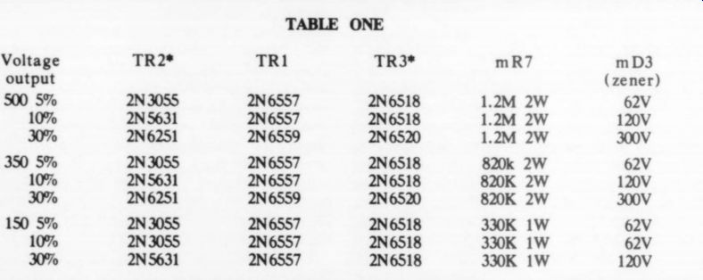
Part Numbers refer to the 1/ 78 article. *Darlingtons are replaced by two each of the indicated single transistors, connected in the Darlington configuration.
TABLE TWO
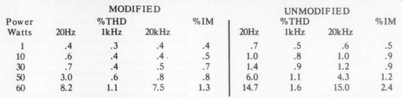
Measured distortion for modified and unmodified Dyna Mark III ---- The high distortion figures at higher power levels represent clipping distortion; the limiting discussed in the article produces these high values.
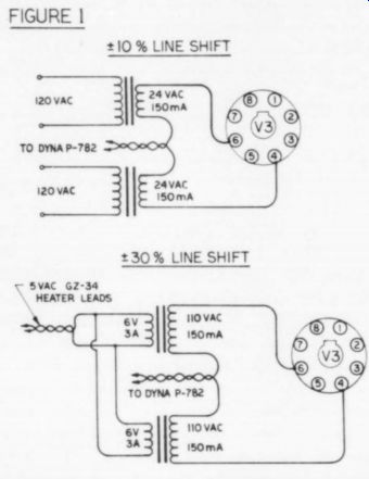
Several good methods are available to do this, the simplest of which is probably to connect a 24 volt transformer in series with the power transformer high-voltage leads.
See Fig. 1. Be sure the voltages add: if the new AC voltage is lower than the Dyna P782 alone, reverse the new transformer leads.
This should be done before testing the diodes, as the new rectified full-load voltage will be nearly 3SV higher than before. This would allow a 10% low -line. The 30% low -line circuit might be powered by connecting the secondaries of two 6V transformers to the GZ-34 heater leads. The primaries would then be wired in series with the supply leads. This would boost raw B+ by 150V, which requires some high grade diodes (1500 PIV) to avoid breakdown.
We must also increase the input capacitor voltage rating. Referring to Fig. 3 of the 1/78 article, mC1 and mC2 should be changed to 2:F, 250 volt types. mR1 and mR2 are changed to 2M2 values to properly divide the capacitor voltages.
The output voltage is adjusted to 500 volts (or any desired voltage) by connecting a voltmeter between the emitter of TR2 and ground. mVRI1 is then adjusted to set the output voltage. From a normal line, there will be about 70-80 volts across TR2 for the plus or minus 10% line-regulated version, and 150-180 volts for the 30% circuit. This margin allows us to provide full power from the lowest line without going out of regulation.
The choke has a DC resistance of less than 10 ohms. The resulting drop of a volt or so under load is negligible, and was not a design consideration. The choke was left in primarily to prevent breakdown of TR2 on a short circuit of the output.
The question of distortion can best be answered on the test bench. See Table 2. I did not include distortion analysis in the original article for two reasons. First, the modification did not involve the audio circuitry directly. Second, and more important, the distortion figures on tube equipment are not very impressive when compared to the best transistor designs, yet the ear often finds the tube sound more appealing. My Marantz 250 was clocked at less than .001% THD and IM at 125W; nonetheless, it does not sound 1,000 times better than the Dyna Mark III.
Rather than obscure the results with ’traditional’ measurements that are more valuable as design tools than as performance specifications, I relied on subjective appraisals. For those who prefer the hard specs, I de-modified one of my Mark III's and ran the test in Fig. 2.
On the matter of transient response, both the original regulator and the modified version benefit from improved energy storage at high frequencies. This can be seen from:
(2) i= Cdv/ dt
...when we let the differential be replaced by the finite interval ...
(3) i= C delta v/ delta t
We can allow a 30 volt drop using the settings described in the article, so Av is = 20V. At is the inverse of the operating frequency of interest. Since the full load current is 300m A, i= .3A. Cis the combined input capacitance, about 40x10°6F. We can rearrange (3) as (4)
delta t= C delta v/ i
Substituting, we find
t= 40x10 ^-6 x 30/0 .3= 4x10^-4
The reciprocal of this is the lowest frequency at which the capacitor alone independent of the transformer, can supply a complete cycle of sull-power output. In this case that frequency is 2500Hz at 20kHz we can provide eight complete cycles.
The regulator is thus guaranteed a good supply at high frequencies. The other factor which might affect transient response is the value of F_t, the unity gain frequency, of the pass element. For the 2N30SS F, is greater than 2MHz. The high closed-loop gain assures that the reference will not be affected by load frequency variations.
I hope this explanation will clear up any misgivings any potential user might have about the possibilities of the circuit.
REFERENCE
1. Birman, The Kepco Power Supply Hand book, Kepco, Inc. 1965.
DISCOS: PRO & CON
Our guest editorialist in issue 3, 1978 was Sharon Maurer who works in disco establish ments in the Boston [Mass) area. She asked for some quality in choices of material and comments on her views. -Ed.
FEET OR EAR MUSIC
SHARON MAURER’s editorial came as a surprise to me (there's really someone else out there as concerned) as I find myself in a very similar, but even more complex, situation.
As operators of a mobile disco (for over four years), partner in a small audio consultation / sales/ manufacturing firm, and also recently manager of a discotheque, we run into almost all of the problems of the disco craze from selection of music, to installation of equipment, to the "type" of sound actually reproduced.
Aside from the immediate problems of the DJ (motivation of the crowd, music selection and mixing, operation of equipment, etc.) there remain so many conflicting opinions as to how a disco sound system should "sound" that we are currently conducting an informal survey of club owners, DJs, and people who go to discos for live and recorded music.
Many of my audiophile friends who go to discotheques find the sound unbearable to listen to; but to dance to this kind of sound (punchy bass and sizzling highs) becomes a totally different story.
One experiment we have conducted indicates that the sound system must be flexible enough to be fairly accurate or "punchy," depending on the crowd (and the EQ, room, recordings, etc.). We have on several occasions compared one of our own disco systems (using good electronics and speakers of our own design that are flexible). . .with very favorable results.
I would be interested in hearing from other TAA readers on this subject.
FRED JANOSKY; Alpha Sound + Light
Hazleton PA 18201
MOUSTACHING MONA
MS MAURER RAISES some points that bear answering but before I speak, I probably should list my credentials.
An audio hobbyist of some 17 years, I began doing public address and recording work in high school, including tapes for local performers, and rock and roll groups. I build my own speaker systems and have never owned a commercially built one. I do sound for several theaters including musical shows and special effects. I design and build audio accessories, including control and switching boxes and patch panels. I have experience with large halls and loud sound reproduction as well as an FCC third class license.
I think Ms Maurer has a problem many audiophiles share. She has never come to grips with the aesthetics of recording.
A recording is not a live performance, it is the record producer's mental image of what the music (or whatever) should sound like when played through loudspeakers. The recording director must balance the recording so that the relevant details of the music are brought to the ears of the listener. He must do this because the visual and spatial cues that are present in the concert hall are not present in the listening room at home.
When we are in the concert hall we can see the soloist playing, for instance, so we can listen to him. The blank wall between our loudspeakers gives us no such information.
We do not share physical and emotional ambiance of the hall with the performers and the conductor. We are listening to a record.
The recording director is attempting to synthesize this experience in our listening room. He is not giving us a live performance.
If he is sophisticated and artistic, he will preserve the illusion of live music even though what comes out of the speakers may bear no resemblance whatsoever to what was heard on the recording floor.
The stereo system's purpose is not to recreate a live performance in our listening room, any more than the purpose of a movie projector is to bring celluloid images of actors to life. The purpose of the stereo system is to decode a recording in such a way that we hear in our listening room the recording director's image of the music as he thought it should sound.
This brings me to my point. I object to the notion that one can fecklessly diddle with equalization in such a way as to lay one's own notion of what constitutes ''good sound' over the recorded music as the record producer wanted it to be heard. It's a little like painting a mustache on the Mona Lisa, because you have the notion that all Italian women have hairy upper lips. You're sort of stuck with the way Leonardo saw the girl, regardless of what you may think of it, and his vision deserves respect.
I realize that high volume demands that the system be equalized in such a way that the sound will come forth properly, particularly since the program material may not have been designed to play at such high levels, but this should be more in the way of getting the system straight than altering the program.
There may be some artistic reason for that heavy bass line. The reproducing engineer may have to cut it back a little so that it will reproduce clearly and naturally given the characteristics of the human ear and the particular listening environment. But he should be thinking in terms of correcting the sound system rather than the program material.
What counts, of course, is results. If Ms Maurer has a good ear and good artistic sense, she probably gets good results. I find that I have a terrible problem with her attitude, though. If Beethoven put the oboe in the score, we should reproduce the oboe in the way that the conductor and the recording director wanted it to be heard, and not delete it from the record because we don't happen to like the sound of oboes.
I am currently using a small speaker of my own design in theatrical applications. It takes a good deal of power (about 30 watts) and two will adequately fill a small hall. It is also cheap. Mine cost about $30 apiece. Ms Maurer could park six or seven of them around a room and get enough level to give everybody a nosebleed. If she, or anybody else, is interested I will be glad to correspond.
JOSEPH A ZANNIERI
46 Gariea Dr.
Norwalk OH 44857
DOUBTS DISCO DEVOTION
I CERTAINLY AGREE that disco is ''of considerable cultural importance' and that the equipment and techniques involved can be fascinating. I cannot, however, condone any attempt to dignify the stuff with any great attention.
I have been in the club scene for some time now, both as musician and sound technician.
"Disco music' has to be one of those great contradictions such as '"'plastic glass' or
"religious war." In live clubs, you find people who love and care about music; in discos you simply do not. Can you imagine a disco musician starving for his art? Or a fan keenly following the career of some disco prodigy? Sure.
Okay, taste is taste. But some people are there for the music and some people aren't.
On whom shall we spend our dear, finite time?
HILARY PAPROCKI; Rochester NY 14607 USA
DUBIOUS, DAMAGING
IT IS MY UNDERSTANDING that disco sound is, if nothing else, loud. There exist abundant data which show that irreversible hearing injury is proportional to (SPL) x (duration exposure). [See TAA issue I, 1972, p- 36.] Widely circulated general audience magazines (e.g., Consumer Reports) take cognizance of this relationship. CU now includes noise ratings in evaluating certain products.
I am sure Ms Maurer has valid, perhaps interesting, technical problems in her disco ventures. That TAA's expertise should be addressed to these problems is another question. Technological developments applied to systems which injure human health are, in my opinion, dubious undertakings.
The current popularity of disco sound (or, indeed of massive home sound systems devoted to high volume rock) offers little justification. We are slow to learn the obvious: cigarette smoking ( = lung cancer) and alcohol abuse ( = cirrhosis) remain major health problems in which man destroys himself. Knowingly.
ROBERT DRUYAN, M.D.
Hinsdale IL 60521 USA
--------
Also see:
Audio Aids, by readers Squires, Hill, Caldwell, Thompson, Winn, Hardwick, Moritko, and White