by DAVID ROSS
THIS NOTE IS INTENDED to shed some analytical light on the results of H.L. Eisenson's experiments with the ''not-quite-passive-radiator.''! For those who missed the article, the NQPR is a speaker system using a complete speaker, with an electrical network attached to its terminals, as a passive radiator. Electroacoustic systems such as these can be represented by lumped-element equivalent circuits and analyzed by standard network theory.
The details of generating the equivalent circuits and the equations which govern their operation are tedious and are not offered here: for these I refer the reader to any of the excellent texts on acoustics? I intend, rather, to present some equivalent circuits as faits accomplis, and to use them to explain Eisenson's observations.
BACKGROUND
In order to understand the value of the NQPR, we must recognize that this system-like the passive radiator from which it is derived-is functionally a bass-reflex system, wherein the un driven cone serves as a vent sub stitute. Olson, who patented the idea in 1953, has given the reasons for using the cone rather than a simple port. Basically, he asserts, the cone offers a more uniform particle velocity across its surface, and lower viscous losses, than an equivalent port- presumably yielding a better-formed, higher-energy wavefront at those frequencies where the port dominates the system's output.
The parameters of the vent substitute are subject to the same tuning constraints as vents of the hole-in-the wall variety. As Thiele has shown, for any given driver a unique, small set of vent/enclosure combinations, corresponding to different filter alignments, will yield extended bass response with low ripple. In many cases, in fact, only one solution can be realized without either an auxiliary equalizer or a negative output impedance in the driver amplifier. (The Thiele paper should be considered required reading for anyone at tempting any type of vented speaker design; his design algorithm is easy to follow and leads quickly to an optimum choice of cabinet volume and vent tuning for a given driver.) The mechanism for tuning a hole in-the-wall is quite simple: either cut it open further, or block part of it off.
Tuning a cone, however, is obviously another matter. One had better be close on the first try, or be prepared to start over. The difficulty of tuning the vent substitute has generally restricted the successful use of this technique to some of the more sophisticated manufacturers, who can afford to custom-design and manufacture special radiator units.
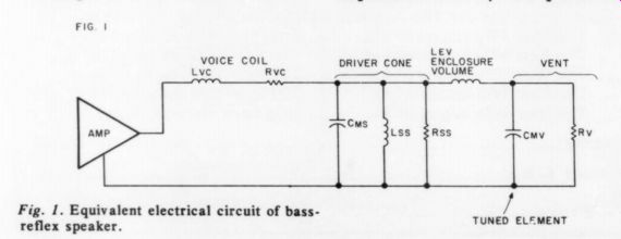
Fig. 1. Equivalent electrical circuit of bass reflex speaker.
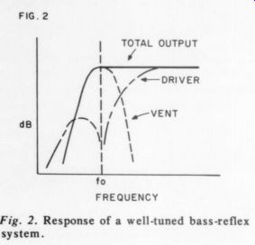
Fig. 2. Response of a well-tuned bass-reflex system.
Enter the not-quite-passive radiator. By attaching the undriven cone to a coil suspended in a magnetic field, i.e. using a complete speaker, we may use the motion of the cone to generate an electrical current in a network connected across the output terminals. The electrical impedance seen by this current will, in turn, affect the motion of the cone-just the inverse of the process by which the mechanical properties of the driver/enclosure affect the electrical impedance seen by the power amplifier. Thus, in principle, one can fine-tune the mechanical properties of the passive radiator by adjusting an electrical network attached to the terminals of the undriven speaker.
TUNING OBJECTIVES
In order to see what the system tuning is to accomplish, let us look at the basic bass-reflex system and its relationship to the passive radiator and NQPR.
Bass Reflex
Fig. 1 shows the equivalent electrical circuit which the bass-reflex presents to the driving amplifier. The circuit consists of the electrical impedance of the voice coil in series with a circuit representing the electrical impedance induced by the mechanical speaker/enclosure system.
The main point to take from Fig. 1 is that one varies Cmv (representing the mass of air in the vent) in tuning the bass-reflex enclosure. More specifically, one varies the resonant frequency
fo=1 / 2 pi radic [LEvCmv]
at which the driver is effectively ''short-circuited'' and power radiates only from the vent (Rv). Properly placing this peak in vent output optimizes the response-frequency characteristic, as shown in Fig. 2. A reduction in low-frequency distortion typically results from the reduced motion of the driver cone in the vicinity of fo, as Eisenson notes.
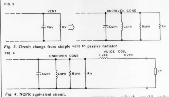
Fig. 3. Circuit change from simple vent to passive radiator.
Fig. 4. NQPR equivalent circuit.
Passive Radiator
When the simple vent or port is replaced by a speaker cone, Fig. 1's circuit is modified as in Fig. 3. The passive radiator has a self resonance at
fpr = 1/ 2 π / √ [Cmpr Lspr]
but only above this resonance (where Cmpr dominates the immitance) will the cone function as a vent substitute to extend bass response. For an un driven cone to be useful in this respect, its self-resonance must be below the lowest desired system resonance-hence Eisenson's success with large, mass-laden cones. Un fortunately, aside from adding mass (i.e., increasing Cmpr) one can do little to tune the passive radiator cone.
Not-Quite-Passive-Radiator
Fig. 4 shows the NQPR equivalent circuit. At low frequencies the voice coil impedance is fairly small, so the terminating impedance Zt effectively becomes a variable element in the passive radiator resonant circuit; one can use this to tune the self-resonance for the best system response.
Choosing Zt
Eisenson suggests a number of circuits for Zt. Indeed a limitless number are possible, but I believe the foregoing analysis shows that only a few will be of practical value. The most obvious is a simple capacitor, which will augment Cmpr and lower the self resonance, and could eliminate the need to use a massive cone-a significant economy. An inductor will raise the self resonance, in the rare case where that is desired. Adding resistance will lower the Q of the resonance, which could reduce ''boom''; but, in general, this method is less desirable than retuning the system resonance. A well-designed reactive system will not boom, and will be more efficient than a resistively-loaded one.* No doubt someone has tried using the derived current in the voice coil to drive a negative feedback loop around the power amplifier. My impression of commercial feedback systems is that their performance doesn't justify their additional cost and complexity, not to mention the inherent stability problems. To any amateur who tries it, good luck.
SUMMARY and CONCLUSIONS
I have shown above that the not-quite passive-radiator may be treated as a tunable vent-substitute system, and that tuning is probably best accomplished by a simple capacitor, or perhaps an inductor. This trick can be handy for the amateur who happens to have extra speakers lying around for use as passive radiators; but commercial designers would probably find it cheaper in the long run to design a cone with the right properties, and to dispense with the magnet/voice coil assembly necessary for the NQPR.
REFERENCES
1. Eisenson, H.L., "Experiments with the Not Quite Passive Radiator," The Audio Amateur, Issue 1, 1977, p. 18.
2. Beranek, L.L., Acoustics, New York, N.Y., 1959.
3. Olson, H.F., Acoustical Engineering, D. Van Nostrand Co., Inc., Princeton, N.J., 1957.
4. Thiele, A.N., "Loudspeakers in Vented Boxes,' Journal of the Audio Engineering Society , Vol. 19: Part I, May 1971, pp. 382-391; Part II, June 1971, pp. 471-483. McGraw-Hill,
--------
Also see:
Audio Aids, by readers Squires, Hill, Caldwell, Thompson, Winn, Hardwick, Moritko, and White