Manufacturer's Specifications
System Type: Three-way, aligned-driver, floor-standing, dynamic di-pole system.
Drivers: 10-in. carbon-polypropylene cone woofer, 5-in. open-back cone midrange, 1-in. polymer-dome front tweeter, and 3/4-in. dome piezo rear tweeter.
Frequency Range: 44 Hz to 24 kHz.
Sensitivity: 88 dB at 1 meter with 2.83 V rms applied.
Crossover Frequencies and Filter Slopes: 450 Hz (12-dB/octave low pass, 6-dB/octave high pass) and 3.15 kHz (6 dB/octave).
Impedance: Nominal, 6 ohms; minimum, 4 ohms.
Recommended Amplifier Power: 20 to 300 watts per channel.
Dimensions: 27 3/4 in. H x 20 1/4 in. W x 12 in. D (70.5 cm x 51.4 cm x 30.5 cm) without stand; stand, 8 in. H x 21 in. W x 12 in. D (20.3 cm x 53.3 cm x 30.5 cm).
Weight: 40 lbs. (18.2 kg) each with out stand.
Finish: Natural granite; black, white, or dark granite; high-gloss black or white granite.
Prices: $999 to $1,145 per pair, depending on finish; stands, $159 to $199 per pair, depending on finish; Electronic Foundation Control stereo equalizer, $319.
Company Address: 2363 Teller Rd., #115, Newbury Park, Cal. 91320, USA.
Bright Star Audio, a relative newcomer to the high-end loudspeaker market, was founded in 1989 by Barry Kohan, who, after 14 years managing a chain of high-end audio salons in the Los Angeles area, decided to go into business for himself. Kohan's previous background as a professional musician and part-time loudspeaker designer prepared him well for this endeavor. His early love of the involving sound produced by dipole-based speakers such as the old ESS AMT 1, which utilized the Heil Air Motion Transformer, challenged him to design a reasonable size, moderate-price, direct-radiator dipole system that would exhibit some of the excellent qualities he remembered.
Kohan started out by selecting a good midrange driver and then working out a unique hidden behind-the-panel mounting scheme that provides a rounded sound-radiating aperture to minimize interference and diffraction. The desired dipole nature of the system dictated that the back of the midrange be open to radiate freely to the rear. To provide dipole radiation at the highest frequencies, and knowing that no high-quality bidirectional direct-radiator tweeters were available, he added a rear-mounted tweeter, wired with reversed polarity. To keep the system of reason able size, true dipole radiation was sacrificed at the low end, where a quasi-closed-box system with a highly damped rear port was used. To acoustically align the drivers for coherent time response, the baffle was tilted back.
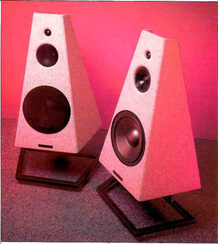
This process eventually lead to the unusual design of the Altair system. On first sight it looks like none that you have seen before. It is a tall, truncated pyramid coated with a granite-like material. The three circular shapes on the front panel locate the system's drivers, but closer examination reveals no obvious means of driver attachment, only gentle rounded surfaces. The lower two drivers, the woofer and midrange, are protected by rigid metal-screen grilles. The tapering enclosure minimizes the baffle area around each driver, improving dispersion.
A large section of the enclosure is open at the rear, exposing the backs of the tweeter and midrange. However, the sides continue upward, forming slanted wings that direct the signal radiated from the midrange straight back. An additional small dome tweeter is mounted on the sloping top of the woofer enclosure, aimed upward and slightly back.
All exposed surfaces, including the bottom and inside top rear of the cabinet, are covered with a quite good-looking granite-like material that leaves no evidence of the underlying wooden construction. In addition, all corners and edges of the structure are rounded to minimize diffraction. The shape of the enclosure means that none of the walls are parallel to each other, which reduces the effect of internal standing waves and strengthens the assembly. The exposed wiring of the tweeter and midrange is dressed and treated very tastefully, with shrink-wrap tubing over the soldered driver terminals and tie-downs.
The bottom rear of the cabinet had separate input terminal cups for the woofer and midrange/tweeter connections, with short pairs of heavy Tara Labs cable provided to link the cups for single wiring. Units now in production have all the connections in a single cup, with heavy go d-plated straps instead of cable links. A fiberglass-filled Scan-Speak aperiodic loading chamber (a type of vent active only when cabinet pressure exceeds a preset level), 4 inches in diameter, is mounted above the terminal cups.
Bright Star offers a separate line-level equalizer, the Electronic Foundation Control (EFC), which is said to extend the response of the Altair down to 32 Hz and to smooth the low-frequency response. The speaker system is designed to be used with an optional metal stand, which raises it to the proper height for a seated listener.
The enclosure is constructed from medium-density fiber board, 3/4 inch thick, and covered on all sides with multiple applications of Bright Star's granite-like spray coating. Multiple coats of a flexible rubber-like damping material that Bright Star calls "flexible borosilicate" have been applied to the open areas at the rear of the enclosure (under the granite-like coating), and to the inside of the woofer cabinet, to damp vibrations and control surface resonances: No internal bracing was evident (or needed) in the low-frequency enclosure, which is completely stuffed with a white polyester batting material.
The crossover of the Altair is wired point-to-point on a piece of 3/8-inch-thick particleboard mounted to the bottom of the enclosure. It contains 16 parts (two inductors, nine capacitors, and five resistors), though paralleling reduces the effective capacitor count to four. Both inductors are air-core types and are well separated. All capacitors are by passed with small-value, 600-V polystyrene capacitors. All signal-path capacitors are high-quality, high-voltage Mylar, polypropylene, or metallized polypropylene units. The 205 uF capacitor in parallel with the woofer is actually composed of three parts: A large electrolytic, with smaller value Mylar and polystyrene units in parallel. All internal wiring consists of paired Tara Labs Space and Time 18-gauge wires, paralleled to form roughly 16-gauge cable. All connections to and inside the Altair's crossover, and to the drivers, are soldered (using silver-based solder, according to Bright Star).
The design of the crossover consists of all first-order, 6 dB/octave networks for the midrange and tweeters plus a second-order, 12-dB/octave low-pass filter for the woofer. The midrange is connected via a second-order, series-connected LC bandpass filter, which functions as a 6-dB/ octave cascaded high-pass/low-pass combination. Bright Star states that they hand-match the crossover components between right and left speakers to within 1%. The piezo rear tweeter is driven through a series RC network that serves both to set level and provide protective high-frequency current limitation. The connections to the woofer part of the crossover and the midrange/tweeter portion are brought out separately to the rear of the cabinet to allow bi-wiring.
Measurements
Figure 1 shows 1-meter anechoic frequency responses of the Bright Star Audio Altair. In addition to the usual on-axis curve, the figure shows curves taken directly behind the system and 1 meter overhead, which is on the axis of the upward-facing tweeter. The front and rear measurements were taken at a distance of 2 meters, 36 inches from the bottom of the system (including stand), with 2.83 V rms applied and then referenced back to 1 meter. All curves except the overhead one were smoothed with a tenth-octave filter.
The on-axis curve is shown with and without the equalization provided by the Electronic Foundation Control equalizer, whose frequency response is shown in Fig. 2. With equalization, the on-axis curve fits within a tight, ±2 dB tolerance from 60 Hz to 20 kHz. The main effects of the equalizer are to pull down a woofer response peak in the range from 80 to 300 Hz and to extend the response below 50 Hz. The effect on frequency response of the Altair's metal grilles, which cover only the woofer and midrange, was minima0, less than ±0.2 dB over the whole range. All the following measurements, except for distortion, were made with the grilles in place. The right/left matching of the systems was quite good, about ±0.8 dB.
The rear on-axis output between 400 Hz and 1.6 kHz is actually 3 to 6 dB greater than the front output. The increased output in the rear is presumably due to the directivity of the midrange's rear radiation, channeled by the enclosure's side wings. The polarity of the rear output is reversed in this range, because thus signal comes from the back of the midrange cone.
Because the rear tweeter is essentially aimed upward, it contributes little output directly to the rear. The curve la belled "Above" in Fig. 1, measured directly on axis and 1 meter away from this tweeter, shows that the rear tweeter's output is about 6 to 10 dB below the level of the front tweeter. Its response is quite ragged due to numerous close reflections from the rear structure of the system.
The Electronic Foundation Control equalizer Bright Star supplied me was just a preproduction prototype, so I tested only its frequency response, impedance, and overload characteristics. Figure 2 shows a flat unity-gain response except for a relatively narrow, 11-dB peak at 23 Hz and a broader, 5.6-dB dip at 155 Hz. Below 3 Hz (not shown), the equalizer's response rolled off at 6 dB/octave. The EFC's audible frequency response is roughly reciprocal to the speaker's low-frequency response. I say roughly because, although the 155-Hz dip is a good match to the Altair's hump in this region, the 23-Hz peak is somewhat mis matched to the speaker's response and actually overcompensates, resulting in a narrow peak in the equalized response at 23 Hz (see Fig. 1).
The schematic of the equalizer disclosed the use of high speed AD712JN op-amps and all 1% tolerance resistors and 2% tolerance capacitors in the signal path. The EQ's input impedance measured about 330 kilohms, and the output impedance was about 100 ohms.
The equalizer's overload (clipping) point occurred at an output level of 10.5 V rms, about ± 15 V peak, though the unit did not overload gracefully. When the lower-15 V supply rail was reached, during the negative part of the sine wave, the output voltage would switch very rapidly to the + 15 V supply rail, then return rapidly to the negative rail when the negative portion of the wave came out of overload.
This essentially created a sharp-edged square wave at twice the input frequency for only slight sine-wave over loads. Fortunately, normal program material never attains levels that would trigger this overload. Only a situation where the equalizer was inserted between a preamp and power amplifier, and the power amplifier gain was turned down quite far (thus forcing the preamp and equalizer to operate at high levels for reasonable playback levels), might this occur.
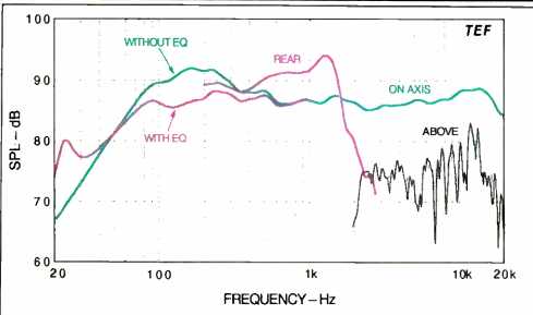
Fig. 1--One-meter, on-axis frequency response, with and without equalizer.
Also shown are 1-meter responses taken at the rear and above the system;
see text.
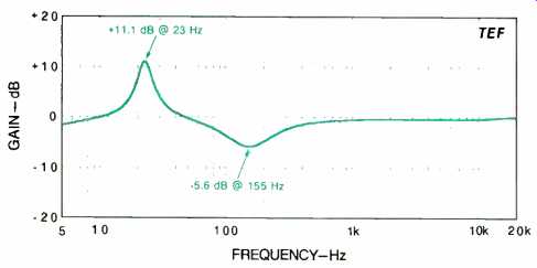
Fig. 2--Frequency response of the EFC equalizer.
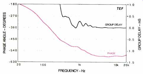
Fig. 3--On-axis phase response and group delay.
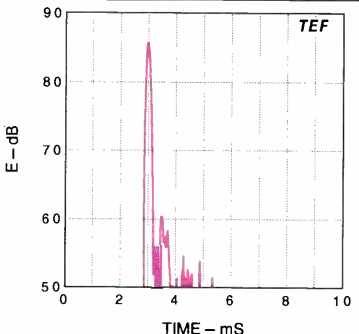
Fig. 4--Energy/time curve.
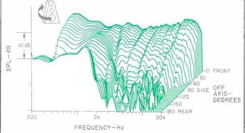
Fig. 5--Horizontal off-axis frequency responses.
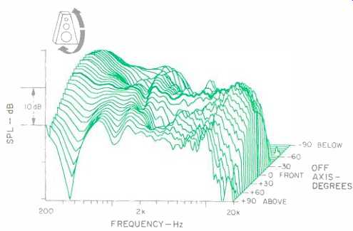
Fig. 6--Vertical off-axis responses.
Figure 3 shows the phase and group delay responses of the speaker, referenced to the tweeter arrival time. The phase curve is nearly flat, only rotating about 67° between 1 and 20 kHz. The group delay is also quite flat from 600 Hz to 20 kHz, a result of the careful alignment and positioning of the system's drivers. The fluctuations in group delay between 600 Hz and 2 kHz correspond mostly to minimum-phase deviations in the Altair's frequency response.
Figure 4 displays the system's excellent energy/time curve (ETC) for a test signal swept from 1 to 10 kHz. The Altair's alignment results in a very tight main arrival at 3 mS with only some minor late arrivals, 25 dB down.
The horizontal off-axis responses of the Altair are shown in Fig. 5. On-axis response is shown by the bold curve at the rear. The horizontal coverage is very good, as the off-axis curves uniformly carry over the irregularities of the on-axis response. High-frequency coverage is maintained to be yond 15 kHz for angles out to about ± 40°. The 180° rear curve (seen in the front of the display) shows that the system's output actually exceeds the on-axis output by several dB in the range from 400 Hz to 1.6 kHz; as noted, this is due to the rear radiation of the speaker's midrange. The high rear curve obscures the off-axis dip in the mid range's response toward the sides, caused by the bidirectional midrange radiation.
The vertical off-axis curves are shown in Fig. 6, with the on-axis response curve shown in bold. Fortunately, within the main ± 15° listening window, the above-axis curves are the flattest. Only below axis do the expected off-axis dips occur in the response (not clearly shown in the graph because of the above-axis viewpoint). These up/down response asymmetries are the primary indication of lobing, indicating that there is a significant difference in acoustic phase between the midrange and tweeter outputs through the crossover region.
The mean axial ( + 15° to - 15°) horizontal response curve in Fig. 7 is quite smooth and essentially the same as the on-axis response. The 30° to 45° off-axis response is also close to the axial curve but is somewhat rougher and lower in level above 1 kHz, coupled with rapid roll-off above 13 kHz. The 60° to 75° off-axis response is two-tiered, shelved down above 1.4 kHz by about 8 dB. Rapid roll-off above 11 kHz is also noted. The individual horizontal curves, averaged to yield the mean curves, all grouped quite close together.
The mean vertical axial curve (Fig. 8) reflects the increased directivity of the system in the vertical plane. Response is generally uneven, with a dip at 3.6 kHz. Examination of the individual curves averaged to make the-± 15° mean axial curve (not shown) revealed that the up curves (+5° to + 15°) were significantly flatter than the down curves (-5° to -15°). The 3.6-kHz dip in the mean axial curve is a result of interference at crossover in the down ward direction. Fortunately, the response in the upward direction, which is heard by standing listeners, exhibits the smoothest responses. The 30° to 45° and 60° to 75° mean curves are more uneven than the mean axial curve and have greater high-frequency roll-off above 11 kHz. As be fore, considering the individual curves that make up the averaged curves, the up curves are significantly smoother than the down ones.
Figure 9 shows the Altair's impedance. Three low points are evident, with the lowest, 3.6 ohms, at 150 Hz. A peak of 24.4 ohms is reached at 4.3 kHz. This corresponds to a fairly high max/min variation of 6.8 to 1, so the systems will be quite sensitive to series cable resistance, which should be limited to a maximum of about 50 milliohms to keep from causing response peaks and dips greater than 0.1 dB. For a standard run of about 10 feet, 14-gauge or larger wire should be used.
The complex impedance is shown in Fig. 10. The phase angle of the impedance (not shown) reached a maximum of +41° (inductive) at 300 Hz and a minimum of -39° (capacitive) at 71 Hz. The system will be a relatively easy load for most amplifiers.
A high-level low-frequency sine-wave sweep revealed a very solid enclosure with no significant cabinet resonances.
The grille over the woofer did resonate slightly at about 180 or 190 Hz. The woofer did not exhibit any dynamic offset effects, a rare characteristic. Some whistling and air-rush noises from the damped rear port were evident at high bass input levels. The woofer enclosure was quite well sealed; it took about 1 S for the woofer to return to its rest position when manually depressed. This also shows that the flow resistance of the rear port is very high, so the port output should not contribute much to the total system output.
Near-field curves run on the Altair's woofer and rear port (not shown) indicated that the rear port's output was at least 10 dB lower than the woofer's through most of the low-frequency range. Essentially, the low-frequency portion of the Bright Star system operates as a closed box. In this situation, however, the high port losses do somewhat reduce the hump in the low-frequency response caused by the woofer's somewhat small enclosure. Displacement measurements of the woofer cone with high input levels, with the port open and closed, did show that the port reduced cone displacement somewhat in the range from 30 to 60 Hz when the port was open.
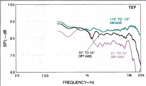
Fig. 7-Mean horizontal responses from Fig. 5 data.
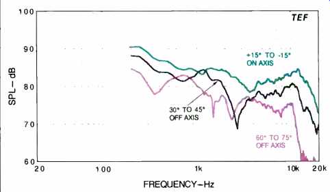
Fig. 8-Mean vertical responses from Fig. 6 data.
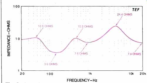
Fig. 9-Impedance.
Happily, the Altair could handle voltages in excess of 30 V rms (150 watts into 6 ohms), below 30 Hz, without generating any unacceptable noises! This is higher than any system I have measured. The woofer's linear excursion capability was a healthy 0.5 inch, peak to peak, with additional capacity to 0.75 inch before hard limits were reached. The system's high low-frequency power handling is partly due to the woofer's excursion capability and to the added stiffness provided by the somewhat small enclosure.
Figure 11 shows the 3-meter room curve of the Altair with both raw and sixth-octave smoothed responses. The system was in the right-hand stereo position, aimed at the listening location, and the test microphone was placed at ear height (36 inches), at the listener's position on the sofa. The system was driven with a swept sine-wave signal of 2.83 V rms (corresponding to 1.33 watts into the rated 6-ohm load). The direct sound plus 13 mS of the room's reverberation are included. Between 2 and 18 kHz, the smoothed curve is quite flat, with a slight high-frequency emphasis, and fits a tight envelope of ±2.0 dB. Including the room dips below 1 kHz, the complete curve fits within a ±6.3 dB window from 100 Hz to 20 kHz.
Figures 12 and 13 show single-frequency harmonic distortion versus power for the musical notes E1 (41.2 Hz) and A2 (110 Hz). Distortion for our usual 440-Hz tone is not shown because the harmonics were below the detection floor of my test gear. The power levels were computed using the rated impedance of 6 ohms.
At full power, the second and third harmonics of E1 (41.2 Hz) reach only 2.8%, quite low for this kind of speaker system. Higher order harmonics are only significant above 10 watts. At 100 watts, the system generates about 98 dB SPL at 1 meter at 41.2 Hz.
The second and third harmonics of A2 (110 Hz) reach only about 1% at full power. The higher order harmonics are not significant. At 110 Hz, the system generates a loud 110 dB SPL at 1 meter, for 100 watts input.
Figure 14 shows the IM created by tones of 440 Hz (A4) and 41.2 Hz (E1) of equal input level. At 100 watts, the IM distortion reaches only 4.5%, a relatively low value due to the three-way system configuration. Overall, the Altair exhibited respectably low values of harmonic and IM distortion.
The short-term peak-power input and output capabilities of the system, as a function of frequency, measured using a 6.5-cycle tone burst with third-octave bandwidth, are shown in Fig. 15. The peak input power (calculated by assuming that the measured peak voltage was applied across the rated 6-ohm impedance) rises smoothly with frequency, reaching about 5,100 watts above 1.25 kHz (175 peak volts across the rated 6-ohm load). Between 100 and 250 Hz, the Altair actually taxed the output of my test amplifier because of its low impedance through this region. At 200 Hz and below, the speaker's power handling was excellent.
The upper curve in Fig. 15 shows the maximum sound pressure levels the system can generate at 1 meter on axis for the input levels shown in the lower curve. Also shown is the "room gain" of a typical listening room at low frequencies, which adds about 3 dB to the response at 80 Hz and 9 dB at 20 Hz. The peak acoustic output rises rapidly with frequency up to 160 Hz and then levels out at about 124 dB SPL. With room gain, the system exceeds 110 dB SPL above 40 Hz and 120 dB SPL above 90 Hz.
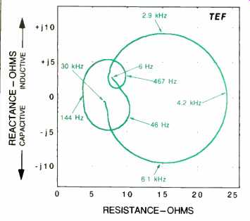
Fig. 10-Complex impedance.
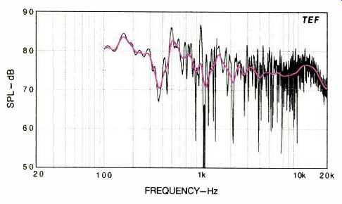
Fig. 11-Three-meter room response.
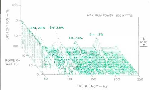
Fig. 12-Harmonic distortion of the musical tone E1 (41.2 Hz).
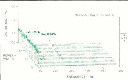
Fig. 13-Harmonic distortion of the musical tone A2 (110 Hz).
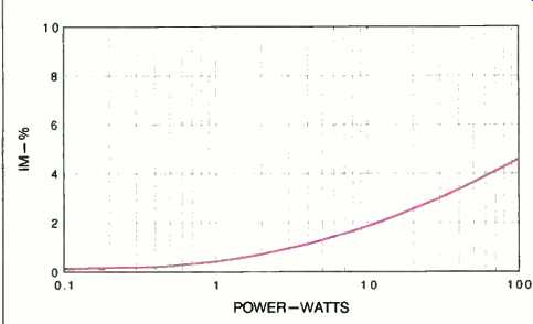
Fig. 14-IM distortion of 440 Hz (A4) and 41.2 Hz (E1) mixed in one-to-one
proportion.
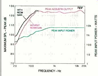
Fig. 15 Maximum input power and peak sound output.
Use and Listening Tests
Visually, the Altairs are very striking, quite modern and contemporary. The granite-like coating on the speakers fits quite well their modernistic high-tech look. Their pyramidal smooth-cornered contours are quite distinctive and create a very memorable appearance.
I was quite impressed with the printed documentation that came with the Altair. The eight-page owner's manual is quite complete and was supplied with several information sheets covering such topics as bi-wiring, power handling, and protection. The manual even starts out with the recommendation "that you always wash and dry your hands before handling the speakers," good advice for any system& The last two pages contain a list of 60 recommended audiophile quality recordings for use in auditioning the Altairs. In addition, a four-page manual was supplied with the Electronic Foundation Control equalizer.
The Altairs' optional stands are substantial, sand-filled, metal units with attached spikes. When the speakers are mounted on them, the tweeters are slightly above the ears of a listener seated 3 meters away. The 15° tilt of the systems' front panels means that the listener's ears are about 14° below the tweeter's axis.
Connections to the Altair are through multi-way binding posts on the bottom rear of the cabinet. The separate input terminals allow for bi-wiring or biamping. As noted, conventional single connection is accommodated by a set of short jumper links.
Fairly detailed placement instructions were included in the owner's manual. Bright Star recommends a location out from the wall and well away from surrounding objects to minimize early reflections. They emphasize that the speaker's dipole dispersion characteristics may require some experimentation to find the best cabinet position. The systems are supplied with absorptive pads, which Bright Star calls "rear wave controllers," for attenuating the midrange drivers' rear output. These pads allow you to fine-tune the proportion between the midrange's front and rear output levels. Bright Star does not recommend using the Altairs in so-called live-end/dead-end listening setups, where the region behind the speakers is highly absorptive. They recommend a reflective-diffusive environment behind the systems to properly handle the rear radiation.
I listened to the Altairs driven by Jeff Rowland amps and preamp and Onkyo and Rotel CD players with Straight Wire cables and interconnects. The systems were placed 10 feet from my sofa and separated by 8 feet-my usual source positions, and in agreement with Bright Star's recommendations. I found that the sound was best with the systems toed in toward my listening position but with their axes crossing a bit behind me. Most listening was done before the measurements, using both bi-wire and single-wire connections and with all grilles on.
On first listening, the Altairs presented a very spacious sound coupled with precise imaging and a revealing sense of depth. There were some problems in the upper bass, however, where the systems exhibited some excess fullness and a tendency towards tubbiness on male voice. The upper bass emphasis was also quite evident on pink noise, as the systems took on a moderate one-note tonal quality in this range. Subsequent use of the Electronic Foundation Control equalizer completely eliminated this emphasis. With the equalizer, the speakers' tonal balance was quite close to that of my reference B & W 801s. The Altairs' and B & Ws' sensitivity was also very close.
The EFC unit provided additional weight in the very low-frequency region, where the unaided system was somewhat deficient. The high boost of the EFC at low frequencies ( + 11 dB at 23 Hz) did not seem to restrict the speaker's power handling with most of the CDs I played. Only CDs that had high energy content from 20 to 25 Hz (such as the 20- and 25-Hz third-octave pink-noise bands on the Bruel & Kjaer CD-4090 Pro Audio test CD) presented headroom problems at high playback levels. The low-frequency power handling of the Altairs was superb on all the material I played. Even my favorite low-frequency test CD, the very demanding organ version of Mussorgksy's Pictures at an Exhibition (Dorian DOR-90117), was handled very well, generating clean and very respectable bass levels. The only noticeable problems occurred at high levels below 50 Hz, on the band-limited noise tracks on the B & K test disc, where the Altair's rear vent generated significant chuffing noises. Fortunately, these air-rush noises were attenuated significantly in front of the systems because of the vent's rear mounting.
I investigated the rear radiation characteristics of the loudspeaker by using the supplied rear-wave controller pads. With the midrange's rear output attenuated, there was a subtle but noticeable decrease in the spaciousness of the system's sound. I preferred the sound with the pads removed and left them off for most of the listening tests. At least in my listening room, I could tell no difference with the rear tweeters operating or covered up. Unless I stood directly over the speaker, with my head on the rear tweeter's axis, I couldn't tell the difference.
The Altairs' rear output was most evident when I walked from the front to the rear of the speakers along the center line between them. The sound of a conventional front-radiating system just simply collapses as you walk to the rear, but the sound of the Altairs held up very well in this test. When I listened at the rear, the tonal characteristic of the rear sound radiation was somewhat restricted and sounded quite "mid-rangy" (not unexpected, as it's mostly the midrange that radiates to the rear).
The Altairs exhibited only moderate changes in upper midrange response on the stand-up/sit-down pink-noise test. Unlike other phase-aligned systems, no "phasiness" was evident. Laterally, the Altairs' coverage was even and excellent.
The Bright Star systems are well suited for loud rock music, as authenticated on John Fogerty's Centerfield CD (Warner Bros. 25203-2); the percussion and vocals were reproduced very cleanly at high levels. John Bayless' piano playing on Bach on Abbey Road (Pro Arte CDD 346, Beatle melodies improvised in the style of J. S. Bach--a super performance and recording!) demonstrated the Altairs' smoothness, clean output, and dynamic range. The spacious nature of the Altairs' soundstage and accuracy of imaging were manifested by the choral movement, and especially the baritone solos, of Beethoven's Symphony No. 9, "Choral," with Otmar Suitner conducting the Berlin State Orchestra (Denon C37-7021).
Everything considered, the Altairs represent quite good value for the money. Even with optional stands and equalizer, the price is just slightly less than $1,500. These systems offer an excellent combination of super-modern good looks, impressive performance, low distortion and high power handling, and premium audiophile traits.
-D. B. Keele, Jr.
(adapted from Audio magazine, Jul. 1992)
Also see:
Boston Acoustics T1030 Speaker (Equip. Profile, Jan. 1991)
Link | --Boston Acoustics A40 Speaker (July 1983)
Cambridge Physics Model 310 Loudspeaker (Nov. 1982)
= = = =