Manufacturer's Specifications:
Frequency Range: 30 to 40,000 Hz.
Nominal Impedance: 8 ohms.
Dividing Frequencies: 45 Hz, acoustically coupled; 3,000 Hz, electrical cut-off slope 18 dB per octave.
Acoustic Contour Control: Three position ±2 dB, centered on 1,500 Hz.
Sensitivity: 12.5 watts into nominal 8 ohms produces 96 dB at one meter and 400 Hz in anechoic conditions.
Continuous Power Rating: 20 volts (50 watts) from 100 Hz to 2,500 Hz, reducing to 8 volts (8 watts) above 3,000 Hz.
Dimensions: 63 cm (24.8 in.) x 33 cm (13 in.) x 26 cm (10.2 in.).
Weight: 15.8 kg (35 lbs.).
Price: $425.00 each.
It is probably fair to say that most loudspeaker manufacturers now have access to computers or at least know what a computer can do. It is also fair to say that most loudspeaker manufacturers now know something about phase response and have at least a passing acquaintance with the phrase "time domain." But there had to be someone who was first; there had to be a manufacturer who, without prior advertising hoopla or pressure from their competition, borrowed an expensive computer to analyze the time domain and phase performance of their product, then laid out good money to buy a computer to assist in further design improvements on that product. KEF Electronics Ltd. in Kent, England was that company. However, KEF never blew horns or beat drums over what they did, so most persons not on the inside of this business are not aware of the mild revolution KEF started.
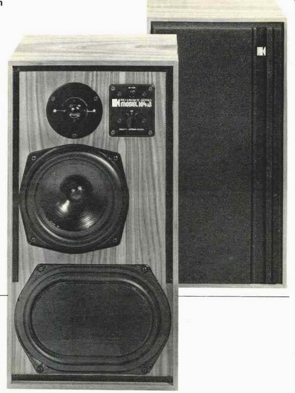
One of the first of KEF's commercial loudspeaker systems to benefit from computer analysis was their Model 104, which was introduced in 1973. KEF now has a number of computer-assisted-design loudspeaker systems in their inventory, but they recently upgraded the 104 with a new crossover design (using digital analysis techniques, of course). The system utilizes a new crossover circuit which KEF calls an acoustic Butterworth (aB) filter network, and the system is accordingly identified as the Model 104 aB.
The 104 aB uses two active drivers and a passive radiator. A 330-mm by 229-mm (13x9 in.) passive radiator is acoustically coupled with a 203-mm (8-in.) driver at frequencies below 45 Hz. The 203-mm driver crosses over at 3 kHz to a tweeter which carries the top end up to beyond 20 kHz.
The crossover network is unusual in two respects: (1) it is a third-order network with an asymptotic 18-dB-per-octave attenuation rate, and (2) it incorporates the driver-reflected impedances in its design. It does not, in other words, draw values from some handbook under the presumption that the loudspeaker which is to be connected to the network is a pure resistor.
The system is relatively small, measuring 630 x 330 x 260 mm (24.8 x 13 x 10.2 in.) and can be shelf mounted. But at a weight of 15.8 kg (35 lbs.), this system should have a sturdy shelf. To avoid overemphasis of the lower frequencies, KEF advises raising the cabinet by at least 200 mm (7.9 in.) above the floor.
Electrical connection to the system is made either by a two-pin DIN connector, using the cable supplied with each speaker, or via 4-mm sockets. Since most American power amplifiers will not accept the connector which is attached to the cable, it is necessary to use the 4-mm sockets. Unfortunately it is not possible to make good electrical contact without the aid of plugs, known commonly as "banana plugs." And since the spacing between these sockets is 35 mm, rather than the more conventional 20-mm spacing of American plugs, it will require the purchase and connection of additional connectors. Terminal polarity is indicated by small positive and negative symbols molded in the plastic receptacle holding the sockets, and the choice of basic black on-black renders the sockets extremely difficult to identify.
This appears quite out of keeping with the rest of the KEF design philosophy, particularly since the same receptacle holds a high-contrast label which tells the user that he has a KEF 104aB, the impedance, and the serial number, and I feel that the installer, perhaps crawling around on hands and knees with a flashlight in his teeth, would much rather see the polarity identification in high contrast, particularly it he's concerned with true acoustic polarity.
The foam grille is readily removed (and replaced) to reveal a three-position acoustic equalizer switch and the protective fuse for the high-frequency driver. The manufacturer thoughtfully provides spare fuses, which are a variety some what smaller in physical size than conventional fuses used in domestic loudspeakers.
KEF supplies a very thorough user's manual with each loudspeaker. Other than the possible difficulty with electrical connection to which I referred, even a totally nontechnical user should be able to follow the instructions to get proper performance from this loudspeaker system.
Technical Measurements
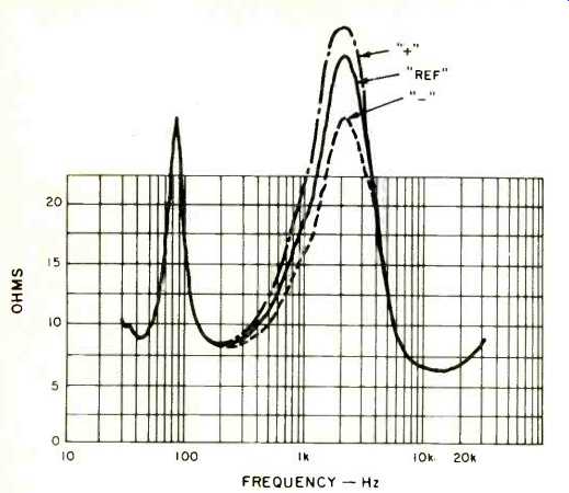
Fig. 1-Magnitude of impedance for each of the three equalizer settings.
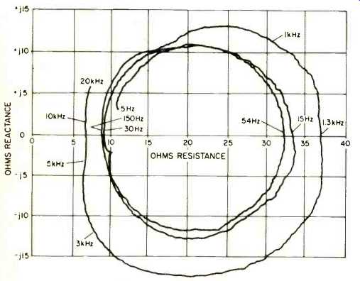
Fig. 2-Complex impedance plot for reference equalizer setting.
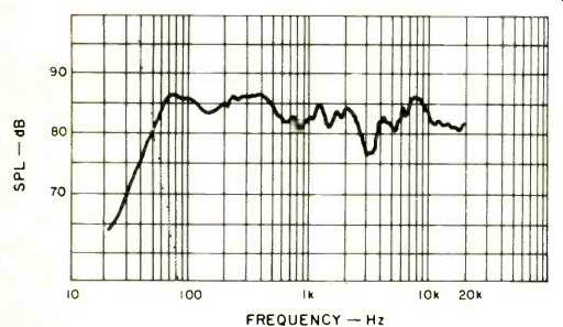
Fig. 3-One-meter axial anechoic frequency amplitude response for a constant
voltage drive level corresponding to one average watt into 8 ohms.
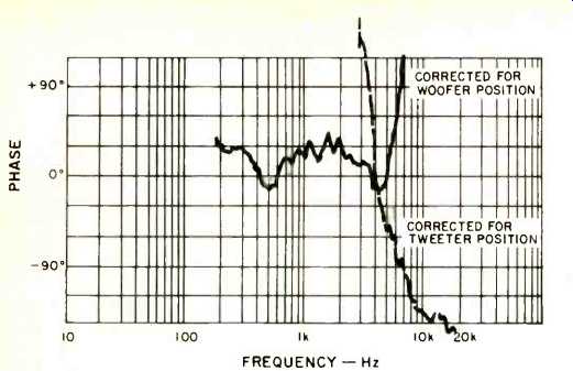
Fig. 4-One-meter axial phase response corrected for acoustic position of
woofer and tweeter.
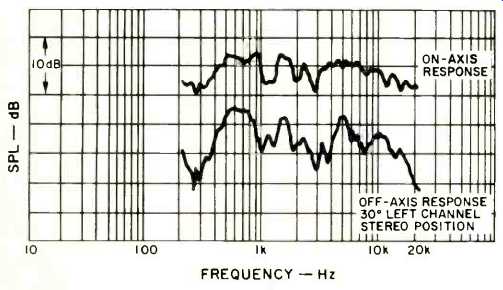
Fig. 5-Three-meter room response.
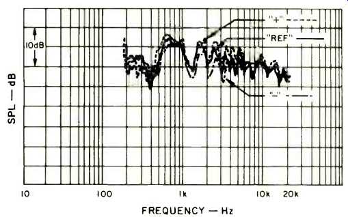
Fig. 6-Measured three-meter response in the actual stereo-left channel listening
position for each of the three KEF equalizer settings.
The magnitude of terminal impedance for each of the three equalizer settings is shown in Fig. 1. The lowest value of impedance occurs around 10 kHz and measures slightly over 6 ohms, while the highest value of impedance measures nearly 37 ohms and occurs around 1.3 kHz. While this impedance excursion is of little or no concern for the quality of sound from the KEF 104aB when driven from a low-impedance source, it does suggest that care should be taken in choosing speaker connecting wire so that the line drop will not influence tonal balance. Too small a speaker wire, such as 22 gauge, would cause a frequency response boost at 1.3 kHz relative to 10 kHz. For example, eight meters of 22 gauge cause a 1 dB response variation. Larger size wire should be used for the KEF 104aB.
The low-frequency resonance impedance rise at 54 Hz seems reasonable, while the amplitude measurement, which only extends down to 20 Hz, shows a minimum around 30 Hz with an indication of rising impedance at frequencies below 20 Hz. Figure 2 is the complex impedance plot of the KEF 104aB for the reference equalizer position and for a frequency range from 5 Hz to 20 kHz. The reason for the lower frequency impedance rise is now evident; there are two bass resonance impedance peaks, one at 15 Hz and the other at 54 Hz.
The 15-Hz resonance peak is the cause of an unfortunate difficulty in the listening test (which is always performed prior to laboratory measurements). This lower frequency resonance peak, associated with the passive radiator acoustic de sign of this system, lies in the region of resonance for many phonograph cartridge and arm combinations. Certain types of record warp can excite this resonance, with the result that the KEF woofer will literally drive itself wild on frequencies which it cannot reproduce. The result is an unacceptable distortion when the program content consists of strong low--frequency tones plus record warp. The bass response literally turns to pure mud with increasing playback sound levels. The problem is the interaction of program content, record warp, arm-cartridge combination, and KEF subsonic resonance. The solution which I used to eliminate this problem is discussed in the listening test.
Another potential impedance problem is associated with the substantial phase angle at around 3 kHz. With a phase angle nearly 60 degrees lagging, the KEF 104aB can place a reactive drive-angle demand on amplifiers which are driven near their peak power capability on strong upper register material, such as female vocal or brass. Only the better quality amplifiers should be used with this speaker to get the response it is capable of delivering at high sound levels.
The axial one-meter anechoic amplitude response is shown in Fig. 3 for a drive level corresponding to one average watt into 8 ohms resistance. The reference equalizer position is used for this measurement. Low frequency response extends down to about 60 Hz and then falls off at a slope of around 15 dB per octave below this frequency. The response is generally smooth through most of the range with a mild dip around 3 kHz and an overall fall-off of about 3 dB per decade with increasing frequency. The top end goes right on out to the 20-kHz limit of this test with no sign of cutoff, indicating a good, crisp response.
The measured anechoic phase response is shown in Fig. 4.
Since the signals from the woofer and tweeter do not arrive simultaneously at the one-meter microphone location, the phase measurement is shown for the corrected arrival time of these components. The woofer is essentially in phase with the electrical drive. This means that a positive-going voltage applied to the positive-marked speaker terminal produces a positive sound pressure at the listening location when the air-path time delay is taken into account. The tweeter has an opposing polarity; positive voltage produces a pressure decrease. The actual phase crossover occurs around 7 kHz.
The three-meter room response is shown in Fig. 5. In this measurement the speaker is placed against a back wall and raised 400 mm off a carpeted floor. The microphone is positioned in a conventional listening location, three meters in front of the speaker and one meter above the floor. Figure 5 is the frequency spectrum of the first 13 milliseconds of sound which arrives at the listener's location. The measurement shows two listening positions relative to the speaker, directly in front of the speaker (upper curve) and with the speaker in a left-channel stereo position (lower curve). The responses are separated by 10 dB for clarity of presentation.
With the exception of a response dip near 300 Hz, the KEF 104aB measures almost as well in this room response as it does under anechoic conditions.
In the earlier listening test I definitely preferred the equalizer on the KEF 104aB set to its "plus" position, rather than the "reference" position. I also preferred the KEF being rotated toward the listening position (as KEF recommends), for clarity of response and balance. In addition, I conducted my listening evaluation with experimental setups placing the KEFs in front of heavy drapes which could be opened to reveal an acoustically hard back wall or closed to give a moderate acoustic damping. I preferred the balance when the KEF's were placed 400 mm (15.75 in.) off the floor and against the acoustically absorbing back wall. Figure 6 is the response for the left-stereo channel speaker as measured directly where I sat during most of the listening tests. This even includes the effect of the chair in which I sat, but does not include myself as an acoustically intruding body. All three equalizer responses are shown in Fig. 6, and the comparison with Fig. 5 is interesting. The 300-Hz dip is gone when drapes are used as absorbing material, and the positive equalizer position definitely gives the best overall response. In most other respects, there is general agreement in these two three-meter room tests.
I concluded from these measurements and the listening test that the KEF 104aB has an excellent response for early sound if placed against an acoustically dead wall and rotated toward the listening area.
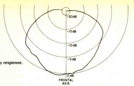
Fig. 7--Horizontal polar energy response.
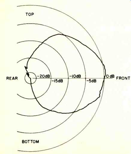
Fig. 8--Vertical polar energy response.
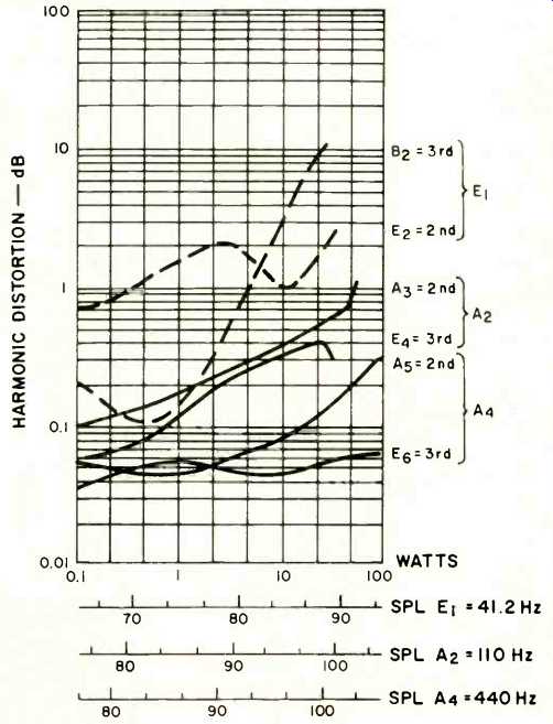
Fig. 9--Harmonic distortion for the tones E1 (41.2 Hz), A2(110 Hz), and A4(440
Hz).
The overall horizontal and vertical directivity patterns of the KEF are indicated in the polar energy responses of Figs. 7 and 8 respectively. All frequencies from 20 Hz to 20 kHz are uniformly weighted, and the net sound energy for this whole range is plotted as a function of listening position relative to the frontal axis of the speaker. Little can be said of the polar energy responses of this system other than that they are darn AXI good. There is enough energy radiated to the sides and up ward that this speaker should not be placed adjacent to objects which could scatter sound back into the listening area, such as lamps or overhanging shelves.
Harmonic distortion for the tones E1 (41.2 Hz), A2 (110 Hz), and A4 (440 Hz) is shown in Fig. 9. Low-frequency power handling, as with 41.2 Hz, is definitely a tough job for the KEF 104, as it cannot handle truly high-energy, low-frequency signals. However, 440 Hz is handled like a champ, with residual distortion well below that of many of the best speakers I have tested. In addition, 110 Hz is also quite good, with the KEF running out of steam at about 30 watts average with distortion products still below one percent. This system could use a subwoofer, cutting in below 100 Hz, to provide a balance of quality on the low end which is commensurate with its excellent mid- and top-end performance.
The intermodulation on 440 Hz caused by simultaneous excitation by 41.2 Hz is plotted in Fig. 10, and this intermodulation test is startlingly good. Up to 10 average watts, the intermodulation on 440 Hz is almost purely amplitude modulation, with phase modulation appearing above 30 average watts. The substantial difference between the IM and 41.2-Hz harmonic distortion implies that the passive radiator may be the culprit and that the active woofer is a very clean driver. In any case, the modulation of upper musical material by kickdrum and percussive bass is quite low. This implies that stereo imaging should not jump around with changes in low-frequency content.
The acoustic transfer gain of the KEF 104aB remains uniform at low average powers and begins to decrease above 10 average watts for pure tones of 262 Hz (middle C) and 110 Hz (A2). This implies that stereo lateralization of solo instruments should remain independent of sound intensity for all levels below about 96 dB SPL, but begin migrating toward center stage for higher sound levels. The timbre of solo instruments should also remain essentially independent of sound intensity up to this sound level.
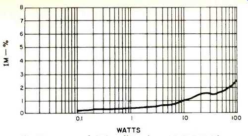
Fig. 10--Intermodulation distortion of A4 (440 Hz) by E,(41.2 Hz) mixed
one to one.
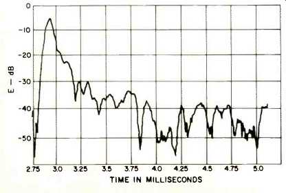
Fig. 11--One-meter axial energy-time response.
The crescendo test, where low-level single musical tones are checked for change in sound level when wide-band in coherent noise is suddenly superimposed, shows that the KEF hangs in there pretty well up to combined peak levels of around 105 dB. This implies that the stereo location of woodwinds, for example, will not jump kangaroo fashion when the brass lets go triple forte. This 105 dB, by the way, is the instantaneous peak, which can be readily achieved when listening to a clean direct-to-disc recording at brisk but not window-shattering levels. While the KEF is good, a high intensity studio monitor it is not.
The one-meter axial energy-time curve is shown in Fig. 11.
This is the envelope of the response of the speaker to a perfect band-limited impulse. The first sound at 2.84 milliseconds is due to the tweeter, with the woofer signal arriving at 3.15 milliseconds. The exponential die-off from 2.84 to around 3.25 milliseconds is due to the tweeter. After some small diffraction bumps, the residual tail of the impulse response stays more than 30 dB below the peak tweeter signal. This is quite a good transient response.
Listening Test
After considerable experimentation with placement of the speakers, I decided that the most realistic sound, to my ears, was obtained with the speakers placed against a heavily draped wall and angled toward the listening area. These speakers need to be raised off the floor to minimize bass dominance, and I chose to mount them on cloth-covered cinder blocks which elevated them 400 mm the positive equalizer setting on the KEF 104 for more natural realism of most program material.
The KEF 104aB does not have super-low-frequency response and could benefit from the services of a subwoofer.
At the beginning of the listening test I found a curious effect on certain organ and strong kickdrum recordings that I knew from experience were clean. As the sound level was raised on playback, a stage would be reached where the bass turned to pure mud. But this did not happen on all such records. When I removed the grille on the speakers I found that the offending records were causing the woofer and passive radiator to undergo violent low-frequency excursions. The problem was record pinch warps which created 10 to 15 Hz damped oscillations in the tonearm-cartridge combination and which in turn excited the loudspeaker excursions. I had not run into this problem before, even on vented loudspeaker systems, and it appeared to be associated with the 15-Hz resonance in the KEF. Switching in the rumble filter will eliminate this problem, but I do not like what most rumble filters do to low-frequency program content. I commented on this problem to our Kindly Editor at homebase, who sent me a DiscTraker for evaluation to see if it would help. The DiscTraker solved the problem completely and most impressively. This little gadget, made by Discwasher, Inc. of Columbia, Missouri, is a small dashpot which attaches to the cartridge and damps vertical cartridge motion. The results were startling, both to the visual motion of the woofer and the audible effect. I have several records with pretty bad warps which I use to test loudspeakers for susceptibility to warp.
One of these was totally unplayable at any level on the KEF 104aB without the damper and completely acceptable (except for pitch wobble) when the DiscTraker was installed.
The KEF 104aB is not a highly efficient loudspeaker and takes a moderate amount of amplifier power to reproduce sound at a brisk level. But what it lacks in efficiency, it makes up in clean KEF 104aB took the full peak capability of a Marantz 510 amplifier on drum snaps on the M&K Ed Graham Hot Sticks record (RT-106) without evidencing any audible strain. The only time I was able to run out of loudspeaker was on super-low bass from the famous E flat drum on Telarc's Fennell and the Cleveland Symphonic Winds version of Hoist's Suite No. 1(5038).
The KEF 104aB is one of the few loudspeakers which can reproduce a piano reasonably well. It still won't fool you into believing a real piano is being played in the room, but this speaker, in my opinion, does one of the best jobs around. It also does an excellent job in reproducing solo male and female vocals. Piano and vocals are, I believe, the very toughest items to reproduce.
Massed choral groups, for some reason, did not fare as well with this speaker. In fact, the female voices on a clean Beethoven 9th recording (M&K RT-112) sounded screechy to me.
I also found some difficulty with stereo depth on some pro gram material, although lateralization was usually excellent on all material.
The 104aB has good spectral balance from the lower mid range to the extreme top end. It is an accurate reproducer that intrudes very little on the sound. If you have a heavily draped or extremely large listening room, the KEF 104aB may not be able to provide the high intensity sound which some listeners like, but for most situations and listeners, I suspect that this system is quite adequate. The KEF 104aB is not a disco speaker and cannot provide heavy driving bass, nor would pipe organ aficionados fall in love with its performance.
However, and despite whatever negative comments I have made, the KEF 104aB is a speaker I can definitely recommend for accurate reproduction at moderate sound levels.
-Richard C. Heyser
(Also see: Audio magazine, Dec. 1979)
Also see:
KEF 105 Series II Loudspeaker (Feb. 1982)
KEF 107 Loudspeaker (Feb. 1988)
= = = =