Manufacturer's Specifications:
FM Tuner Section:
Usable Sensitivity: Mono. 10.3 dB: 50-dB
Quieting Sensitivity: Mono.
14.8 dBf: stereo, 38.3 dBf.
S/N Ratio: Mono. 82 dB; stereo. 73 dB.
THD (At 1 kHz): Mono. 0.08%; stereo, 0.1%.
Frequency Response: 30 Hz to 15 kHz, + 0 5, -0.8 dB.
Capture Ratio: 1.5 dB.
Alternate-Channel Selectivity: 75 dB
Image Rejection: 80 dB
I.f. Rejection: 100 dB.
Stereo Separation (At 1 kHz): 50 dB
AM Tuner Section
Sensitivity: 250 µVim: 30 external antenna.
S/N Ratio: 50 dB at 100 mV/m.
Selectivity: 38 dB.
Image Rejection: 40 dB.
I.f. Rejection: 5 dB.
THD (At 1 kHz): 0.5%.
Amplifier and Preamplifier Sections:
Power Output: 100 watts per channel, continuous. 8-ohm loads. 20 Hz to 20 kHz.
Rated THD: 0.007%.
Damping Factor: 45 at 8 ohms. 1 kHz.
Input Sensitivity: MM phono. 2.5 mV: MC phono. 250 µV: high level and tape. 240 mV.
Frequency Response: Phono, RIAA ±0.5 dB: high-level inputs, 5 Hz to 50 kHz. +0.-1.0 dB.
Graphic Equalizer Control Range: ± 10 dB at 63 Hz. 160 Hz. 400 Hz. 1 kHz. 2.5 kHz. 6.3 kHz and 16 kHz.
Loudness Control Action (At -30 dB Volume Control Setting): +6 dB at 100 Hz. +4 dB at 10 kHz.
S/N Ratio: MM phono, 80 dB: high level inputs. 77 dB.
General Specifications
Power Requirements: 120 V. 60 Hz, 350 watts (450 VA).
Dimensions: 17 1/8 in. (43.5 cm) W x 45/B in. (11.7 cm) H x 14-9/16 in. (37 cm) D.
Weight: 20 1/2 lbs. (9.3 kg).
Price: $650.00.
Company Address: 41 Slater Dr. Elmwood Park, N.J. 07407.
I can remember when a stereo receiver was a relatively simple piece of audio equipment: there was a simple tuner section with a slide-rule dial, a couple of tone-control knobs, volume and balance controls, a program selector switch, and a power amplifier section. How times have changed! JVC's new R-X500B receiver has the most elaborate looking front panel I have ever seen. The display section leaves nothing to your imagination: it tells you just about everything that's happening inside (and outside) the receiver. Normally, I would be critical of such a flashy video-graphics-like display, but this one truly clarifies and enhances the near-countless useful features this receiver sports. I'll try to enumerate all of the unusual features found in this. JVC .s top receiver for 1985, but if I miss any, it's only because there are so very many.
A microcomputer controls the digital quartz-synthesizer AM and FM tuner sections of the receiver. You can preset up to 15 AM and 15 FM stations for one-touch pushbutton recall. Using what JVC calls "Preset Scan." you can sample all of those preset stations, one at a time, for about 5 S each, to decide which one you'd like to "lock in." If the input signal during FM stereo reception is relatively weak, a "QSC" (Quieting Slope Control) circuit automatically reduces noise.
It’s actually a rather nice blend circuit, which reduces or cancels noise, while separation stays at still-acceptable levels. Instead of a conventional signal-strength meter or bank of LEDs, the R-X500B has a digital readout of actual signal strength, shown in dB above 1µV.
Instead of conventional tone controls, the JVC R-X500B features an electronically controlled, seven-band graphic equalizer (which they insist upon calling an "SEA"-for Sound Effects Amplifier). JVC and other receiver manufacturers have featured five- and seven-band equalizers in their products before, but this is the first receiver I know of that alters band setting electronically, at the touch of an 'Up" or "Down" button (no slider controls). It's certainly the first receiver to allow you to memorize and store five specific equalizer responses (plus their inverse curves) for instant recall. The selected response is shown in a special section of the elaborate display, and the same special display section works as a sort of real-time spectrum analyzer during normal use! A wireless remote-control unit (supplied) allows you to adjust such parameters as channel balance, volume, and program source selection. You can also call up preselected AM or FM stations remotely and even adjust the graphic equalizer or select any of is memorized response settings.
The display area, occupying nearly two-thirds of the up per half of the front panel, is divided into three major sections. At the left are the seven columns of indicators corresponding to the seven bands of the graphic equalizer. This display shows either the response curve set or selected or the spectral content (in each of its seven bands) of music being played through the receiver. Five tiny pushbuttons further to the left select any of the five memorized response curves. The middle display section tells you such things as program source selected (using symbols as well as words), volume-control setting, status of the tape monitor and dubbing switches, and whether or not the loudness circuit has been activated. The right-most display section is devoted to the tuner and. besides indicating tuned-to frequency, shows which station-preset button has been chosen, the condition of the received signal, and which tuning mode (manual or automatic) has been selected. The station-frequency indicator doubles as a digital indicator of actual signal strength (in dB) when an appropriate button is pushed. If the "OSC (blend) circuit comes on automatically because of weak stereo-signal reception, that is also indicated in this display area, as are a few other items relating to tuning mode and auto scan mode of the tuner section.
To the right of the display area are 15 numbered buttons plus a "Preset Scan" button, which is used to quickly audition the 15 preset stations. To the right of these keys are touch pads used to select program sources and tape monitoring and dubbing functions. Separate high-level inputs are provided for "AUX" and "DAD" (Digital Audio Disc or CD player) program sources. Two tape-monitor loops are avail able in this receiver.
About two-thirds of the way down the panel are several horizontally oriented, slim touch buttons. These are used to turn power on or off, to select either or both pairs of speakers, to switch the graphic-equalizer display from showing response curves to serving as a real-time spectrum analyzer, and to memorize graphic equalizer settings. Also present at this level are several buttons associated with the tuner section, such as a manual "Tuning" bar. a "Memory" button for storing preset frequencies, an "Auto Memory" switch which lets you scan usable signals and store them in memory at the same time, a switch labeled "CH/dB" which selects whether one of the displays will show station-preset numbers or incoming signal strength in dB, an FM mute button, and a button which selects the signal-strength level to which the auto-scan tuning will respond.
Along the lower edge of the panel, below the equalizer display area, are small pairs of touch buttons, each as signed to a specific equalizer frequency band. Touching the upper button boosts response at the designated center frequency, while pushing the lower button cuts response at that center frequency. A covered stereo headphone jack is located to the left of these equalizer adjustment buttons, while to their right are four additional controls associated with the graphic equalizer. The first of these is used to restore flat response. The next gives the inverse of the response curve (boost becomes cut. cut becomes boost), and the third and fourth select whether the equalized response should be applied to the program source or to the tape-recorder outputs.
The seven buttons remaining, at the bottom right, select MM or MC phono input, switch the loudness compensation on and off, adjust left/right balance, set volume, and switch the audio muting on and off.
The entire front panel is finished in black, while the displayed graphics and lettering range in color from yellow, through orange, to brown. JVC has another, lower-powered model (70 watts per channel), known as the R-X400, whose front panel is finished in silver and black. This model resembles the higher powered R-X500B in all respects except that it does not come with a remote-control unit, nor does it have a moving-coil (MC) phono input.
The rear panel is equipped with the usual array of input and output jacks. antenna terminals (for 75- and 300-ohm FM antenna lines as well as for an external AM antenna), twin sets of speaker output terminals, an AM and FM channel spacing switch (for the U.S.. 10 kHz on AM, 100 kHz on FM: for Europe and other areas, 9 kHz and 50 kHz, respectively), a pair of a.c. convenience outlets, a fuse-polder, a chassis ground terminal, and a DIN-type connector for one of the tape-monitor loops. A separate AM loop antenna is packed with the receiver and is installed at the rear panel so that it can be pivoted away from the chassis for best AM reception.
The amplifier section of the R-X500B utilizes JVC's Dynamic Super-A power amplifier circuitry. According to JVC, this circuit combines the positive attributes of both Class-A and Class-B circuitry. Because output transistors are never switched off, no switching distortion is generated. On the other hand, in terms of efficiency, the circuit behaves much like a conventional Class-B amplifier. Other circuit innovations built into this section are said to improve overall linearity and reduce open-loop (before application of feedback) distortion. Another new circuit, which JVC calls a Gm Driver (it has nothing to do with the Detroit Proving Grounds), is said to improve performance by driving the power stage at constant voltage, to reduce output impedance and achieve flat frequency response. This circuit is intended to negate the effects of counter EMF generated by the speaker load, while at the same time reducing distortion caused by the inherent nonlinearity of power transistors.
Tuner Measurements
Figure 1 shows signal-to-noise and distortion characteristics as a function of input signal strength for the receiver's FM tuner section. I measured excellent signal-to-noise ratios of 82 dB in mono and 78 dB in stereo for strong-signal inputs. Distortion in mono, for a 1-kHz modulating signal, decreased to a low value of 0.055%; in stereo, the same signal was reproduced with total harmonic distortion levels of only 0.09%. Fifty-dB quieting was reached with a signal strength of only 14.5 dBf in mono and 37 dBf in stereo. The stereo switching threshold (which corresponds to the muting threshold as well) measured 24 dBf. A plot of harmonic distortion versus audio modulating frequency is shown in Fig. 2 for mono and stereo reception. At 6 kHz, THD in stereo was still relatively low, at 0.15%.
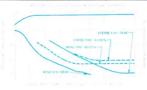
Fig. 1--Mono and stereo quieting and distortion characteristics, FM section.
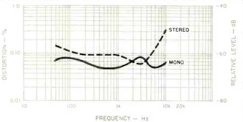
Fig. 2-THD vs. modulating frequency.
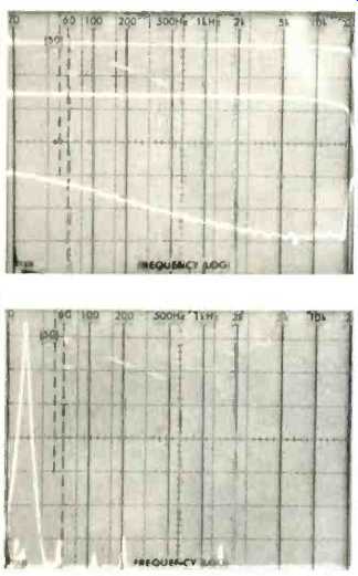
[top] Fig. 3 Frequency response (upper trace) and stereo separation with
OSC (middle trace) and without QSC (bottom trace). [above] Fig. 4 Crosstalk
and distortion products at the unmodulated channel's output, with a 5-kHz.
100°0 modulating signal applied to the opposite channel. Sweep is linear
from 0 Hz to 50 kHz.
Frequency response and channel separation for the FM tuner section are depicted in the 'scope photo of Fig. 3. The upper trace shows frequency response in stereo. Response was flat to within 0.5 dB all the way out to the highest broadcast frequency of 15 kHz. The lower curve represents crosstalk in the unmodulated channel's output. Separation was 55 dB at 1 kHz, decreasing to 40 dB at 100 Hz and 46 dB at 10 kHz. The middle curve in Fig. 3 shows what happens to separation when the OSC circuit operates (in the presence of weak signals). Essentially, separation is reduced to around 15 dB across the entire audio band, with attendant reduction in background noise.
Figure 4 illustrates the relative levels of crosstalk, separation and distortion components for a 5-kHz modulating signal applied to one channel. In this spectrum-analyzer 'scope photo, the sweep is linear from 0 Hz to 50 kHz. The two spikes at left are the desired 5-kHz signal (taller spike) and the undesired 5-kHz crosstalk showing up at the opposite channel's output. Other components in the output of the unmodulated channel, seen further to the right, are harmonics of 5 kHz and any 19- or 38-kHz subcarrier components that might be present. If you have been following my tuner and receiver reports over the last few years, you will recognize, as I did, that this tuner section is one of the best I have ever measured in terms of crosstalk and distortion products in the stereo mode. All of the unwanted components in the unmodulated channel's output are better than 65 dB below the level of the 5-KHz signal appearing in the modulated channel's output! Capture ratio measured exactly 1.5 dB, as claimed, while alternate-channel selectivity measured 75 dB. Image rejection was 82 dB, as against the 80 dB claimed by JVC, and i.f. rejection was in excess of the 100 dB claimed. AM rejection, not specified, measured a very high 65 dB.
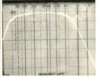
Fig. 5--Frequency response, AM tuner section.
Figure 5 is a plot of frequency response for the AM tuner section. Although audio fidelity of this section was not much better than that typically found in most receivers, usable sensitivity was very good, measuring a very low 10 µV as against 15 µV claimed. Signal-to-noise ratio in AM was also quite satisfactory, with readings in excess of 50 dB. Distortion, for a mid-frequency signal, was 0.4%, or slightly under the 0.5% specified by JVC.
Amp and Preamp Measurements
The power amplifier section of the R-X500B receiver delivered nearly 110 watts per channel into 8-ohm loads before there was evidence of clipping. At its rated output (100 watts per channel), THD for a 1-kHz signal was an almost unmeasurable 0.002%. In fact, to measure the THD for this amplifier I found it necessary to use my spectrum analyzer in a special setup (in combination with the "Distortion Output" of my distortion analyzer) which provides me with a useful dynamic reading range of more than 120 dB for any reference level. In this case, the reference level was 100 watts of output, and the THD components showed up some 95 dB below that reference. Figure 6 is a plot of harmonic distortion versus power output for frequencies of 1 kHz. 20 Hz and 20 kHz. At rated output. THD for a 20-kHz test signal measured only 0.0045%, while for a 20-Hz signal it was 0.005%.

Fig. 6--Power output vs. THD.
I measured a much higher damping factor for the receiver than was specified by JVC. My reading was an even 100, as against the claimed 45. The difference may well be caused by the fact that JVC specified damping factor for a 1-kHz signal, whereas the EIA Measurement Standard for amplifiers calls for the test to be made at a frequency of 50 Hz.
Dynamic headroom was a modest 0.83 dB. CCIF-IM distortion was extremely low, at 0.0039%, and IHF-IM distortion was below my limit of measurement, which is 0.03%.
Phono input sensitivity, referenced to 1-watt output, measured 0.25 mV for the moving-magnet (MM) inputs, 0.025 mV for the moving-coil (MC) inputs. A 24-mV signal at any high-level input produced an output of 1 watt with the volume control set to maximum. Phono overload measured 110 mV for the MM phono inputs and 20 mV for the MC inputs. RIAA equalization was slightly off at the low-frequency end, measuring +0.4 dB (relative to the ideal RIAA response characteristic) at 30 Hz. At the high end of the playback curve, the deviation was -0.5 dB at 15 kHz.
Overall frequency response via the high-level inputs was flat from 7 Hz to 45 kHz for the -1 dB roll-off point, and from 3.5 Hz to 90 kHz for the -3 dB cutoff limits.
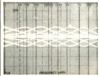
Fig. 7--Control characteristics of seven-band SEA equalizer.
The complete control range of the seven bands of the graphic equalizer is illustrated in the composite spectrum-analyzer ‘scope photo of Fig. 7. The perfect spacing of the filter's center frequencies is as accurate as any I have encountered during tests of separate, dedicated graphic equalizers.
Signal-to-noise ratio in phono, referred to a 5-mV input signal applied to the MM inputs and to a 1-watt output at the speaker terminals, measured a very outstanding 84 dB. For the MC inputs, using a referenced input signal of 0.5 mV, the S/N ratio was 69 dB. With the standard 0.5 V applied to the high-level inputs. SIN was 89 dB when referenced to 1-watt output. If you hooked up a CD player to this unit and then drove the R-X500B to within 3 dB of rated output during peaks in program material, the system would provide a total dynamic range of 106 dB -89 dB with respect to 1 watt, plus 17 dB to get to the 50-watt peak level (3 dB below rated output). That's more than enough dynamic range to handle any program on a Compact Disc or from any other digital audio source.
Use and Listening Tests
Admittedly, the JVC R-X500B is a receiver that takes a bit of getting used to-there are so many buttons to push and so many unusual features to learn about. Of course, the elaborate visual displays help greatly, and the more I played with this receiver and its many circuits, the more fascinated I became with what is now possible in a compact receiver. I can remember when the first microprocessor-controlled graphic equalizer with response storage memory was introduced as a separate component: It cost more than $2.000! And now here is that facility incorporated as just one of many features in an integrated receiver. The first frequency-synthesized tuner with preset facilities I ever tested was able to memorize no more than five favorite stations, as I recall, and it cost around $2.000. Now here is quartz-synthesized tuning with memories for 30 AM and FM stations in the tuner section of a $650 receiver.
I wish I had more time (and space) to detail all the other marvelous features of the R-X500B, such as its auto-scan and auto-tuning modes, its automatic switchover to stereo-blend for noise reduction, its ability to deliver five different user-made response curves and their inverse at the touch of a button, and its multi-purpose graphic spectrum-analyzer display and FM signal-strength indications. Suffice it to say that I had a ball playing with this receiver, and I suspect that anyone who buys it will have as much fun with it as I did. As for how it performed as a tuner and as an amplifier. I can only say that it was excellent. The tuner was sensitive enough and selective enough to enable me to pick up all my favorite strong and weak signals (over 50 of them) in FM. I did find one little annoying quirk in the QSC feature. When you tune to a weak FM stereo signal, the QSC circuit goes on, just as it's supposed to, and its light glows to indicate that noise has been reduced at the expense of separation.
But QSC does not shut off if the station's strength increases again, and there's no direct way to defeat it. The only way to disable the circuit and restore full separation is to tune away and then tune back.
Aside from that minor complaint I could find nothing to criticize about the R-X500B in terms of features, layout, or sound quality. The amplifier sounded great at loud listening levels. Perhaps even more important, during very soft passages (such as those likely to be encountered with program sources of wide dynamic range) sound was as clean as could be, with no residual noise or distortion to distract me.
I think perhaps many of us who come across a lot of new audio equipment tend to take some of the more recent design innovations for granted. We shouldn't! The JVC R-X500B is true state-of-the-art, if I may use that shopworn phrase once again. The engineering is superb in every sense. The uses to which the built-in microprocessor has been put are practical and not superfluous frosting on the cake. "Computerized" and "computer-controlled" are much overused terms these days in the audio industry. In this receiver, JVC can be forgiven for perhaps using these terms a bit loosely. The fact is that, whether you are controlling the R-X500B remotely from the comfort of your listening chair or via its front panel light-touch buttons, the unit responds as quickly and as surely as a computer, while providing sound that is not the least bit computerized or artificial-sounding. If I were confronted with just an FM/AM tuner that sold for the same price as this whole receiver and performed as well as the R-X500B's tuner section. I would have absolutely no hesitation in recommending it. If I found an integrated amplifier with a built-in. seven-band, electronically controlled graphic equalizer that performed as well as the preamplifier and amplifier section of the R-X500B and sold for the same price as this entire receiver. I would not hesitate to recommend it. That ought to give you some idea of my unqualified approval and recommendation of this true bargain receiver from JVC.
-Leonard Feldman
(Audio magazine, Dec. 1984)
Also see: Link |
JVC Model R-S77 Stereophonic FM/AM Receiver (Jan. 1981)
JVC R-X80 Receiver (Nov. 1983)
JVC RX-9V A/V Receiver (Mar. 1987)
JVC S-300 FM Stereo/AM Receiver (Sept. 1976)
= = = =