by Dr.-Ing. Klaus Genuit, and Wade R. Bray
Dr.-Ing. Klaus Genuit, the founder of Head Acoustics GmbH. in Aachen, West Germany, is the author of about 30 papers and holds seven patents the fields of dummy head transmission technique and telephone communications. Wade R. Bray is Director of Research and Development for Jaffe Acoustics (in Norwalk, Conn.), acoustical consultants and the North American distributor for the Aachen Head System. He designs sound systems (including electronic variable acoustic systems) for performance halls, consults on pipe organ and church acoustics, and also produces and engineers organ recordings.
The result of new research on human directional hearing, the Aachen Head System represents a substantial improvement in spatial imaging of complex sound fields via binaural recording. Developed in West Germany by Head Acoustics, we feel it is currently the most advanced noise analysis and recording device available. In this article we are going to discuss parts of the system, binaural reverberation and echo, compatibility with loudspeaker reproduction, production engineering, and applications.
The heart of the system is the Aachen Head, an artificial head that simulates our anatomy and physiology. It is constructed of rugged fiberglass. The Head and its associated signal processing electronics (Fig. 1) deliver a dynamic range in excess of human hearing (Fig. 2). To understand how a dummy head works, it is useful to know that human spatial hearing depends on a person's anatomy (Fig. 3). Because of reflections from shoulder to ears, the distance between the ears, the shadowing effect of the head on opposite-side sound waves, and resonances in the outer ear and the ear canal, sound from each direction has its own individual frequency response and arrival time difference. Taken as a whole, this characteristic is called the human outer ear transfer function (Fig. 4). This function can be mathematically modeled in order to design a dummy head that, along with the appropriate electronics and a headphone playback system, duplicates human hearing. Because it is possible to model the transfer function mathematically, it is also possible to feed monaural sounds into a computer, process them, and then play them back so that they are perceived as located at any desired position in space.
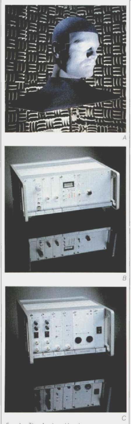
Fig. 1--The Aachen Head System consists of the Head itself (A), the Record
Processor (B), and the Reproduce Unit (C).
The principle of the acoustic measurement system used in the Aachen Head is shown in Fig. 5. A microphone 4 mm inside each ear-canal entrance simulates the human directional pattern of hearing, picking up direction modulated sound pressure, just as the human outer ear does. Recording sound signals at this point ensures that after they are processed and played back, your own unique ear canal/eardrum resonance system will re-create the original event. If recorded signals lack these characteristics, this analysis cannot be carried out by the human hearing process.
The transfer function and binaural ear/brain signal processing give human hearing its three-dimensional character. Since the direction-dependent filter effect of the outer ear is directly related to a person's anatomy, the shape of the transfer function varies from person to person (as suggested by the left part of Fig. 3). However, the shape of the Aachen Head's transfer function does not represent the individual properties of any particular test subject unless the Head system is programmed for that person's geometric-factor values.
The electrical circuit that describes the function and models human geometry is shown in Fig. 6. The elements of this model correspond to general acoustic parameters that have been assigned mean-factor values derived from the structural averaging of many test subjects. The model is divided into a direction-dependent part that simulates the directional filtering of the outer ear and a direction-independent part (chiefly consisting of various resonances) that, in combination with the first part, describes the free-field outer-ear transfer function. Using the output for free-field simulation, along with free field-equalized headphones, the ear signals of an "average test person" can be produced during playback for any direction of sound incidence.
Figure 7 shows the outer-ear transfer function of a test subject's left ear, calculated for two directions of sound incidence. The Figure also shows the minima and maxima of the function derived from six measurements taken from the same person. The measurements of outer-ear geometry have been simplified here for easy physical measurement, mathematical modeling, and calculation of the transfer function.
Although this simplification will yield errors, the errors are smaller than those caused by the limited accuracy of the transfer function of conventional recording technology.
The Outer-Ear Simulator
The outer-ear simulator (also known as an electronic artificial head, a sound-direction mixer, a binaural mixing console, or a "dummy" dummy head) is an electroacoustic device that transforms any input signal into two head-related ear signals. The characteristics of ear signals, which can be measured inside the ear canal, depend on the sound's frequency and on the direction of incidence.
A binaural mixing console filters any input signal, whether music recorded with conventional microphones or noise produced by vehicle simulators, in a way that corresponds to the filtering of the human outer ear. It is possible to model the outer-ear transfer function of any test subject for any direction of sound incidence and to simulate it through the use of a binaural mixing console.
A binaural mixing console offers other new possibilities (Fig. 8). This device allows a fully synthetic Head-type musical recording to be created without using a dummy head. In addition to microphone signals, input signals from any sound source that can be fed to a conventional mixing console may be combined on a binaural mixing console. Effects such as echo, reverb, doubling, and flanging may also be added. And engineers are no longer limited by the usual panpots, since the direction of sound incidence can be rotated 360° around the median and horizontal planes. Because the console produces ear signals which are flat for frontal free-field incidence, recordings made this way are more transparent than those produced by stereo mixing-even when reproduced on loudspeakers.
Experiments have shown that in normal rooms, the time delay is not critical between the output signals of the Aachen Head and those of the binaural mixing console. Even if no time-delay compensation is applied, spaciousness and transparency are not really influenced. If the room has a long reverberation time, and the signal of an auxiliary microphone is strongly amplified, artificial reverberation may be added to prevent the sound source from seeming unrealistically near.
If the room has a very short reverb time, such that the energy associated with the diffuse sound field is negligible compared to the direct sound, then time-delay correction assumes greater importance. Correction ensures that a recording made using auxiliary microphones will sound natural and will not lose the high-quality transfer characteristics of the Aachen Head.
Associated Electronics
The Aachen Head System uses free field equalization for loudspeaker or headphone playback. Equalization is divided into two parts, one part handled by the Record Processor, the other by the Reproduce Unit.
The Record Processor is an intermediate unit that outputs to the recording medium or analysis equipment. Connected to the Aachen Head, the Record Processor contains the free-field equalizers that remove the outer-ear transfer function for direct sound in front of the Head, so that these sounds will have flat response, while those from other directions will still be affected by the differential between the transfer functions for frontal and other sounds. For sounds within the frontal hemisphere, these frequency effects will not be radical enough to be perceived by the ear/brain system as sound colorations. Instead, these differences provide clues to the ear/brain about height, depth, and spread beyond the left and right speakers.
The Reproduce Unit contains free field equalizers that replicate variations of air pressure at the entrance to the ear canal. These do not perform the inverse of the Record Processor's equalization but rather compensate for the transfer function of the headphones used and for the effects of the headphone's presence on the ear's resonances. Thus, the original sound event is reproduced for each headphone listener.
The effectiveness of this can be demonstrated by switching back and forth between the same event as heard through loudspeakers fed from the Record Processor's output and through headphones fed from the Reproduce Unit. The loudspeaker sound is degraded only by crosstalk from the speakers, which can be cancelled by the use of such processors as the Lexicon CP-1 and the Transaural Processor by Duane H. Cooper and Jerald L. Bauck.
Stax SR-Lambda Professional headphones are used with the Aachen Head System for critical measurement work because of their stable transfer functions with repeated wearings and their relatively uniform response to variations in outer-ear shapes. These were derived from the original StaxLambda headphones. For research inside moving cars, Mercedes-Benz required more energy at lower frequencies, and the Stax SR-Lambda Professional headphones were developed specifically for that purpose. Of course, other headphones may be used, provided they are free-field equalized, either by their mechanical design or by the use of an appropriate reproduce equalizer.
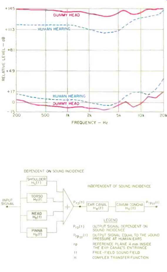
Fig. 2--The dynamic range of human hearing is less than that of the Aachen
Head System.
Fig. 3--The human external ear transfer function. The cavum concha is the antechamber to the ear canal.
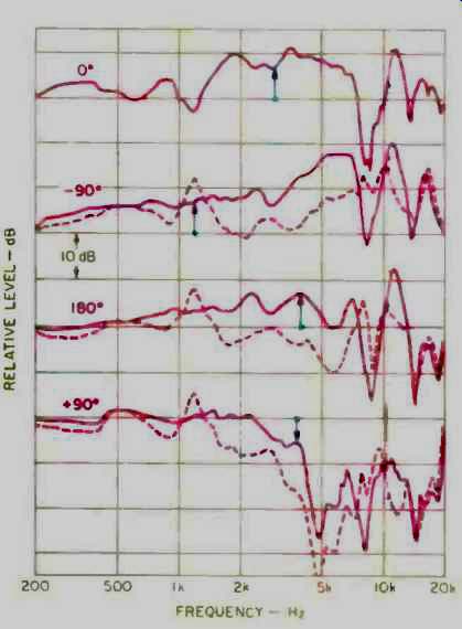
Fig. 4--Transfer function of the left ear, measured 4 mm inside the entrance
of the ear canal, for four angles of incidence (straight ahead, to the left,
straight behind, and to the right). The base of each arrow indicates reference
SPL. Solid curves represent the free-field (direct-sound) external-ear transfer
function, while the dashed curves represent the difference, at each direction,
relative to frontal free-field sound incidence.
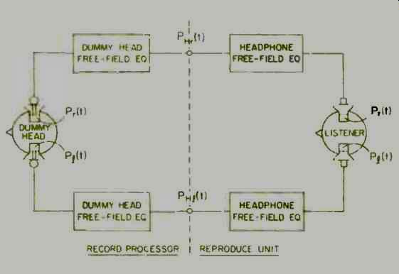
Fig. 5--Block diagram of the Aachen Head System. The two dummy head free-field
equalizers in the Record Processor are adjusted to produce the inverse of
the frontal free-field transfer function of the Aachen Head, thereby producing
flat response at the intermediate point (dashed line). This flat signal is
then recorded and can be used for loudspeaker playback and for measurement.
The headphone free-field equalizers in the Reproduce Unit yield a linear
free-field transfer function of the headphone, so the sound pressures presented
at the entrance of the listener's ear canals will duplicate those at the
entrance of the Head's ear canals.
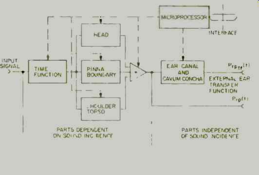
Fig. 6--Principle of the external-ear simulator (one channel shown). Note
that the transfer function is subdivided into direction dependent and direction
independent parts. The time function models the arrival time differences
for different azimuth (horizontal) angles; this time difference is zero for
sound sources directly in front of the listener and is at its maximum for
90° left or right sound incidence.
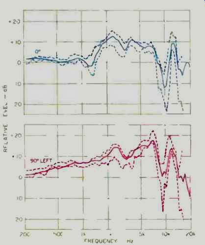
Fig. 7--Outer-ear free-field transfer functions of a test subject's left
ear, for sounds arriving from the front (top curves) and directly to the
left (bottom curves). Solid curves show the calculated functions, dashed
curves show the measured minima and maxima derived from six measurements
of the test subject.
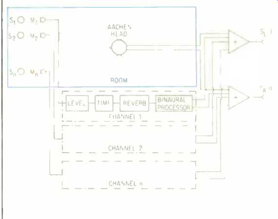
Fig. 8--The binaural mixing console, showing how monaural microphone signals
are processed to derive a pair of binaural ear signals (which allow placement
of the original signals anywhere in the spherical sound field), and the
mixing of these signals with signals from the Aachen Head.
Reverberation and Echo
In principle, binaural reverberation can be created by convolving (the processing of one transfer function by the characteristics of another) the impulse response of a room with a recording that was produced either by the Aachen Head or by a binaural mixing console.
When recording using the Aachen Head, the two output signals (left and right ear) can be described as a convolution of the sound source with the impulse response of the room and the outer-ear impulse response of the Head for every direction of sound incidence. Such a convolution is carried out by our own outer-ear transfer function when we listen to any sound. The output signals may also be viewed as a convolution of two separately recorded signals, the binaural impulse response of the room and the binaural sound source in an anechoic chamber.
The length of a room's impulse response may vary from milliseconds to seconds. This implies a convolution of the input signal with an impulse response of 100 to 50,000 calculated points, at a cutoff frequency of 10 kHz, something impossible to realize in real-time signal processing. Digital reverberation units found in nearly all studios can simulate the transfer characteristics of various room-reverberation models.
Until now, however, there were no binaural reverberation units. Such units are required when dealing with binaural technology, because the signals of monophonic reverberation units cannot be added to the original binaural signals, as is done with traditional multi-microphone techniques. Since the reverberation signal must also be directional, tests have been performed to answer the following questions: How many reflections have to be filtered by the outer-ear transfer function in order to replicate the original sound event in a real room? Which direction of sound incidence should be chosen for each of the reflections? Which reverberation units are suitable to simulate a natural Head-related reflection pattern? What filtering of the reverberation signal is necessary to provide a good analogy with the transfer function of real rooms? Is it necessary to add reverberation to additional microphones used during the production of an Aachen Head recording?
Our tests led to the arrangement shown in Fig. 9. First, we recorded a speech signal in different rooms, using the Aachen Head. Then, we simulated the recorded sound event, using the same speech signal without any natural reverberation, binaural processing, or digital reverberation units.
Listening tests showed that a minimum of three early reflections should be filtered by outer-ear transfer functions. The directions of the simulated sound incidence were frontal in the median plane, and to the right and left of the listener at varying angles. When simulating a large room with a long reverberation time, the sound incidence of the lateral reflections should be within an angle of 90° to 120° (Fig. 10). When simulating long, narrow rooms, the first lateral reflections should have an incidence of 45° to 90°. Generally, an engineer must correct the color of the reverberation signals.
Typical room resonances are not usually simulated by reverberation units, but by equalizers. An equalizer should also be used to compensate for the additive effect of both ear signals, which occurs in listening to binaural reverberation. At lower frequencies, this effect leads to an exponential addition of the ear signals, because they are in phase. At higher frequencies (above 1 kHz), the addition of the signals becomes stochastic (random), with a loss of 3 dB.
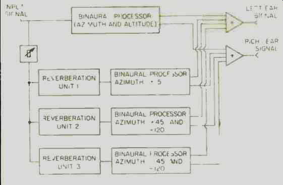
Fig. 9--Use of the binaural mixing console to synthesize different rooms
for binaural listening. Reverberation and reflections are appropriately directionalized
and mixed to closely simulate naturally occurring sound fields as heard in
real rooms. Each ear signal contains outer-ear transfer functions for that
ear.
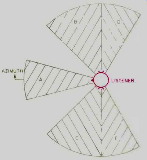
Fig. 10--Angles of incidence of direct sound (segment A) and reflections
directionalized to simulate real rooms. In a small hall, reflections are
primarily from direction segments 8 and C. while for large halls they are
primarily from direction segments D and E. Psychoacoustic research has shown
that it is not necessary to have reflections and reverberance from all directions
in order to create a highly convincing reconstruction of hall acoustics.
Compatibility with Speaker Reproduction
At the time the Aachen Head System was developed, research and many experiments with loudspeaker reproduction led to the choice of free-field equalization rather than diffuse-field equalization.
Since the Record Processor contains the free-field equalizers which remove the outer-ear transfer function for sound sources in front of the Head, this means that for a frontal source (direct sound) the function is a constant and becomes identical to the constant of standard measurement microphones. This makes the output fully compatible with other acoustic instrumentation, and it provides excellent loudspeaker playback.
For source incidences other than frontal, loudspeaker-playback imaging is improved by the differential contribution of the outer-ear transfer function, as has been previously noted.
When recording with Aachen Head technology, both headphones and loudspeakers should be used to verify all recordings. This is necessary because some characteristics of binaural processing are not active when played back on loudspeakers. For example, an effect called "binaural reverberance suppression" leads to a different balance between direct signals and reverberation, depending on whether one listens on headphones or loudspeakers. When listening to an Aachen Head recording on headphones, the human ear is able to suppress reverb, so that more reverb might be recorded than would be optimal for good loudspeaker reproduction.
In addition, sound engineers should listen to loudspeaker playback to check for undesirable changes in tone color, an effect that sometimes occurs at large angles of incidence when sound sources are filtered by the outer-ear transfer function. If this happens, the direction of the sound source, which equals a modified transfer function, should be varied until loudspeaker reproduction is satisfactory. Or the problem could be solved by filtering the signal.
If adjusted for these effects, Aachen Head recording technology is fully compatible with stereophonic recording for playback on loudspeakers.
Most of the time, in fact, better results are obtained than if conventional stereo miking and mixing techniques are used. At the same time, a natural, realistic reproduction of the original sound event is always obtained when listening on headphones.
Production Engineering
Aachen Head recordings are usually intended to reproduce an original sound event as naturally as possible, so that editing won't be necessary. If consecutive recordings are made, as in a studio, for example, then in order to get the correct acoustic balance, such recordings should be made in the same room without changing the position of the Head. In contrast to conventional multi-track recording, the Aachen Head needs only two tracks, one for the left and one for the right ear signal. When recording in a studio having short reverberation time, the position of the Head may be changed, because the influence of the room's transfer function is negligible. The reverberation signal of a room can also be simulated by the use of reverb units, as we have described.
In performing initial experiments in splicing different Aachen Head recordings, the results were very satisfying.
Recordings produced by this technique have been judged quite good, especially when rated for transparency, naturalness, and spaciousness.
We have often mixed the signals of auxiliary microphones with the output signals of the Aachen Head. If the microphones are positioned at a distance from the Head, their signals should be compensated for the time delay and then processed by applying to each the appropriate directional transfer function.
When filtering Aachen Head signals, some effects must be taken into consideration. If parametric or graphic equalizers are used, only small changes should be made, and the filtered frequency ranges should not be amplified too highly. Sound engineers who use equalizers need to remember that sound imaging by human listeners is based on signal processing that analyzes not only interaural time differences but also interaural and monaural frequency response. The special frequency characteristics of the human outer-ear transfer function lead to a differential contribution in sound imaging, especially in the median plane, where no interaural time differences can be detected.
The use of shelving equalizers normally will not change the structural form of the outer-ear transfer function.
Filtering of frequencies below 500 Hz will also have no effect, as the influence of the function is negligible in this range.
Head Acoustics binaural analysis system with keyboard and mouse (center), flanked by Reproduce Unit for electrostatic headphones (left) and specially modified DAT recorder (right).
System Applications
Since 1981, German automotive firms have used the Aachen Head to analyze interior and exterior noise. As part of the process, listening juries assemble for playback of noise samples and judge the subjective annoyance of noises associated with each design. Their work has helped produce quieter automobiles.
Engineers began using Aachen Head technology for such evaluation when they realized that a measurable and objective determination of annoyance was only rarely achieved by conventional means. Previously, they had attempted analysis using techniques such as A-weighted sound-pressure levels or 1/3-octave spectra. However, they were unable to verify by measurement the clearly perceptible effects of various noise-abatement procedures; in fact, some noises subjectively rated as very annoying showed a lower A weighted sound pressure level than less annoying noises.
What is the reason for such disparity? The difference lies in the complex, dynamic way the human ear and brain process sound events. We appreciate not only the sound level of a signal but the distribution of amplitudes, spectral composition (simultaneous masking), and temporal structure (pre- and post-masking). Our outer ear is a complex acoustic filter and, in marked contrast to the spherical characteristics of a conventional microphone, is strongly direction-oriented.
Since outer-ear transfer functions affect how the ear and brain process signals and recognize patterns, different masking effects, and thus different sound and noise impressions, are obtained using Aachen Head technology instead of conventional microphone recordings. The Head also enables the listener to use his ability to pluck single sounds from a noisy background and to suppress others by ear/brain signal processing.
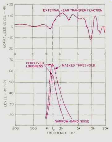
Fig. 11--At frequencies which are amplified by the ear's transfer function,
tones can be discerned in the presence of noise that, to a microphone,
would mask them. Here, a 2-kHz pure tone, discernible to ear or microphone
at the lower of two noise levels, is discernible only to the ear when the
noise level is raised. See text.
This ability is due to the differences between the sound-masking properties of human spatial hearing and those of normal microphones with linear transfer functions. In Fig. 11, for example, the top curve is the external ear transfer function for sound sources in front of the listener. In the presence of a narrow-band noise centered at 1.5 kHz, with a perceived loudness of about 60 dB, an additional pure 2-kHz tone with a level of 35 dB can be heard by both the ear and the microphone. If the narrow-band noise is increased to 70 dB, the microphone no longer "hears" the pure tone-it will be masked. However, the external-ear transfer function amplifies this frequency by 10 dB; thus, for a listener, the tone is not masked. Such effects occur at various frequencies for various angles of incidence, so measurement and perception of noise often correlate poorly unless the nature of human hearing is taken into consideration.
An important attribute of the Aachen Head in applications is the ability to calibrate the playback level for precise correspondence with the original record level, using headphones. This makes it easy to recognize the significant signal or spectral parameter and to decide how to manipulate the components of the sound source. Such evaluation often shows that the high-energy spectral components are not always responsible for acoustic discomfort. Even greater irritation may result from lowering the components, because their masking effects are simultaneously reduced.
Figure 12 shows the amplitude spectra of interior noises caused by automobile tires at a speed of 100 kilometers/hour. The measurements were taken on a roller test stand inside an anechoic chamber using the Aachen Head System. Two different types of tires that were rated to be equal with respect to the A-weighted sound pressure level were tested. However, the tire corresponding to the dashed spectrum in the Figure was judged to cause a much more annoying noise.
What accounted for this? The spectral domain contained certain tonal components that underwent a frequency modulation (harshness) in operation. When trying to reduce the noise effects of the tires corresponding to the solid spectrum in Fig. 12, one might assume that the frequencies between 1.1 and 1.4 kHz were responsible and therefore try to attenuate this range.
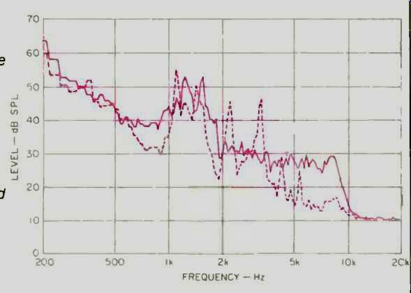
Fig. 12--Spectrum plots for two tires whose overall A-weighted sound levels were
identical when the tires were run at 66 mph on a roller in an anechoic room.
The tire with the solid spectral curve was rated as not annoying, while the
tire shown by the dashed curve was rated as very annoying. The perceived annoyance
was caused by rapid frequency modulation of spectral components at 4.8 and
6.3 kHz, due to tread-block design. Slight reduction of the output at these
frequencies solved the annoyance problem without changing the dBA of the tire.
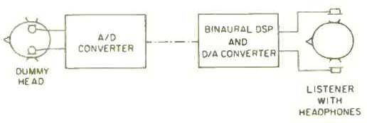
Fig. 13--Basic block diagram of the binaural analysis system (BAS). Dummy head
signals, free field equalized for frontal incidence, are digitized and then
manipulated by the digital signal processing computer. This allows editing
in the time domain and detailed study of the frequency domain while the signal
is heard binaurally (recreation of the original hearing event). Annoying
noise factors can then be found and analyzed, even in transient events.
However, when variously filtered Aachen Head recordings were compared in subjective tests, it was clearly demonstrated that damping these frequencies would not improve acoustic corn fort inside the automobile. The final results proved very interesting: By lowering the spectral components at 4.8 and 6.3 kHz, a significant improvement in acoustic comfort was achieved.
In addition to automotive applications, the Aachen Head System is suitable for fields in which measurement and evaluation of acoustic signals are connected to comfort and quality. For example, the system can be used for long-term archiving and documentation, training of service personnel, optimization of loudspeaker sound systems, quality control, evaluation of acoustical comfort, and other cost and time-effective testing.
An important field of application has been noise analysis using a computer controlled binaural analysis system (BAS), aspects of which are shown in Figs. 13 and 14. The BAS can calculate sound pressure level (unweighted or with A, B, or C weighting), loudness (in sones), and sharpness (the ratio of high-frequency energy to average energy); it can also perform 1/3-octave analysis and calculate and display transfer functions and binaural tracking filter characteristics. Moreover, the system can calculate cross- and auto-correlation functions, measure short time spectra to evaluate dynamic effects, measure and show interaural levels and phase relationships, and calibrate playback levels for precise correspondence with the original sound pressure levels at the ear-canal entrances. Long time functions can be recorded and processed, and segments selected for repeated playback.
Sound quality can be analyzed with respect to amplitude and frequency modulation, tone color, and other qualities. Dynamic range can be calculated with respect to pre-masking, post masking, and simultaneous masking effects. And the system can replicate both ear signals in the original time and frequency domains.
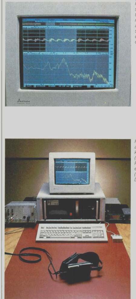
Fig. 14-This BAS display shows an edited recording that isolates an annoying
noise, and the noise's associated frequency spectrum. The system's computer
also performs many other functions; see text.
Summary
Engineers have become increasingly convinced that conventional acoustic measurement techniques do not adequately meet their needs in noise measurement and analysis, room acoustics, and recordings. The use of the Aachen Head System yields considerable improvement in results. This has been shown by tests and by numerous applications in the automotive and recording industries. All have shown that by using what we know about the signal processing capabilities of human hearing, we can obtain a virtually objective analysis of Aachen Head signals with regard to sound properties.
Binaural measurement techniques allow for much clearer classification of sound quality, particularly with respect to judgments about the annoyance level of noise. Applying Aachen Head technology will save time and money, because the decision-making processes will tend to be more goal-oriented and faster.
Beyond offering a new dimension of noise measurement and analysis, Aachen Head technology enhances sound reproduction. If an "acoustic photograph" of a concert is desired, for example, we believe only Aachen Head technology is able to faithfully reproduce the original event in every detail, from clarity and timbre to dynamics and spatial imaging.
Engineers now have a recording tool that handles acoustically difficult sites and replicates a sound event by more adequately representing the spatial imaging of complex sound fields. The Aachen Head System also provides outstanding results when used as a microphone array for loudspeaker reproduction. Both binaural and stereo playback capabilities inhere in the same recording.
References
Cooper, Duane H. and Jerald L. Bauck, "Prospects for Transaural Recording," Journal of the Audio Engineering Society, January/February 1989 (Vol. 37., No. 1/2).
Genuit, K., "A Special Calibratable Artificial-Head Measurement System for Subjective and Objective Classification of Noise," proceedings of the Internoise Convention, July 1987 ( Cambridge, Mass.), pp. 1313 to 1318.
Genuit. K., "Investigation and Simulation of Vehicle Noise Using the Binaural Measurement Technique," Noise and Vibration Conference 1987, April 1987 ( Traverse City, Mich.), pp. 97 to 104.
Gierlich, H. W. and K. Genuit, "Processing Artificial-Head Recordings," JAES, January/February 1989.
Griesinger, David, "Equalization and Spatial Equalization of Dummy-Head Recordings for Loudspeaker Reproduction," JAES, January/February 1989.
(Source: Audio magazine, Dec. 1989)
Also see:
Binaural Overview: Ears Where the Mikes Are--part 1 (Nov. 1989)
A History of Binaural Sound (Mar. 1986)
Link | --Illusions for Stereo Headphones (Mar. 1987)
The Filter in out Ears (Sept. 1986)
= = = =