AMAZON multi-meters discounts AMAZON oscilloscope discounts
 .
.
If you do any of these projects, you can alter the construction methods, but try to make the internal cubic volume of the box equal to that of the plans. Refer to earlier projects for details of any particular construction method and to Section 3 for guidelines on desirable box qualities.
PROJECT 10: TWO-WAY IN A PINE BOX
Here is a low-cost 2-way system that offers smooth sound (Fig. 10-1). Pine boards are adequate for small enclosures, but here the pine is lined with W particle board for extra strength and rigidity (Fig. 10-2 and Table 10-1). Build the pine shell first, then glue in the liner. The liner should be recessed 1 1/8" from the front edges and 3A" from the back edges of the box walls. The speaker board and back panel can be glued and nailed directly to the liner, no cleats needed. The internal dimensions should be about 9.78" x 17 1/2" x 7.30".
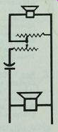
The 16 uF capacitor that comes with the mid-range tweeter can be used as a high-pass filter (Fig. 10-3). An 8-ohm L-pad to compensate for varying acoustical conditions completes the project.
PROJECT 11: EXTENSION SPEAKER
This extension speaker can be built without power tools. By painting the box flat black and using a storage crate to cover and protect it, minor flaws in your cabinet work will not be noticeable (Fig. 10-4).
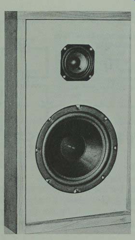
Fig. 10-1. Pine box and 2-way system combine to give smooth low cost sound.
For a local volume control on a stereo pair of these speakers, you can install a double L-pad in a standard wall box of the room where the speakers are installed (Table 10-2). Or you can install a single L-pad in the back of each speaker (Fig. 10-7).
For easy wall mounting, get a set of metal wall brackets and ...
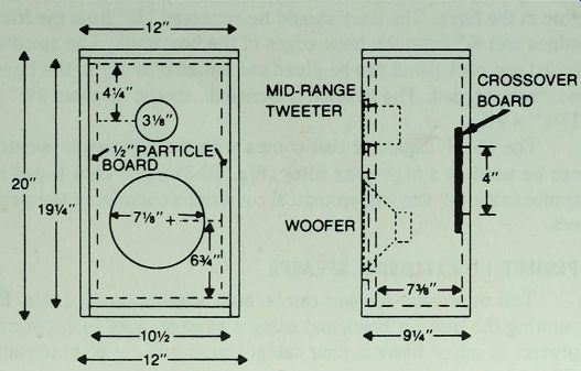
Fig. 10-2. Enclosure plans for Project 10.
-------------
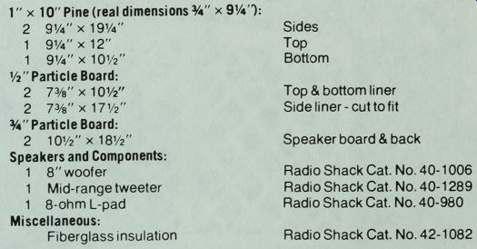
Table 10-1. Parts List for Project 10.
1" x 10" Pine (real dimensions 0.75 " x 9 1/4"):
2 9 1/4"x 19 1/4" Sides
1 9.25" x 12" Top
1 9 1/4"x10.5" Bottom
1/2" Particle Board:
2 7 3/8"x10.5" Top & bottom liner
2 7 3/8"x17 1/2" Side liner -cut to fit
0.75" Particle Board:
2 10 1/2"X 18 1/2" Speaker board & back
Speakers and Components:
1 8" woofer, Radio Shack Cat. No. 40-1006
1 Mid-range/tweeter, Radio Shack Cat. No. 40-1289
1 8-ohm L-pad, Radio Shack Cat. No. 40-980
Miscellaneous:
Fiberglass insulation, Radio Shack Cat. No. 42-1082
-------------------
... install one in the upper back of each speaker (Fig. 10-6). If you prefer a more conventional looking extension speaker, use the enclosure plans for Project 10 for the 8" full-range speaker.
PROJECT 12: LARGE WOOFER TWO-WAY SPEAKER
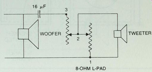
Fig. 10-3. Wiring diagram for Projects 10 and 12.
The introduction of a new Radio Shack mid-range tweeter that can be used down to 700 Hz makes this 2-way system practical.
The 10" woofer offers deeper bass than is possible in most 2-way systems (Fig. 10-8).
Note that the wiring circuit for this project is identical with that of Project 10, each one using the 16 uF high-filter capacitor supplied with the mid-range tweeter (Fig. 10-3).
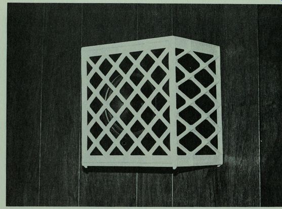
Fig. 10-4. Storage crate protects and enhances appearance of extension speaker.
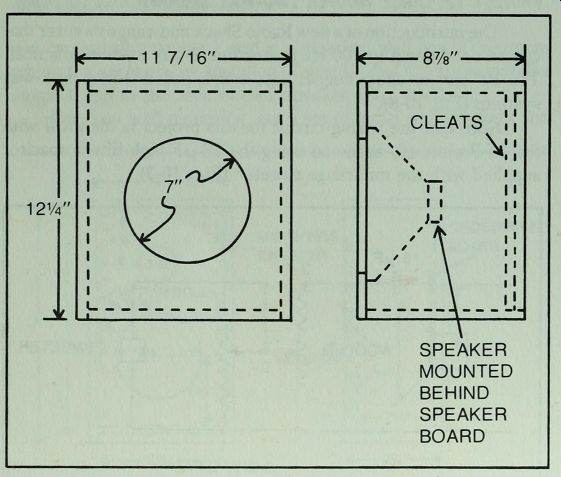
Fig. 10-5. Enclosure plans for Project 11. If a more conventional box is desired,
build one to the plans for Project 10.
SPEAKER MOUNTED BEHIND SPEAKER BOARD
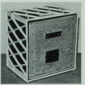
Fig. 10-6. Metal bracket in upper back makes wall installation easy.
The enclosure shown was built from birch plywood (Fig. 10-8 and Table 10-3). The walls were assembled with beveled corner joints, and cleats were installed to hold the speaker board and back panel. The enclosure for Project 2 has the same internal volume and can be used if you change the speaker cut-outs (Fig. 10-9).
PROJECT 13: A PORTED SYSTEM WITH SPECIAL DAMPING
In testing a 6V2" woofer, Radio Shack Model No. 40-1009, I found different values from the parameters published in the catalog. My tests showed:
= 57.5 Hz
= 0.6
= 0.7 cu. ft.
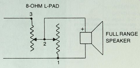
Fig. 10-7. Wiring diagram for Project 11. L-pad may be installed in speaker
box or, if stereo control is used, in wall switch box.
-----------
Table 10-2. Parts List for Project 1 1.
0.75" Plywood
1 11 7/16" x 12 1/4" Speaker board
2 8 3/8" X 12 1/4" Sides
2 8.5" x 10.5" Top & Bottom
1 10.25" x 11 Vs" Back Crate:
1 13 1/4" x 12 1/4" x 9 1/2" Sterilite No. 1590
Speaker and Components:
1 8" Full range speaker Radio Shack Cat. No. 40-1286
1 Terminal plate Radio Shack Cat. No. 274-625
1 Stereo volume control Radio Shack Cat. No. 40-978
Or use 1 L-pad in each enclosure
Miscellaneous:
Fiberglass insulation Radio Shack Cat. No 42-1082
Metal Wall bracket Radio Shack Cat. No. 40-150
------------
The optimum volume ported box turned out to be 2.4 cu. ft., rather large for a 6.5" woofer. However with a 1" layer of fiber glass stapled tightly over the back of the woofer (Fig. 10-12), the Q can be lowered to 0.5. This reduces the optimum volume to 1.43 cu. ft. Because this woofer is small for a box of such volume, less ...
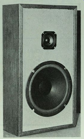
Fig. 10-8. Large 10" woofer gives this speaker deeper bass than is possible
with most 2-way systems.
------------------
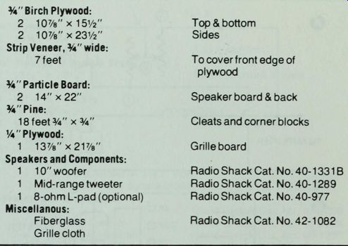
Table 10-3. Parts List for Project 12.
0.75" Birch Plywood:
2 10 7/8"x15 1/2" Top & bottom
2 10 7/8 "x23.5" Sides Strip Veneer, .75 "wide. 7 feet
To cover front edge of plywood
0.75 " Particle Board:
2 14"x22" Speaker board Aback
0.75 " Pine:
18 feet 0.45 " x 0.45 " Cleats and corner blocks
0.25" Plywood:
1 13 7/8"X 21 7/8" Grille board
Speakers and Components:
1 10" woofer Radio Shack Cat. No. 40-133 1B
1 Mid-range tweeter Radio Shack Cat. No. 40-1289
1 8-ohm L-pad (optional) Radio Shack Cat. No. 40-977
Miscellaneous:
Fiberglass Radio Shack Cat. No. 42-1082 Grille cloth
----------------
Note: If desired, the enclosure for Project 2 may be used.
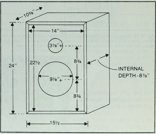
Fig. 10-9. Enclosure dimensions for Project 12. Use cleats to hold speaker
board and back. Internal volume is identical to that of box for Project 2.
Project 2 box can be used for Project 12 with only the speaker board cut-outs
changed.
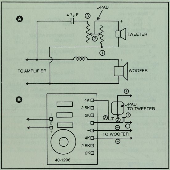
Fig. 10-10. Wiring circuit for Project 13. A is the schematic diagram of the
4000 Hz crossover, and B shows how to wire 2-way crossover network, Radio Shack
Model No. 40-1296. Don't use the capacitor mounted on the tweeter.
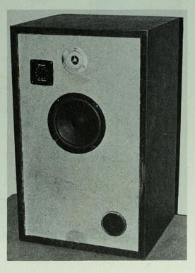
Fig. 10-11. Project 13, complete except for grille cloth.
-----------------------
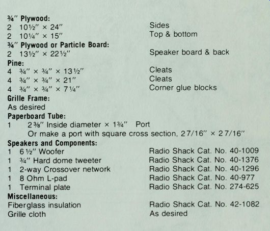
Table 10-4. Parts List for Project 13.
0.75" Plywood:
2 10.5" x 24" Sides 2 10.25" x 15" Top & bottom
0.75" Plywood or Particle Board:
2 13.5" x 22.5" Speaker board & back
Pine:
4 3/4" x W x 13 1/2" Cleats
4 3/4" x 3/4" x 21" Cleats
4 3/4" x 3/4" x 7 1/4" Corner glue blocks
Grille Frame: As desired
Paperboard Tube:
1 2 3/8" Inside diameter x 1 3/4" Port
Or make a port with square cross section, 2 7/16" x 2 7/16"
Speakers and Components:
1 6 1/2" Woofer Radio Shack Cat. No. 40-1009
1 3/4" Hard dome tweeter Radio Shack Cat. No 40-1376
1 2-way Crossover network Radio Shack Cat. No. 40-1296
1 8 Ohm L-pad, Radio Shack Cat. No. 40-977
1 Terminal plate, Radio Shack Cat. No. 274-625
Miscellaneous:
Fiberglass insulation Radio Shack Cat. No. 42-1082
Grille cloth, As desired
--------------------------
... than 10% overvolume was planned, making a box of 1.5 cu. ft. a practical choice (Fig. 10-11).
In wiring this, don't use the capacitor supplied with the tweeter.
You'll find this system, with the special damping, gives a controlled natural sounding bass response. If you like a more dominant bass, you can try it without the damping pad on the woofer.
PROJECT 14: CAR SPEAKER
Use 0.25 " tempered hardboard for this little box (Fig. 10-14). If you have power tools, dado the side edges of the top and bottom and all around the speaker board, as shown in the plans (Fig. 10-15). If you have no power tools, use butt joints.
Glue the box walls and speaker board together. Use the hardware that comes with the molded speaker grille (Table 10-5) to install the grille and the 4" speaker. If you don't plan to use the grille, you can install the 4" speaker from outside the box, but it will be unprotected. No crossover network is required (Fig. 10-16).
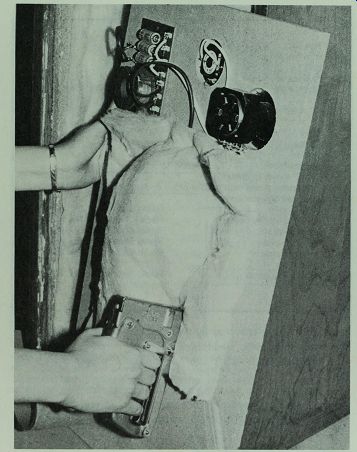
Fig. 10-12. Staple a 12" x 12" sheet of 1" fiberglass over
the woofer. Fiberglass pad should be pulled taut.
Secure the speaker to the shelf under the back car window by locating bolts in the box to match the locations of speaker mounting bolts in the car body. If you can find bolts that are long enough, you can run the mounting bolts from the speaker board through the box and shelf. For this kind of installation the shelf serves as the back of the enclosure. Fill the space under the box with loose damping material. If you can't find long bolts, use shorter bolts through the back and glue the back to the box.
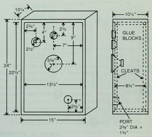
Fig. 10-13. Enclosure plans for Project 13.
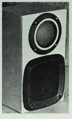
Fig. 10-14. Molded grille over the full range speaker and built-in dome on
the tweeter give protection to the drivers in this car speaker.
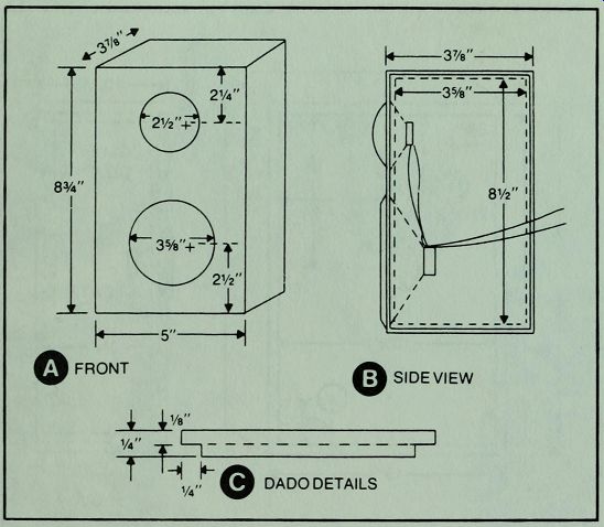
Fig. 10-15. Enclosure plans for Project 14. Dado is used on each side edge
of top and bottom, on all edges of front and back panels.
PROJECT 15: UTILITY MUSICAL INSTRUMENT SPEAKER
This project is for those musicians who like the sound of an open-backed speaker. It gives a more pronounced middle bass response, but the user should be aware that the power input to the speaker must be limited somewhat more than if it were totally enclosed. This disadvantage isn't as serious as it sounds; the open back enclosure gives a middle bass resonance that makes the system more efficient than it would be with a solid back.
Table 10-5. Parts List for Project 14.
-------------
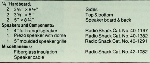
0.725”Hardboard:
2 3 5/8"x8 1/2" Sides
2 3 3/8" x 5" Top & bottom
2 5" x 8 1/4" Speaker board & back
Speakers and Components:
1 4" full-range speaker Radio Shack Cat. No. 40-1 197
1 Piezo speaker with dome Radio Shack Cat. No. 40-1382
1 5" moulded speaker grille Radio Shack Cat. No. 40-1291
Miscellaneous:
Fiberglass insulation Radio Shack Cat. No. 42-1082
Speaker cable
--------------------------------

Fig. 10-16. Wiring diagram for Project 14.
Cut out the parts and assemble the shell with glue and nails (Fig. 10-17 and Table 10-6). Install cleats, recessed 1 1/4" from the front edges, %" from the rear edges of the walls. Glue and nail down the speaker board and the rear short panel. Cover the box with cloth-backed vinyl, following the instructions for Project 8.
Install metal corners, then the speakers (Fig. 10-18). Make up a grille board and cover it with grille cloth. Install it with ornamental screws.
If desired, you can install a carrying handle on each side.
PROJECT 16: PA SPEAKER
This column speaker (Fig. 10-19) gives excellent voice reproduction, but its bass response is more limited than that of most stereo or musical instrument speakers. The vertical column provides good horizontal sound distribution with good freedom from feedback (Fig. 10-20).
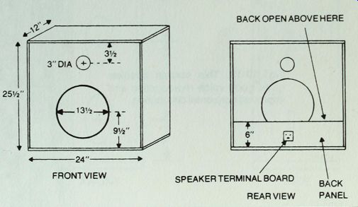
Fig. 10-17. Enclosure plans for Project 15. Cover enclosure with cloth-backed
vinyl and use metal corners, as was done in Project 8 •
-----------------
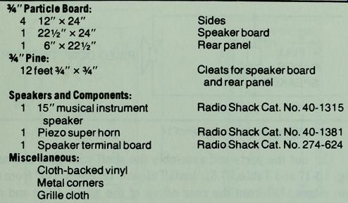
Table 10-6. Parts List for Project 15.
0.75" Particle Board:
4 12"x 24" Sides 1 22.5" x 24" Speaker board
1 6" x 22.5" Rear panel
0.75" Pine:
12 feet 0.75"x 0.75" Cleats for speaker board and rear panel
Speakers and Components:
1 15" musical instrument speaker
1 Piezo super horn Radio Shack Cat. No. 40-13
1 5 Radio Shack Cat. No. 40-138
1 1 Speaker terminal board Radio Shack Cat. No. 274-624
Miscellaneous:
Cloth-backed vinyl
Metal corners
Grille cloth
----------------------
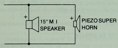
Fig. 10-18. Wiring diagram for Project 15.
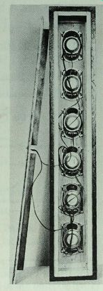
Fig. 10-19. This column speaker gives good voice reproduction and improved
horizontal distribution.
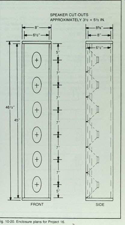
Fig. 10-20. Enclosure plans for Project 16.
If you install the speakers behind the speaker board, round off the front edges of the cut-outs. Loosely fill the enclosure with cut pieces of damping material.
For a 12-ohm impedance, wire the speakers in 3 paralleled pairs, then wire the 3 pairs in series. Or, for an impedance of about 5 ohms, put 2 groups of 3 speakers in parallel, then wire the 2 groups in series (Fig. 10-21).
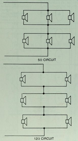
Fig. 10-21. Choose the wiring circuit to match the impedance you need for
Project 16.
With the speakers specified (Table 10-7), the rated power handling capacity is 180 watts. For small rooms you can shorten the column and use four speakers. Wire them in two paralleled pairs, the pairs in series for a standard 8-ohm impedance.
----------------
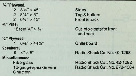
Table 10-7. Parts List for Project 16.
0.75" Plywood:
2 8 3/8 x45" Sides
2 8 3/8"x8" Top & bottom
2 6 1/2"x45" Front & back
0.75” Pine:
18 feet 0.75" x 0.75" Cut into cleats for front and back
0.75" Plywood:
1 6 "x 44 7/8" Grille board
Speakers:
6 4"x6" Radio Shack Cat No. 40-1298
Miscellaneous:
Fiberglass Radio Shack Cat. No. 42-1082
16-gauge speaker wire Radio Shack Cat. No. 278-1384
Grill cloth
-----------------------
Next: