In this final SECTION, results of performance measurements on the power supply projects from SECTIONs 4 and 6 are listed, along with troubleshooting tips and a calibration procedure for the switching power supplies.
TYPES OF MEASUREMENTS
The measurements made on the linear supplies were load regulation, power output, percent regulation, and rms ripple voltage. The measurements made on the switching power supplies included input regulation, conversion efficiency, ripple voltage, control voltage, t,y, and the sample and reference volt ages under various loads. The results are provided in a series of tables. The percent of load regulation is calculated using the equation given in SECTION 4.
LINEAR POWER SUPPLIES
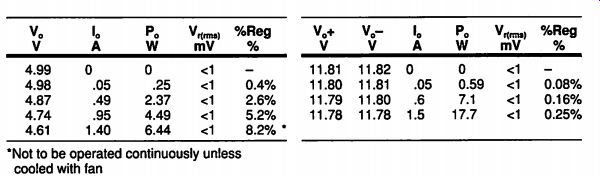
Table 7-1. +5V Series-Pass Power- Supply Measurements; Table 7-2. +12V Series-Pass
Power-Supply Measurements. *Not to be operated continuously unless cooled with
fan.
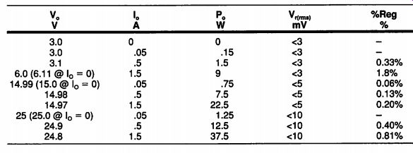
Table 7-3. Adjustable
Power-Supply Measurements
SWITCHING POWER SUPPLIES
The switching power supplies in SECTION 6 used readily available parts, but some of the parts are capable of greater precision than others, therefore, adjustments are provided to overcome these variations. First, a potentiometer allows the reference voltage applied to the non-inverting input (pin 5) of the 723 IC to be varied. Second, a switch allows the control loop to be opened, and with a voltage from another potentiometer, to directly vary the PWM output pulse width. These adjustments, used with the calibration procedure that follows, allow the switching power supplies to be precisely adjusted to the correct output voltage, regardless of component variations.
Switching Power Supply Calibration Steps
1. Disconnect the power supply providing V_in.
2. Place S1 in the Calibrate (open-loop) position, toward the open-loop potentiometer (R17 for the +5V supply, R16 for the +24V supply). This connects the wiper tap of the potentiometer to the PWM control-voltage input.
3. Set the potentiometer to the middle of its adjustment range.
4. Connect a load resistor across the output of the supply that will draw approximately 500mA (10 ohm for +5V, 50 ohm for +24V).
5. Connect a voltmeter across the power supply output to monitor Vj,
6. Turn on the power supply for Vy.
7. Adjust the open-loop potentiometer to obtain the desired V,- +5V for the step-down converter, +24V for the step-up converter.
CAUTION: Turning the open-loop potentiometer should produce a smooth, even change in V _ If the V, change is erratic, replace the 556 and repeat the procedure. Some 556s double trigger, causing erratic operation.
8. With V_o set to the correct level, measure the voltage at pin 4 of the 723, and record it.
9. Measure the voltage at pin 5 of the 723, and adjust the reference-voltage adjustment potentiometer until the voltage at pin 5 equals the voltage at pin4.If, on the step-up converter, the potentiometer does not have enough adjustment range to bring the pin-5 voltage down to the level at pin 4, replace R2 with a wire (shorts R2) and repeat this step.
10. Measure the control-voltage output of the 723 at pin 10. It should be within the 3V-10V linear range of the 723. If the voltages on pins 4 and 5 differ by more than 0.1V, the 723 output will be either 3V or 10V, depending on whether pin 4 or pin 5 is greater. For the supply to operate properly, the voltages at pins 4 and 5 must be the same. If they are, and the pin-10 voltage is outside the linear range, replace the 723 and repeat the procedure.
11. Turn off V_IN and place S1 in the Normal (closed loop) position which connects pin 10 of the 723 to pin 11 of the 556.
12. The supply is now calibrated and should regulate V_o to the desired voltage when V_in is turned on. Slightly trimming the reference-voltage adjustment potentiometer may result in greater V, accuracy.
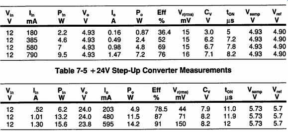
Table 7-4; Table 7-5 +24V Step-Up Converter Measurements
TROUBLESHOOTING TIPS-INITIAL OPERATION
There are five major reasons that a power supply circuit doesn't operate initially:
1. Wrong Circuit Connection--Check the circuit carefully to make sure all connections are correct. The switching power supply circuits are somewhat detailed, and thus, more difficult to build.
2. Bad Connections--It is easy to have a cold solder joint so that a connection is open; reheat the suspected joints. Or solder may have run between connections to produce a short; especially on ICs. Use an ohmmeter or continuity meter to check for shorts.
3.Wrong Component Values--Assure that all component values are correct. A common cause is that the color coding on resistors was read incorrectly.
4. Bad Components-Integrated circuits, transistors and diodes are very sensitive to heat, static electricity, and conditions that exceed specifications.
They may have been damaged when soldered if heated too long, or because a built-up static charge discharged through it. Or due to wrong circuit connections, voltage, current or power specifications may have been exceeded. Remember, the linear regulator ICs will shut down if they are asked to supply excessive current or get too hot. A short in the circuit could cause this condition and make it appear that the regulator is bad. Look at the problem and analyze it carefully.
5. Circuit Oscillations--When a circuit oscillates, a signal is being fedback from output to input to provide positive feedback to cause the resultant output to get larger rather than negative feedback to keep the output under control.
The cause is that there is too much gain in the circuit or the feedback signal time relationship (phase) is wrong. Clean circuit layout and short leads are very important to keep circuits from oscillating. A 0.1uF capacitor to ground or to the power rail is a good tool to try to stabilize oscillations. Connect it to the various circuit points by trial and error. If the circuit stabilizes, see if a layout change or amplifier gain reduction might solve the problem.
The feedback loop may have to be opened so that the circuit can be adjusted to proper operating conditions before the loop can be closed. Use the switching power supply calibration procedure as an example of how this is done.
It is suggested that voltage measurements be made around the power supply circuit once it is operating to use for troubleshooting if the power supply were to fail.
TROUBLESHOOTING TIPS-OPERATIONAL FAILURE
After a power supply has been operating properly and then fails, here are some common causes: :
1. Fuses--A fuse has blown. Replace the fuse.
2. Exceeding Specifications--Sometime during the use of the power supply, the specifications were exceeded. If a short is placed on the switching power supplies of SECTION 6, the switching current of the diodes will be exceeded, and the diodes will be damaged. In this case, the diodes usually short rather than open. If the supplies are allowed to operate without a load, high voltage will destroy the diodes and all the ICs. In this case, the diodes usually open.
The only solution is to replace components.
3. A Connection Has Opened or Shorted--Make voltage and continuity or resistance measurements to isolate the problem. Repair the faulty connection. Here is where a chart of voltages around the circuit, taken when the circuit is operating properly, is very helpful.
4. A Component Has Failed--Resistors may change in value, capacitors and transformers usually short, switches and contacts become corroded. ICs and other semiconductors open because of excessive temperature cycling, short because of excessive voltage or current, or burst open because of excessive heat.
VOLTAGE, CURRENT AND RESISTANCE MEASUREMENTS
Remember, when making voltage measurements, measure across a component, or an input or output. When measuring current, turn off the power, break into the circuit, and put the multitester in series with the circuit component.
When measuring a component's resistance, turn off the power and disconnect one end of the component from the circuit. Leaving the component in the circuit may damage the meter or may cause errors in readings. For anyone needing help with multitester measurements, Radio Shack has a guide titled Using Your Meter, RS #62-2039, that shows how to apply a multitester.
SUMMARY
In this guide, basic concepts and fundamentals are presented, including design guidelines, component selection and why, and actual practical designs de tailed so they can be built. The objective was to promote understanding and have success by applying it. We hope we have met our goal.
Prev: Link | --SECTION 6 SWITCHING POWER SUPPLY PROJECTS
Building Power Supplies (Article Index)
Also see:
Link |