by RICHARD J. KAUFMAN
In stereo, both ears hear both speakers, and stereo imaging suffers. Restoring image solidity and moving the image out into the room just takes an extra pair of speakers and one potentiometer.
One of the more interesting stereo add-on devices is the image enhancer. The first of these devices, such as Bob Carver's Sonic Holography and Sound Concepts' Im age Restoration System, were electronic. Passive devices relying on extra speakers are also possible, and such speaker systems have been introduced, most notably by Polk Audio.
It is relatively simple to add passive image enhancement to your stereo system; the only additional components required are a potentiometer and an extra pair of speakers. This effect is well worth experimenting with; at its best, it can give an uncanny solidity to reproduced music by moving the apparent sound source out from between the speakers and into the room.
The premise on which image enhancement is based is that because both speakers are heard by each ear, degradation of stereo separation and imaging is inevitable. Listen to your system. Even with your eyes closed, it is always possible to tell where the speakers are. Similarly, your system cannot produce a sound whose apparent source is further left than the left speaker, nor further right than the right.
The reason for this is illustrated in Fig. 1A. The signal from the left speaker is also heard by the right ear, delayed and attenuated by a factor of alpha due to the longer path length involved. Electronic image enhancers create a version of the left-channel signal, with the same delay and attenuation as that created by the longer path length, then invert it and mix it into the right channel. When this signal from the right speaker reaches the right ear, it cancels out the undesired signal from the left speaker. The same process is applied to the other channel.
(You may be wondering what happens to the inverted cancellation signal when it arrives at the opposite ear. Since it is doubly attenuated, it is no longer significant in determining localization.)
The same thing can be done if the delayed and attenuated signal is re produced by a separate speaker, as shown in Fig. 1B. When this process is successfully carried out, each ear only hears the signal from one channel much as is the case with headphones, except that the sound stage doesn't appear to be inside one's head. Instruments can seem to come from the far right or far left, depending on the signal's political preference, or they may even be at your elbow. There are some disadvantages: The ideal listening position is more circumscribed than normal, and the effect is not suited to every recording.
Ideally, you will want four identical speakers to set up your own image enhancer, but this is not strictly necessary. Imaging may suffer unless the speakers are very well matched in terms of frequency response, but the general ambience will come across even if the imaging is less precise. It is suggested that you experiment with in expensive speakers before duplicating your main speakers.
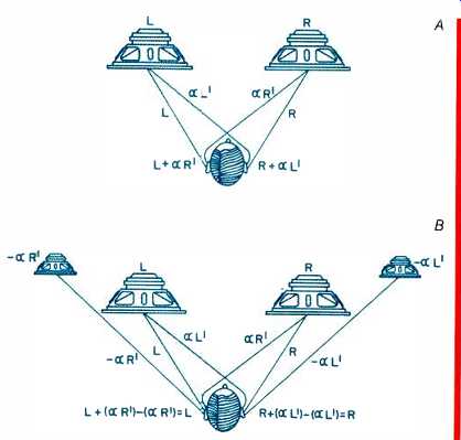
Fig. 1--With normal stereo (A), each ear picks up a delayed, attenuated
version of the signal meant for the other ear. This degrades separation and
imaging. By feeding to each ear signals that cancel the interaural crosstalk
(B), imaging and separation are restored.
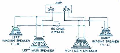
Fig. 2--Wiring diagram of a passive image-recovery system using two extra
speakers to produce an inverted, crossfed difference signal. Attenuation
is controlled by the rheostat-wired potentiometer shown, and time delay is
controlled by the position of the imaging speakers.
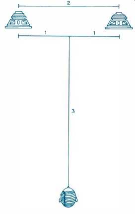
Fig. 3--For optimum image recovery, the listener should be positioned on
the center line between the speakers, 1 1/2 times as far from the speakers
as they are from each other.
The electrical hookup is shown in Fig. 2. Scale of you may recognize this as being similar to the Dynaco quad system from the early '70s. Like that system, we are using only the difference (L- R) signal. This part of the signal carries all of the directional information, so it is sufficient to use it alone.
There is an added advantage in that bass is primarily non-directional and mono, so it will not be reproduced this way, relieving your amp of an unnecessary load.
The potentiometer should be rated for at least 2 watts. Any resistance value between 25 and 100 ohms is okay.
Unfortunately, such pots are not easy to find these days, and some scrounging may be necessary. ETCO some times carries such pots, but they are not always available. (Alpert-Mansell Associates, Dept. A, 1650 Broadway, Suite 608, New York, N.Y. 10019, has agreed to supply a suitable pot for $7.50, plus sales tax in New York. Allow six to eight weeks for delivery.) A cautionary note: The extra load imposed by the additional speakers may overload some amplifiers. Generally, there will be no problem if the amp is rated at 60 watts or more, and many amps rated at lower power also deliver enough current to avoid difficulty. If the manufacturer does not recommend driving extra speakers in parallel, you may have problems. In such a case, if the image speakers are more efficient than the main speakers, the proper setting of the potentiometer will assure a high enough load not to bother the amp. In any case, a 2-A speaker fuse at the amp's output, which is usually provided by the manufacturer, should protect the amp. If you have any doubts whether this circuit is suitable, write to the amp's manufacturer.
To position the imaging speakers, you will want to keep their path length to the listener about 6 inches longer than that of the main speakers. Most bookshelf speakers, with drivers no larger than 8 inches, can be placed next to each other to achieve this.
Larger systems will require you to move the imaging speakers forward slightly. Also, the ideal listening position will be different than for normal stereo: The effect works best when the speakers are slightly closer together than is usually the case. The optimum distance to the listener should be chosen according to the distance between speakers, following approximately the ratio shown in Fig. 3. You will want to adjust the pot so the signal from the imaging speakers is 3 to 6 dB down compared to that from the main speakers, or about half as loud. If you follow these rough guidelines, only a little experimentation will be necessary to get the best results.
This may remind readers of a similar system I wrote about in the May 1983 Audio. The main technical difference is the use of L- R and R- L imaging signals here, while the previous system used -R and - L. In practical terms, the system shown here is a bit simpler to build and much more likely to give good results without elaborate tweaking and the use of test instruments.
The older system was theoretically capable of slightly better results, but only if the speaker impedances were relatively constant and if the capacitor values were precisely right for the impedance of the particular speakers used.
As capacitors in that size are rarely precise, and speaker impedances vary, the older system required a great deal of tweaking.
(Source: Audio magazine, Nov. 1986)
Also see:
Link | --Illusions for Stereo Headphones (Mar. 1987)
Headphones around the house (May 1974)
Headphones: History and Measurement (May 1978)
A History of Binaural Sound (Mar. 1986)
The Filter in out Ears (Sept. 1986)
Link | --Build A LIVE END/DEAD END Listening Room--PART I
= = = =